Note: Descriptions are shown in the official language in which they were submitted.
CA 02809955 2013-03-19
INTERMEDIATE COMPOSITE PANEL
FOR ROOFING AND WALLS
FIELD OF THE APPLICATION
[0001] The present application relates to multi-layer
construction or building panels and, more particularly, to a
intermediate composite panel such as roofing or wall panel and
methods of manufacturing and assembling same.
BACKGROUND ART
[0002] In the construction industry, multilayer panels are
frequently used, as such panels offer multiple functions
related to the layers that compose them. Such multilayer
panels can benefit from their various layers (e.g.,
elastomeric, asphalt, fiberboard, EPS or XPS, fiberglass,
mineral wool etc.) to offer features such as structural
support, waterproofness, insulation and fire-resistance.
[0003] In fabricating multilayer panels in factory, in
plant, there results faster installation at the construction
site, and therefore a reduction on the labor required.
Moreover, the quality of assembly of the multilayer panel is
controlled in plant, while the assembly of multiple layers on
the construction site may result in some errors and incorrect
assembly.
SUMMARY OF INVENTION
[0004] It is an aim of the present invention to provide a
novel construction panel for walls and/or roofing providing
additional features.
[0005] The panel is a composite product that is made in
factory so as to have controlled quality.
[0006] Therefore, in accordance with the present
application, there is provided a composite intermediate panel
comprising: a structural layer providing the structural
-1-
CA 02809955 2013-03-19
integrity of the composite intermediate panel; pressure-
sensitive adhesive layers on opposite main surfaces of the
structural panel, the pressure-sensitive adhesive layers
applied in plant; a backing sheet layer for each adhesive
layer, the backing sheet layer adhered to the pressure-
sensitive adhesive layer, and being peelable off the pressure-
sensitive adhesive layer to expose the pressure-sensitive
layer; and at least one attachment unit of rigid material on
at least one of the main surfaces of the building panel, the
at least one attachment unit being positioned at a location
where mechanical fasteners secure the building panel to a
structure.
BRIEF DESCRIPTION OF THE DRAWINGS
[0007] Fig. 1 is a side view, fragmented, of an
intermediate composite panel constructed in accordance with an
embodiment of the present disclosure;
[0008] Fig. 2 is a side view, fragmented, of an
intermediate composite panel similar to that of Fig. 1, with
an additional functional layer;
[0009] Fig. 3 is a side view, fragmented, of an
intermediate composite panel similar to that of Fig. 1, with
rabbet edges;
[0010] Fig. 4 is a side view of a bottom layer of the
intermediate composite panel of Fig. 1, as mounted to a
structure, with a top layer of composite panel thereon; and
[0011] Fig. 5 is a top plan view of the intermediate
composite panel of Figs. 1 and 2.
DESCRIPTION OF THE PREFERRED EMBODIMENTS
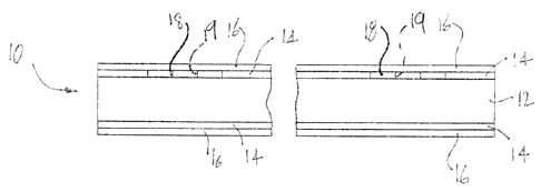
[0012] Referring now to the drawings, and more particularly
to Figs. 1 and 5, an intermediate composite insulated building
panel constructed in accordance with an embodiment is
- 2 -
CA 02809955 2013-03-19
generally shown at 10, and is also referred to as multilayer
building panel.
[0013] In the embodiment of Fig. 1, the insulated building
panel 10 has five layers, namely a structural layer 12,
adhesive layers 14, and backing sheet
layers 16.
Additionally, attachment units 18 are provided on one of the
surfaces of the building panel 10.
[0014] The structural layer 12 provides structural
integrity to the building panel 10. More specifically, the
structural layer 12 may be a relatively rigid panel made of a
polymeric material, such as urethane-based polymers (e.g.,
polyisocyanurate) or polystyrene, among possibilities.
Such
material have some structural properties in addition to
insulation properties. Moreover, an additive is optionally
used to add a flame and/or smoke retardant property to the
structural layer 12. In another embodiment, all six faces of
the structural layer 12 are coated with asphalt.
As an
alternative to the materials suggested above, it is considered
to have layer 12 made of a perlite panel, rock wool, wood
fibers, expanded or extruded polystyrene, polyurethane,
polyisocyanurate, cement, gypsum or other materials. Coatings
may be used to treat the structural layer 12 before the
application of the adhesive layer 14, to ensure optimal
adherence of the adhesive. The material(s) used for the
structural layer 12 are dependent on the contemplated use.
For instance, the structural layer 12 may be used for sound
insulation, thermal insulation, or the like.
[0015] The thickness of the structural layer 12 is selected
as a function of the contemplated use of the building panel 10
(e.g., flat roof, pitch roof, wall, ceiling, etc.).
For
instance, a suitable thickness for the structural layer 12
ranges between 0.25" to 8.0" (with the thicker range including
a functional layer, as described hereinafter).
- 3 -
CA 02809955 2013-03-19
[0016] The adhesive layers 14 respectively cover at least a
portion of the two main surfaces of the structural layer 12,
if not a substantial portion, or a complete coverage of the
main surfaces. It is pointed out that all six surfaces of the
structural layer 12 may be covered with adhesive layers 14.
The adhesive for the layer 14 is a pressure-sensitive, auto
adhesive applied in plant, whereby the adhesive must maintain
adhering properties at ambient temperatures. As an example,
the adhesive used for the layer 14 may be at least one of a
bitumen adhesive, polyurethane resin, urethane and
polyurethane-based adhesive, asphaltic urethane, solvent-based
or solvent-free adhesives, acrylic adhesive, chlorinated
asphaltic composite, synthetic-polymer adhesives, polyvinyl
acetate, polyvinyl alcohol, polyester adhesives, neoprene,
butyl rubber, thermoplastic elastomers.
[0017] The adhesive layers 14 may cover only a portion of
the two main surfaces of the structural layer 12, and be
applied in a linear pattern, or as points, among other
possibilities.
[0018] As an example, the adhesive may be applied by a
continuous manufacturing process, such that the layers 14 may
cover the full surface of the structural layer 12, or parts of
the surface. In an embodiment, between 0.04-0.20 lb/ft2 of
adhesive is applied, although more or less adhesive may be
used depending on the conditions in which the building panel
will be used. A suitable thickness of adhesive for given
conditions ranges between 1/64" and 1/8". Again, there may be
required more or less adhesive depending on the conditions in
which the building panel 10 will be used. By adding the
adhesive layer 14 in plant, automated equipment may be used,
ensuring that the suitable amount of adhesive is applied, as a
lack or an excess of adhesive may affect the performance. For
instance, it is considered to use a roll applicator, with
induction. The application of adhesive may be followed up by
-4-
CA 02809955 2013-03-19
another heating step (e.g., on a conveyor with radiant heating
capabilities). Also, the conditions of adhesive application
may be controlled in plant, such as temperature, and humidity.
The heating steps may be performed to reduce the water content
in the adhesive layer 14 in embodiments in which a water-based
adhesive is used.
[0019] It is considered to provide regions (e.g., strips)
without adhesive, to ease the manipulation of the panel 10.
For instance, when there is an adhesive layer 14 on both faces
of the panel 10, such regions can be identified to guide the
installer in manipulating the panel 10 by these regions.
Also, gloves that do not adhere to the adhesive may also be
used. The regions can also be used for marking the panel 10.
These regions may be longitudinal strips extending along the
full length of the panel 10, as generally illustrated as A in
Fig. 5
[0020] The backing sheet layers 16 are installed on the
respective adhesive layers 14 also in plant. By installing it
quickly after the adhesive layers 14 have been applied (e.g.,
taking into account a curing time), the backing sheet layer 16
protects the adhesive layer 14 from dust contamination and
loss of tackiness. The backing sheet layers 16 are made of
material suited for a manual peeling-off action. Therefore,
adherence between the adhesive layers 14 and the backing sheet
layers 16 is relatively low, while the backing sheet layer 16
has tear-resistance properties. The backing sheet layer
16
may be made of plastic, thermo-fusible plastic, paper,
plasticized paper, Kraft paper, organic felt, fiberglass, to
fully cover the adhesive layer 14.
[0021] In an embodiment, the backing sheet layer 16 is
applied above given temperatures to ensure a suitable bond
with the adhesive layer 14 (e.g., above 5 C).
An in-plant
stabilization period to allow the layers 14 and 16 to bond may
also be required. Moreover, a combination of the adhesive
- 5 -
CA 02809955 2013-03-19
layer 14 and backing sheet layer 16 may be applied to a first
side of the panel 10, to then apply layers 14 and 16 to the
other side of the panel 10.
[0022] The attachment units 18 are preferably positioned
onto the adhesive layer 14, prior to the addition of the
backing sheet layer 16, on one side of the panel 10.
The
attachment units 18 therefore remain in position by adhering
to the adhesive layer 14. The backing sheet layer 16 may have
marks on its surface to indicate where the attachment units 18
are located, such that the panel 10 may be fixed to the
structure by mechanical fasteners without the prior removal of
the top backing sheet layer 16.
[0023] The attachment units 18 are typically strips of a
rigid material (e.g., metals such as galvanized steel,
aluminum, stainless steel, or polymeric material).
The
attachment units 18 may be pre-perforated with holes 19 to
receive mechanical fasteners. The attachment units 18 will
act as interfaces between mechanical fasteners and the panel
10, to solidify the interaction between mechanical fasteners
and panel 10. The holes 19 (e.g., pre-perforated) in the
attachment strips 18 may be distributed over the full length
of the strips 18, to provide numerous possible fastening
locations all along the strip 18. Therefore, when the panel
is connected to uneven surfaces, such as that of a steel
deck, the plurality of fastening locations (i.e., holes 19)
ensure that the fasteners can be aligned parts of the uneven
surface (e.g., ridges of the steel deck). In the case of
a
steel deck, the strips 18 are preferably placed in a
transverse or diagonal relation with the ridges of the steel
deck.
[0024] The pre-perforated holes 19 may have any appropriate
shape, such as round, obround, rectangular, etc.
In a
embodiment, the strips 18 do not have any pre-perforated
holes. Self-tapping fasteners may be used to secure the panel
- 6 -
CA 02809955 2013-03-19
to a surface or structure, and adequately tap through the
strip 18 if there are no pre-perforated holes. An example of
measurement of the strip 18 is a width of 1" for a thickness
of 0.07". The length is as a function of the dimensions of
the panel 10. For instance, the strip 18 may have a length of
18" + 2" for on the 48" width of the panel.
[0025] According to an embodiment, the number of attachment
units 18 provided on the panel 10 corresponds to the required
retention force of mechanical fasteners, taking into account
the presence of the adhesive layer 14 contributing to the
mechanical bond of the panel 10 to a structure.
[0026] According to another embodiment, the attachment
units 18 are adhered directly to the backing sheet layer 16 or
between the adhesive layer 14 and the backing sheet layer 16,
and are therefore exposed from a top surface of the panel 10.
In such a case, mechanical fasteners are firstly used to
secure the panel 10 to the structure, and the backing layer
sheet 16 is then removed, ripping about the attachment units
18 or the mechanical fasteners to expose the adhesive layer
14. In this case, an installer will not contaminate the
adhesive layer 14 by contacting same.
[0027] In order to install the panel 10 to a structure, one
of the backing sheet layers 16 is manually peeled off from a
remainder of the panel 10, thereby exposing the adhesive layer
14. The peeling off is preferably performed just before the
installation of the panel 10, to limit the exposure of the
adhesive layer 14 to the ambient air at the construction site,
and thus limit the loss of tackiness due to solid contaminants
present in the air (e.g., dust, dirt). Moreover, the adhesive
layer 14 is selected for use at the temperature of the
construction site. This way, there is no curing time during
which the adhesive of layer 14 is exposed to the contaminants.
The panel 10 is pressed against the structure such that the
adhesive contacts the structure. Tools such as rollers may be
- 7 -
CA 02809955 2013-03-19
used to ensure a complete contact of the panel 10 with the
structure.
[0028] As shown in Fig. 4, mechanical fasteners 20 are then
installed to further secure the panel 10 to the structure A.
The mechanical fasteners 20 are for instance self-tapping
screws, that will purchase into the material of the attachment
units 18, and into the structure A. Moreover, the head of the
fastener 20 abuts against the surface of the attachment unit
18, to apply some pressure onto the attachment unit 18 and
keep the panel 10 against the structure A.
[0029] The second backing sheet layer 16 is then peeled off
the upwardly-facing side of the panel, and components (e.g.,
shingles, roofing panels, membranes, gypsum panel, etc) may be
pressed into adhesion with the upper adhesive layer 14 of the
panel 10.
pom In the embodiment of Fig. 2, the insulated building
panel 10 has six layers, namely the structural layer 12, the
adhesive layers 14, the backing sheet layers 16, as well as a
functional layer 22 sandwiched between the structural layer 12
and one of the adhesive layers 14. The functional layer 22
provides additional functions to the building panel 10
described above (e.g., vapor barrier, air barrier, etc).
[0031] In one embodiment, the building panel 10 is used as
a roofing panel, used either for exterior sides of roofs, or
interior sides of ceilings. In outdoor applications, the
functional layer 22 may form an air/water barrier that is
oriented toward the exterior of the building with respect to
the layer 12. The use of the functional layer 22 as air
barrier gives the panel 10 the characteristic of resisting to
the passage of water (e.g., rain) while being relatively
permeable to vapor. The air-barrier functional layer 22
generally prevents outdoor air from infiltrating the building
or indoor air from exfiltrating through the envelope made of
building panels 10. Contemplated materials amongst others for
- 8 -
CA 02809955 2013-03-19
the air-barrier functional layer 22 include woven alkenes
bound by polypropylene or other polymers, spun polyolefin
optionally bound by polymers, sheeted polyethylene. The air
barrier is optional if the building panel 10 is used for
indoor applications.
[0032] If the building panel 10 is used as a roofing panel,
the functional layer 22 may consist of an elastomeric material
which forms the waterproof layer of the building panel 10,
preventing water infiltration through the building panel 10
used as part of the roof.
[0033] In indoor applications, the functional layer 22 may
form a vapor barrier that is oriented toward the interior of
the building with respect to the layer 12. The use
of the
functional layer 22 as vapor barrier gives the panel 10 the
characteristic of being impermeable to the passage of vapor.
Accordingly, the functional layer 22 prevents vapor from
reaching the structural layer 12 from the interior of the
building. Contemplated materials amongst others for the
vapor-barrier functional layer 22 include woven polyethylene,
woven polypropylene or mixtures thereof, kraft paper with
polyethylene, some types of paint or polymers, adhesives and
sealants, concrete. The vapor barrier is optional if the
building panel 10 is used for indoor applications.
[0034] In another embodiment, also illustrated by Fig. 2,
the functional layer 22 is an insulation layer providing the
highest thermal value of the layers of the panel 10 and is
therefore primarily added for its insulation properties. The
insulation layer 22 is preferably selected from expanded
polymers. In an embodiment, the insulation layer 22 is
expanded polystyrene, molded or cut. Other
polymeric
materials considered for the insulation layer 22 include non-
exclusively expanded and extruded
polystyrene,
polyisocyanurate (modified polyurethane), as well as expanded
resins such as expanded polypropylene, expanded polyethylene,
- 9 -
CA 02809955 2013-03-19
ArcelTM, and the like, and mineral fibers and glass fibers. It
is considered to use fire-retardant or flame-retardant
additives in the insulation layer 22.
[0035] The thickness and density of the insulation layer 18
are selected as a function of the desired insulating value
required from the building panel 10. For instance, a suitable
thickness for the insulation layer 22 ranges between 0.25"
to 4.0".
[0036] The multilayer building panel 10 is assembled in
plant/factory. The various layers forming the building panel
are bound using suitable adhesives in a laminated fashion.
As an example, a polyvinyl adhesive (PVA glue), water-based,
asphalt-based or pressure-sensitive adhesives, or hot-melt
adhesives may all suitably be used to bond the layers 12 and
22.
[0037] Accordingly, the use of the building panel 10
simplifies the construction of walls, ceiling and roofs (e.g.,
flat roof, pitch roof), in that a composite panel provides
simultaneously the features of waterproofness and insulation
with stable features since it is assembled in factory in
reproducible conditions. Moreover, the presence of the
attachment units 18 for use in combination with mechanical
fasteners 20 will increase the mechanical strength of the
fixation of the panel 10 to the structure A.
[0038] In order to facilitate the on-site assembly of
building panels 10 in side-by-side arrangement to form a roof,
a wall or a ceiling, various configurations of the panel 10
are considered. In addition to the flat edges of the panel 10
as illustrated in Fig. 1, a few other configurations are
illustrated in Fig. 3.
[0039] Referring to Fig. 3, the structural layer 12 defines
rabbets 30 on two edges of the panel 10, for complimentary
engagement of adjacent composite panels 10. All four side
edges of the panel 10 may be provided with rabbets 30.
-10-
CA 02809955 2013-03-19
, ,
[0040] In roof applications for the building panel 10, once
the panels 10 form a roof surface by being positioned side by
side with mechanical fasteners 20 solidifying the attachment,
another layer of panels 10 may be secured onto the first
layer, as shown in Fig. 4. In such a case, the second layer
is simply secured to the first layer by way of the adhesive
layers 14, and thus without mechanical fasteners 20. Hence,
in the embodiment of Fig. 4, a top layer of panels 10 is
provided. As shown in Fig. 4, the top layer of panels 10 is
arranged to overlap a joint between the panels 10 of the lower
layer. As the top layer of panels 10 positioned atop another
layer are not necessarily bound to the roof by mechanical
fasteners as mentioned above, the top layer may be without
attachment units 18 as shown in Fig. 4.
[0041] When the building panel 10 is used as a wall or
ceiling panel, well-suited dimensions are 4' width by 8'
height or 4' width by 4' height, according to standards in the
construction industry. Other dimensions are also considered.
[0042] It is observed that the building panel 10 as
described above has sound attenuating qualities. Accordingly,
the panel 10 may be used as a wall panel and/or ceiling panel
for sound insulation through walls and floors/ceilings (e.g.,
the panel 10 may be an acoustic floor panel). The embodiments
of Figs. 1 to 4 allow the panels 10 to provide given functions
as described above (e.g., structural force, sound attenuation,
insulation, etc), while serving as mechanical link between
components. For instance, the panels 10 may be connected on
one side to a wooden structure, while supporting on the other
side roofing panels, gypsum, etc.
[0043] The panel 10 intends to ease the installation and to
reduce the labour required on construction sites. The
intermediate composite panel allows suitable resistance (e.g.
wind uplift resistance for roofing applications) with less
mechanical fasteners, due to the presence of an adhesive.
-11-
CA 02809955 2013-03-19
Moreover, the panel 10 of the present disclosure will cause
lower thermal and/or sound conductivity into systems (roofs,
walls, ceilings and floors) in comparison to panels requiring
more fasteners. Indeed, a larger amount of mechanical
fasteners will increase undesired thermal, sound and vapour
conductivity into dwellings.
- 12 -