Note: Descriptions are shown in the official language in which they were submitted.
WO 2011/028861 CA 02809964 2013-02-28 PCT/US2010/047618
IMPROVED SCOOTER AND PEDAL DRIVE ASSEMBLY
RELATED APPLICATIONS
[0001] This patent application is a continuation in part of US patent
application serial
number 12/554,366 filed on September 4, 2009 entitled "Pedal-Drive System for
Manually Propelling Multi Wheeled Cycles". The present application claims
priority to
this related application.
TECHNICAL FIELD
[0002] This application relates to rider propelled vehicles using a pair of
reciprocating foot pedals for propulsion. More particularly to improved
scooters and the
drive mechanism to propel them.
BACKGROUND OF THE INVENTION
[0003] A rider powered scooter as is generally understood is typically a two
wheeled
vehicle with a front free rolling, steerable wheel and a rear free rolling,
non-steerable
wheel connected to each other by a frame including a rider platform positioned
between
the wheels on which the rider can support himself. To move, the rider can roll
or coast
downhill and on level or elevated ground can use one foot to push off the
ground as the
other foot rests on the platform. To start rolling, the rider often runs along
side the
scooter to reach speed and jumps onto the platform to ride using the one foot
push
method to maintain motion. These simple coaster type scooters had gained
popularity
among young riders as they were generally easy to ride and required less skill
to ride
than a skateboard device which has no true steering mechanism other than
weight
shifting which required rider skill, balance and agility to steer the device.
Both the
scooter and the skateboard's use of very small wheels permitted the platforms
to be
very low relative to the ground. This improved the stability of these free
rolling scooters.
Scooters have no easy way to maintain speed and are somewhat limited in
performance. Unlike skateboards which could be used in a variety of exciting
ways
including jumps and wheelies and other tricks, these coaster scooters simply
are more
limited and shortly after the excitement of the initial purchase, the child
simply got bored
or tired of the device. The scooter simply was not as much fun as a skateboard
and
could not compete with a bicycle in terms of performance, so the device was
relegated
to a fad which over time has lost children's interest.
WO 2011/028861 CA 02809964 2013-02-28 PCT/US2010/047618
-2-
[0004] Recently, to give the scooters some added appeal, several devices
suggested adding one or two pedals to help propel the scooter such as the one
described in US 7,487,987 B2. One such three wheeled device called Pumgo0 was
made, marketed and sold, but this device is so slow and provides so little
entertainment
only very small children are interested in riding it and in fact few children
seem to be
excited about the device as it is boring to ride.
[0005] To overcome this lack of performance problem, an improved scooter
concept
was disclosed in a related patent application to which the present application
claims
priority. In that invention, the use of a reciprocating foot pedal scooter was
disclosed
using a drive mechanism that employed a pair of two bar linkages. This co-
pending
application provided a scooter with the potential speed of a bicycle, this
improved
performance is undoubtedly required to make the scooter a desirable product
for both
young and older children.
[0006] After prolonged research and experimental prototypes, and evaluations
the
development of that original concept has been markedly improved with technical
features and changes heretofore neither appreciated nor recognized. The
following
description provides this latest improvement over the original basic design
concept and
makes this improved scooter far more reliable with superior propulsion
performance
and better rider stability than was believed possible.
SUMMARY OF THE INVENTION
[0007] An improved two wheeled reciprocating pedal driven scooter has a frame
including a steering assembly attached to the frame, a front steering wheel
attached to
a front axle attached to the steering assembly at the frame, a rear drive
wheel attached
to a rear axle attached to a rear portion of the frame and a drive mechanism
for rotating
the rear drive wheel. The drive mechanism has a pair of reciprocating foot
pedals, one
foot pedal straddling each side of the frame, attached to and extending to a
forward
proximal hinge attachment location on the frame. The drive mechanism further
has a
drive sprocket positioned rearward of the forward proximal hinge attachment
location
and attached to a drive axle in a bottom bracket assembly on the frame, a pair
of
linkage connections attaching each foot pedal to the first drive axle of the
drive
sprocket, one pair of linkage connections being adjacent to drive sprocket,
the other
pair of linkage connections connected on an opposite side of the frame to an
end of the
drive axle. Each pair of linkage connections includes a crank link and a
coupling link. In
WO 2011/028861 CA 02809964 2013-02-28 PCT/US2010/047618
-3-
one embodiment, a chain is attached to the drive sprocket and extends rearward
to a
rear wheel drive sprocket attached to a rear drive axle in a rear hub of the
rear wheel.
[0008] In a second embodiment, a first chain is attached to the drive sprocket
and
extends rearward to a first intermediate sprocket attached to an intermediate
axle in a
second bottom bracket fixed on the frame between the drive sprocket and rear
drive
wheel; a second intermediate sprocket is attached to the intermediate axle on
an
opposite side of the frame relative to the first intermediate sprocket. A
second drive
chain is connected to the second intermediate sprocket and extends rearward to
a rear
wheel drive sprocket attached to a rear drive axle in a hub of the rear wheel
[0009] Reciprocation movement of the foot pedals drives the rear wheel. A free
wheeling clutch mechanism may be mounted in one of the bottom brackets or rear
hub
to enable the rear wheel to free wheel spin as the foot pedals are stationary
in a
coasting, non-reciprocating position. The drive mechanism forms a four bar
linkage
having a crank link, a coupling link, a pedal link and a virtual frame link.
The four bar
linkage is defined by the distance between centers, wherein the crank link
dimension
Cl extends between the center of the drive axle to the center of the coupling
and crank
attachment, the coupling link dimension C2 extends from the center of the
coupling link
and the crank attachment to the center of the foot pedal attachment, the pedal
link
dimension P extends from the center of the coupling link and the foot pedal
attachment
to the center of proximal hinge location, and the virtual frame link dimension
F extends
from the center of the proximal hinge location to the center of the drive
axle. The crank
dimension Cl is less than the coupling dimension C2 and the power is
transmitted
through the foot pedals to drive the coupling link and crank link to rotate
the drive
sprocket and drive axle, the improvements to the two wheeled reciprocating
pedal
driven scooter characterized by: each of the foot pedals having a short
portion and an
intersecting long portion forming a bend at the intersection wherein an
included angle 0
between the short and long portions is 90 degrees or greater, preferably
between 90
and 135 degrees, most preferably about 126 degrees. The attachment location of
the
foot pedal to the coupling is at, near or adjacent to the intersection forming
the bend of
the short and long portions of each foot pedal. The proximal hinge location is
vertically
located on the frame a distance "Y" at or above the center of the drive axle.
The short
portion of the pedal extends a distance "Z" from the proximal hinge location
to the
intersection of the long portion of the foot pedal to form the bend wherein
the bend is
located at or below the frame. In use, when the long portion of one foot pedal
is at the
bottom of the foot pedal stroke it is substantially horizontal while the long
portion of the
WO 2011/028861 CA 02809964 2013-02-28PCT/US2010/047618
-4-
other pedal is at the top of the stroke and is inclined to a maximum stroke
angle a of
less than 30 degrees, preferably 28 degrees. The two wheeled reciprocating
pedal
driven scooter preferably has the length of the coupling dimension C2 being
more than
150 percent of the crank dimension C1, the dimension "Y" is greater than 50 mm
and
the dimension P is less than the dimension F. The crank link adjacent the
drive
sprocket is preferably pinned to or otherwise rotationally fixed to both the
drive sprocket
and drive axle.
BRIEF DESCRIPTION OF THE DRAWINGS
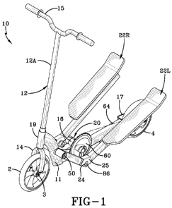
Fig. 1 shows a perspective view of the scooter made according to a first
embodiment of the invention.
Fig. 2 is a side view of the scooter of figure 1.
Fig. 2A is a top view of the scooter of figure 1.
Fig. 3 is an exploded view of the drive mechanism assembly of the scooter.
Fig. 4 is a perspective view of the assembly drive mechanism assembly.
Fig. 5 is a plan view of the drive mechanism attached to the frame of the
scooter.
Fig. 6 is a perspective view of the foot pedals attached to the drive
mechanism.
Fig. 7 is a perspective view of the foot pedals and drive mechanism attached
onto the frame.
Fig. 7A is a plan view of foot pedals and drive mechanism on the frame of
figure 7.
Fig. 8 is a perspective view of a second embodiment of the invention showing
a two chain drive assembly with an additional intermediate bottom bracket.
WO 2011/028861 CA 02809964 2013-02-28PCT/US2010/047618
-5-
Fig. 9 is a side view of the scooter of figure 8.
Fig. 9A is a top view of the scooter of figure 8.
Fig. 10 is a plan view of the second embodiment modified with a bicycle
derailleur attached to the rear hub with a shift mechanism.
Fig. 11 is a table showing gear and tire sizes and expected performance
speeds.
DETAILED DESCRIPTION OF THE INVENTION
[0010] With reference to figures 1, 2 and 2A, an improved pedal drive scooter
10 is
illustrated. The scooter 10, as shown in figure 1, has a frame 11 including a
handlebar
assembly 12 including the handle bar grips 15, a shaft 12A which extends
through and
is secured to a hub 19 on the frame 11 of the scooter 10. The shaft 12A
extends below
the hub 19 to a forked portion 14 which is secured to an axle 3 on the front
wheel 2 of
the scooter 10. The steering assembly 12 allows the front wheel to be
maneuvered for
steering and turning. The frame structure 11 extends from the hub 19
rearwardly to a
yoke 17 which connects the rear wheel 4 to the frame 11. As illustrated in
figure 5, the
frame 11 has a step down portion which is connected to the hub 19 and extends
substantially downwardly to the bottom of a frame 11 to which a main frame
support bar
13 is attached. As shown, at the attachment of the main support bar 13 to the
step
down portion 9 of the frame, a supporting gusset 8 is welded providing
additional
strength and stiffness at this location. Welded onto the main support bar 13
is a bottom
bracket 16, this bottom bracket 16 provides a location for a drive mechanism
20
assembly to be mounted. The drive mechanism 20, as illustrated in figure 2A,
includes
a drive sprocket 60. Attached to the drive sprocket 60 is a drive chain 64
which
extends rearwardly back to the rear wheel sprocket 59. The sprocket 59 is
attached to
the axle 5 of the rear wheel 4 and as the device is operated, turns the rear
wheel 4
providing forward propulsion.
[0011] Attached to each side of the frame 11, as illustrated in figures 1, 2
and 2A, are
a pair of foot pedals 22R and 22L. The foot pedals 22R and 22L are attached to
the
frame 11 at location 50. This location 50 will be referred to hereafter as the
proximal
WO 2011/028861 CA 02809964 2013-02-28PCT/US2010/047618
-6-
hinge attachment location 50. The foot pedal 22L is a mirror image of the foot
pedal
22R. These foot pedals operate in reciprocating motion, up and down and are
connected to the sprocket 60 to provide forward propulsion. As the pedals are
moved
in an up and down direction, the sprocket 60 is rotated moving the chain 64
which in
turn moves the rear sprocket 59, and propels the rear wheel 4.
[0012] For a better understanding of the drive mechanism 20, an exploded view
is
illustrated in figure 3. This drive mechanism 20 is connected to an axle 18.
The axle
18 has a pair of splined ends 19. Over the axle 18 a pair of bearings 87 are
inserted,
these bearings 87 are pressed onto the axle or slipped over the axle and
extend to the
shoulder of the axle 18 as illustrated. A washer or bushing 88 is shown
attached on the
axial outer side of each bearing 87. A shoulder bushing 92 is then placed next
to the
bushing 88. A washer 93 is attached onto the shoulder bushing 92 and the
sprocket 60
is then positioned onto the shoulder bushing 92 and washer 93. The sprocket 60
includes a locating hole 94 to which the crank lever link 31R is positioned
with the
splined opening 34 aligned with a center hole on the sprocket 60 and an
integral
projection or pin 89 on the crank link 31R is fitted into the hole 94 to
securely
rotationally lock the crank link 31R to the sprocket 60. All of these
components are
then slid over the splined end 19 of the axle 18 and the opening 34 of the
crank link
31R is pressed onto the splined end 19 of the axle 18. As further illustrated,
a washer
91 is inserted into the crank link 31R and a threaded fastener 90 is screwed
directly into
the axle 18 at the threaded opening in the splined portion 19. As further
illustrated, a
coupling link 32 is then attached to the crank link 31R at threaded opening
35. In order
to make this assembly, the coupling link 32 at the lower end has a bushing 42
that is
inserted into one side of the coupling link 32, a bearing 43 is positioned
into the
coupling link opening on the opposite side and a sleeved bushing 46 is
inserted into the
bearing 43 through which a threaded fastener 44 is inserted and threadingly
engaged
into the threaded opening 35 of the crank link 31R or 31L, securing the
coupling link 32
to the crank links 31R or 31L. A pedal attachment link location at the other
end of the
link 32 is shown wherein a threaded sleeved element 82, a washer 83 and a
bearing 43
are shown inserted into the opening of the coupling link 32 and a sleeve 84 is
shown
that slides over the sleeved portion 82 in such a fashion that a fastener 86
can then
threadingly engage the component 82 to secure this assembly of components.
Prior to
securing the fastener 82, the pedals will be attached over the sleeve 84 and
held in
place by fastener 86 as will be discussed and shown later. The assembly method
of the
drive mechanism components can vary in sequence, however, it must be
understood
WO 2011/028861 CA 02809964 2013-02-28PCT/US2010/047618
-7-
the axle 18 has to have at least one end free to be slid into the bottom
bracket 16 of the
frame prior to attaching the various components.
[0013] The coupling link assembly 30L is illustrated having identical
components to the
coupling link 30R, as shown, coupling link 32 is attached to the crank link
31L, as
illustrated. As shown, the crank link 31L has a bearing 87, a washer 88
attached onto
the opposite splined end 19 of the axle 18, and the crank link 31L is then
assembled
onto the splined end 19 of the axle 18, a washer 91 is inserted into the
opening 34 and
the threaded fastener 90 is then used to attach the crank link 31L directly to
the axle 18,
as illustrated. The entire assembly is illustrated in figure 4; this drive
mechanism 20 is
shown secured in the bottom bracket 16 shown in phantom lines.
[0014] With reference to figure 5, the drive mechanism 20 is shown mounted
onto a
portion of the frame 11, with the pedals not yet attached.
[0015] With reference to figure 6, the foot pedals 22L and 22R are shown
attached to
the drive mechanism 20 and when assembled form the primary drive mechanism 20
for
the scooter 10.
[0016] The foot pedal 22L is a mirror image of the foot pedal 22R, as
illustrated in
figure 7, the foot pedals each have a platform 28 that can include a primary
flat surface
upon which a foot can rest. At the rearward end of the foot pedal platform 28,
the
platform can be bent or angled slightly upwardly forming a heel stop portion
29 in order
to provide a location for the rider's heel to be supported. This gives the
rider an easy
way to appreciate his foot location relative to the pedal platform 28. This
also provides
an optimum location for maximizing the amount of pedal power the rider has in
order to
have a good mechanical leverage in driving these pedals in a downward motion
to
propel the scooter 10. The foot pedal 22L or 22R includes a long main shaft 21
which
extends from the underside of the foot pedal platform 28 forward to a coupling
joint 25.
The coupling joint 25 has the main shaft 21 attached on one side and has a
short
angled portion 23 connected to the opposite side. At the end of the short
angled portion
23 is a cylindrical hub 27, this cylindrical hub 27 provides an attachment
location for
assembly to the frame 11. The connecting portion 25 is located precisely at
the
intersection or bend between the main shaft portion 21 and short angled
portion 23 and
provides a reinforced pedal attachment location 24 for assembly to the
coupling link 32.
This attachment location 24 connects the foot pedal 22L or 22R directly to the
drive
mechanism 20. When assembled to the frame 11, as illustrated in figure 7, the
proximal hinge location 50 is shown wherein a threaded fastener connects the
hub 27
WO 2011/028861 CA 02809964 2013-02-28PCT/US2010/047618
-8-
of the pedal 22L or 22R directly to the frame 11 in the step-down portion 9 of
the frame
11.
[0017] With reference back to figure 2, this assembly when completed as shown
creates a virtual four bar linkage drive mechanism whereby the distance
between the
proximal hinge location 50 extends to the intersection at or near the bend to
the
reinforced pedal attachment location 24 and extends a distance P, as
illustrated. A
virtual frame link is created between the proximal hinge location 50 of the
frame 11 and
the axis if rotation or center of the axle 18 of the drive mechanism 20. This
virtual
frame link distance is illustrated as a dimension F. The two ends of the frame
link are
fixed in location and do not move except rotationally relative to the other.
As the pedals
22L and 22R reciprocate up and down, the coupling links 32 and the crank links
31L
and 31R rotate along with the sprocket 60. As illustrated, the coupling link
32 extends
from the pedal attachment location 24 back to a pin location connecting the
coupling
links 32 and the crank link 31L or 31R. This dimension is identified as C2.
Extending
from the coupling link pin location and crank attachment, a distance of Cl is
illustrated
extending back to the drive axle 18 and the sprocket 60. It is important to
note that the
coupling link dimension C2 is substantially larger than the crank link
dimension Cl, as
illustrated in figure 2. Preferably the coupling link dimension C2 is
approximately 150
percent of the dimension Cl, furthermore, it is noted that the proximal hinge
location 50
attaching the foot pedal 22L or 22R to the frame 11 extends vertically,
preferably,
above the drive axle 18 location. This vertical distance is indicated as Yin
figure 2.
[0018] With further reference to figure 7A, what is achieved by providing foot
pedals
22L and 22R with a bent angled portion 23 attached to a step-down portion 9 on
the
frame 11 is that when a foot pedal in a full bottom position as illustrated
can be made
substantially horizontal relative to the ground. This enables the foot pedal
in the bottom
stroke to be in the most comfortable position relative to the rider. As can be
seen, the
foot pedals 22L, 22R provide the driving force of the sprocket 60. As
illustrated in figure
7A, when one foot pedal 22L is in the full bottom position, the opposite foot
pedal 22R
is shown in the maximum stroke position a. As illustrated, the maximum stroke
position
has a stroke angle a of approximately 29 degrees. This means that as the rider
reciprocates the pedals 22L or 22R in an upward and downward motion, the
stroke
angle is always less than 30 degrees and this means the downward force is
maximized
and enables the rider to more easily propel the vehicle 10. As further
illustrated, due to
the fact the rider's foot is positioned close to the inclined heel location
portion 29, the
downward driving force is greatly exaggerated due to the mechanical advantage
WO 2011/028861 CA 02809964 2013-02-28PCT/US2010/047618
-9-
achieved by the long main shaft 21 relative to the short bar 23. This provides
a
significant mechanical advantage such that the crank link 31L, 31R and
coupling links
32 can be rotated achieving a maximum leverage force advantage. This creates
additional torque and facilitates the rider's ability to propel the vehicle.
[0019] As shown, a significant advantage of the foot pedal mechanism employed
with
this improved scooter 10 is that the foot pedals 22L and 22R can be positioned
at or
below the wheel axles and due to the step-down frame design the ground
clearance of
the pedals 22L and 22R is relatively independent of the wheel size. In other
words, the
extending short portion 23 can be positioned such that the entire foot pedal
in the
bottom stroke position will be at or below the location of the frame and can
be made
substantially at or below the wheel axle position if so desired. This means
that the
vehicle has an extremely low center of gravity which provides additional
stability to the
rider, as such he or she will be able to maneuver the scooter with improved
stability due
to the fact that the rider maintains a low center of gravity during operation
of the vehicle.
[0020] The above description describes an improved scooter 10 having a single
drive
sprocket 60 connected to a rear wheel sprocket 59 to provide propulsion for
the vehicle.
In this combination, the action of the pedals 22L and 22R and the movement of
the rear
wheel 4 are dependent on the ratio of gear sizes of the front drive sprocket
60 and the
rear sprocket 59 such that the rotation of the forward sprocket 60 based on
the
downward stroke of the pedal 22L or 22R rotates the rear sprocket 59 by a
multiplying
factor if the front sprocket 60 is substantially larger than the rear sprocket
59. The front
sprocket 60, when moved by a pedal 22L or 22R, will rotate the rear sprocket
59
substantially faster in terms of angular rotation thus causing the rear wheel
4 to move
proportionately faster than the rotation occurring at the front sprocket 60.
The ability to
achieve a mechanical advantage between the sprockets is based on the ability
to select
sprockets of different sizes and creating different gear ratios between the
front 2 and
rear 4 wheels. The first embodiment provides a simple way of achieving an
improved
scooter device with adequate vehicle speed performance using a single chain
64.
[0021] With reference to figures 8, 9, 9A, and 10, a second embodiment scooter
10A is
illustrated. The second embodiment scooter 10A employs not only a first
sprocket 60
and a first bottom bracket 16, but an intermediate sprocket assembly 62
wherein the
intermediate sprocket assembly 62 is connected to an intermediate small
sprocket 61
on the same side of the first drive sprocket 60 and is connected to the first
drive chain
64, as illustrated. An intermediate bracket hub 16A is provided with an axle
18A
internal of the intermediate bracket hub 16A such that the intermediate
sprocket 61 can
WO 2011/028861 CA 02809964 2013-02-28PCT/US2010/047618
-10-
be connected directly to the intermediate sprocket 62 on the opposite side of
the frame
11. The sprocket 62 is connected through a second chain 66 back to the rear
drive
sprocket 59, as illustrated. Fundamentally, all the other components used in
the single
chain driven scooter 10 are utilized in the two chain scooter 10A. In this two
chain
scooter 10A, an additional gear ratio multiplier advantage can be achieved
wherein the
first drive sprocket 60 can rotate a small intermediate sprocket 61 which then
in turn
can drive a larger intermediate sprocket 62 which is connected to a second
chain 66
which is then connected to a smaller rear sprocket 59, as illustrated. When
this occurs,
propulsion of the foot pedals 22L and 22R rotates the first drive sprocket 60
through the
first chain 64 rotating the smaller intermediate sprocket 61 at a
substantially faster
rotational speed due to the smaller gear size and the second larger
intermediate
sprocket 62 is then rotated at this higher speed which then in turn causes the
smaller
rear sprocket 59 to rotate at even a higher speed. As a result, the rider with
the same
stroke used in the first embodiment scooter 10 can with the gear ratios
properly
selected can more than double the speed achieved using the same stroke and
energy.
[0022] As shown in the table of figure 11, the various speeds for different
gear teeth
ratios are shown based on a pedal stroke of 50 per minute for different tire
sizes. As
shown in the table, if the gears T2, T3 and T4 are the same then the table
works for the
scooter 10 having a single chain drive 64. If the ratios of T2, T3 and T4 are
different in
and one of the these gears that indicates it is the scooter 10 with a dual
drive chain
assembly.
[0023] An important factor in this second embodiment is that the physical
dimensions
of the four bar linkage system in relation to the frame can be maintained
identical to that
of the first embodiment. The dimensions F for the virtual frame length, P for
the
distance between the proximal hinge location 50 and the pedal attachment
location 24,
the distance C2 of the coupling link and the distance Cl of the crank link to
the axle 18
are all maintained identical to those of the first embodiment. In addition,
the distance of
the proximal hinge location 50 vertically relative to the axle 18 is also
maintained at the
distance Y as previously discussed. These factors enable the mechanical
advantage
and leverage that the rider enjoys and the low center of gravity to be
maintained in this
dual chain driven assembly shown in scooter 10A.
[0024] In the best mode of practicing the invention, the dimensions F, P, Cl
and C2
where set at 175.0 mm, 155.6 mm, 38.4 mm and 63.5 mm respectively. These
dimensions, it was determined provided an extremely smooth movement of the
drive
mechanism. Furthermore, by rounding of these dimensions at 175 mm, 156 mm, 38
WO 2011/028861 CA 02809964 2013-02-28PCT/US2010/047618
-11-
mm and 64 mm, it was determined satisfactory performance was achieved wherein
one
or more of these dimensions were adjusted within plus or minus 2 mm of the
settings;
more preferably within plus or minus 1 mm. These dimensional locations of F,
P, Cl
and C2 were found to work well when Y was set at 50 mm plus or minus 4 mm,
preferably within plus or minus 2 mm, and Z was set at the same dimension as F
of 175
mm within plus or minus 4 mm, preferably within plus or minus 2 mm.
[0025] An important aspect of the dimensional positioning of the four bar
linkage is
proper rotation of the coupling link 32 and the crank lever 31L or 31R. If the
locations
are not accurately located, the drive mechanism can lock up wherein a lock up
phenomena is understood to occur at a top dead center location causing the
links to
bind, stopping the pedals from moving. A worse problem can occur wherein the
linkages can actually reverse rotational direction. In this case a pedal can
abruptly
slam down as the links rotate opposite to their normal or desired movement.
The
present invention avoids these issues entirely by a proper selection of four
bar link
dimensions F, P, Cl and C2. These problems, while understood to exist, were
not fully
appreciated. Computer software which models and predicts dimensions for four
bar
linkage systems relies on the axle 18 to be the driving location and as such
the
predicted optimal locations for such a device acted perfectly when one rotated
at the
axle by hand, but when the drive propulsion was moved to the location 24, as
in the
actual scooter device, these software optimum solutions would not operate
properly. It
was determined that each of the link dimensions and the relationship of C2
being
greater than Cl by at least 150 percent and the proximal hinge location were
all critical.
This meant finding optimal dimensions was not predictable using standard
software
generated solutions. The performance of the present invention was greatly
enhanced
by the selection of the link dimensions and attachment locations on the frame
11. The
solution found in the present invention allows for the dimensions to deviate
slightly
within normal manufacturing tolerance without the lock up or reversal issues
that
previously existed in the drive mechanism design.
[0026] In each of the embodiments, the scooter 10 and the scooter 10A it is
understood that between the pedals 22L and 22R a chain guard or chain cover
(not
illustrated) will be provided in order to provide additional safety for the
rider. These
component features are not illustrated in order to provide a clear view of the
driving
mechanism 20 of the present invention and the unique pedal design coupled to
the
drive mechanism and frame structure of the vehicle including its unique step-
down
frame design and low center of gravity features.
WO 2011/028861 CA 02809964 2013-02-28PCT/US2010/047618
-12-
[0027] The scooter 10A as illustrated in figures 8-9, further can be improved
by the use
of a derailleur 110 on the rear wheel assembly such that multiple gear ratios
can be
provided such that the rider can be able to switch gears from a low gear to a
high gear
as one increases speed. This alternative embodiment addition shown in figure
10 to
the device of scooter 10A is provided to show how even further enhanced speed
achievements can be accomplished with the use of the present invention in
combination with a bicycle type derailleur 110. As mentioned, each of the
embodiments can be equipped with a free rolling clutch internally mounted
inside the
bottom brackets 16, 16A or the rear hub of the wheel such that in any of those
locations
the chains 64, 66 will be permitted to free wheel or coast such that the
pedals do not
have to be operated while the vehicle is in motion, providing a coasting or
relaxing
mode for the driver. Only when the pedals are pushed in a downward motion will
the
forward movement of the rear wheel 4 be driven by the driving mechanism,
otherwise,
on downhill slopes, the vehicle can be set such that the rider can coast down
a hill. It is
understood as these vehicles approach higher speed capabilities they can be
provided
with handlebar brakes that can be used on the front or rear wheels to slow the
vehicle
down if so desired. These and other features can be provided and are
considered
within the scope of the present invention.
[0028] The invention as described herein is directed to a scooter, as used
herein, a
scooter is a vehicle having typically two wheels, but could have three, but is
so
designed to have the rider standing on the pedals. The use of pneumatic tires,
solid
rubber or urethane tires does not change the device from a scooter to a
bicycle. It is
understood, however, the present invention with the addition of a seat for the
rider,
would take on the appearance of a pedal drive bicycle, as such the use of the
present
invention with a seat would also be considered within the scope of the present
invention, but it must be appreciated that the maximum driving speed of the
rear wheel
is most easily performed standing.
[0029] Variations in the present invention are possible in light of the
description of it
provided herein. While certain representative embodiments and details have
been
shown for the purpose of illustrating the subject invention, it will be
apparent to those
skilled in this art that various changes and modifications can be made therein
without
departing from the scope of the subject invention. It is, therefore, to be
understood that
changes can be made in the particular embodiments described which will be
within the
full intended scope of the invention as defined by the following appended
claims.