Note: Descriptions are shown in the official language in which they were submitted.
CA 02809967 2013-03-18
POWER DISTRIBUTION SYSTEM AND METHOD FOR LED LIGHTING
FIELD
This present disclosure relates generally to a power distribution system and
method for light
emitting diode (LED) lighting.
BACKGROUND
Large scale controllable LED lighting applications such as lighting for
architectural delineation
for skyscrapers, bridges, airports and shopping malls and other mission
critical applications
require high system reliability, and long service life. Additionally, such
applications desire small
luminaire size and long luminaire run length from single power connection
point.
However, existing power distribution systems for LED lighting suffer from
limitations including
limited life, larger luminaire dimensions, limited lighting length and limited
system life.
What is needed is an improved power system and method for LED lighting which
overcomes at
least some of these limitations.
SUMMARY
This present disclosure relates generally to an improved AC line supplied LED
lighting power
distribution system and method, in which the required power conversion
components,
specifically electromagnetic interference (EMI) filter, rectifier, and power
factor corrector (PFC),
are located remotely from luminaires, enabling smaller luminaire size, and
keeping the
advantages of the high voltage power distribution system.
Additionally, the disclosed power distribution current is limited to
reasonable ranges in order to
maintain desirably small physical dimensions. The disclosed power distribution
system delivers
sufficient total power by significantly increasing the system voltage above
the peak input line
voltage (e.g. 110VAC in North America).
In an illustrative embodiment, which is not meant to be limiting, a system is
designed around
AWG18 conductors with current limited to 10A, and voltage at around 380VDC to
allow
lighting circuits to be built with up to 3,800W fed from a sing power/data
source.
CA 02809967 2013-03-18
With the present system and method, LED lighting lengths of 200 meters or more
may be
configured providing exceptionally long runs of LED lighting for large scale
LED lighting
applications such as the architectural delineation for skyscrapers and
bridges.
In this respect, before explaining at least one embodiment of the invention in
detail, it is to be
understood that the invention is not limited in its application to the details
of construction and to
the arrangements of the components set forth in the following description or
illustrated in the
drawings. The invention is capable of other embodiments and of being practiced
and carried out
in various ways. Also, it is to be understood that the phraseology and
terminology employed
herein are for the purpose of description and should not be regarded as
limiting.
BRIEF DESCRIPTION OF THE DRAWINGS
FIG. 1A shows a schematic block diagram of a conventional AC LED lighting
system with
inboard power distribution
FIG. 1B shows a schematic block diagram of a conventional AC LED lighting
system with low-
voltage power distribution.
FIGS. 2A and 2B show an illustrative schematic block diagram of the disclosed
power
distribution system for LED lighting utilizing a power-data box in accordance
with an
embodiment.
FIGS. 3A and 3B show illustrative perspective views of one possible physical
embodiment of the
DC LED lighting system of FIGS. 2A and 2B.
FIGS. 4A and 4B show illustrative plan views and perspective views of another
possible physical
embodiment of the DC LED lighting system of FIGS. 2A and 2B.
FIGS. 5A and 5B show illustrative plan views and perspective views of yet
another possible
physical embodiment of the DC LED lighting system of FIGS. 2A and 2B.
In the drawings, embodiments of the invention are illustrated by way of
example. It is to be
expressly understood that the description and drawings are only for the
purpose of illustration
and as an aid to understanding, and are not intended as a definition of the
limits of the invention.
2
CA 02809967 2013-03-18
DETAILED DESCRIPTION
As noted above, the present disclosure relates generally to an improved power
distribution
system and method for LED lighting, especially for large scale LED lighting
applications such as
lighting for architectural delineation for skyscrapers, bridges, airports and
shopping malls and the
like.
Prior art technologies are based on two common approached to power
distribution:
1. Low-voltage DC power distribution ¨ power supply converting AC to low
voltage DC is
located remotely from luminaire. Each luminaire is powered by low voltage DC
power.
2. Inboard luminaire power integration ¨ power supply is integrated with
luminaire,
enabling high voltage distribution but large luminaire dimensions.
A low voltage DC distribution system is not suitable for lighting significant
lengths due to
electric current limitations, as specified by Class 2 electrical code. The LED
lighting lengths , for
example at 5Watts/foot (1foot = 0.3048 meters) can be extended only 20 feet or
so assuming
5W/ft power consumption to stay within Class 2 specifications.
An inboard luminaire power system, where the AC/DC power supplies are
integrated with LED
luminaires, enables extended run lengths (e.g. 50-60ft at 110VAC, and 100ft at
220VAC),
however the physical dimensions of luminaires are increased due to the
presence of EMI,
rectified and PFC power conversion components within the luminaire.
Additionally, the overall
system reliability is dictated by the shortest lifespan of inboard components.
Typical
embodiments of this approach rely on electrolytic capacitors which have an
order of magnitude
shorter lifespan than other components of the system. Also, the lighting run
lengths remain
capped because they are based on fixed input AC line voltage (110VAC or 220VAC
depending
on the geographical region).
The present system and method was developed by the inventors to address the
issues of
component size, while maintaining sufficient brightness over long lighting
lengths. More
particularly, the inventors proposed a power distribution system in which the
required power
conversion components, specifically EMI filter, rectifier, and PFC, are
located remotely from
3
CA 02809967 2013-03-18
luminaires, enabling smaller luminaire size, and keeping the advantages of the
high voltage
power distribution system.
Additionally, the inventors made a decision to limit the current to a suitable
level in order to be
able to use sufficiently small gauges of conductive wires, and by
significantly increasing voltage
over conventional household line voltages (e.g. 110VAC in North America, and
220VAC in
Europe and other regions) to allow for adequate power.
As an illustrative example, which is not meant to be limiting, a system is
designed around
AWG18 conductors with current limited to 10 Amps, and voltage at around 380VDC
to allow
lighting circuits to be built with up to 3,800W fed from a sing power/data
source. With the
present system and method, LED lighting lengths of 200 meters or more may be
configured
providing exceptionally long runs of LED lighting for large scale LED lighting
applications such
as the architectural delineation for skyscrapers and bridges. To generate the
high voltages
necessary, the present system and method utilizes a power-data box comprising
a filter, bridge
and a PFC as a power source, replacing multiple PFC modules in each lighting
module with a
single PFC provided in the power-data box.
Various illustrative embodiments are described with respect to the figures.
Referring to FIG. 1A, shown is a schematic block diagram of a conventional AC
LED lighting
system with inboard power distribution 100 including a line filter 110
connected to ground and
to an AC line including line and neutral. The AC line provides a typical AC
line voltage (e.g.
110VAC in North America, 220VAC in Europe and in other regions). The AC line
voltage can
also be supplied from 2 or 3 phase power systems. As shown, line filter 110 is
operatively
connected to a rectifier 120, which in turn is connected to a power factor
correction ("PFC")
module 130. The rectifier 120 converts an input AC line voltage source to a DC
voltage at value
Vac*SQRT(2), where Vac is the root mean square value of the AC line voltage.
PFC 130
provides power factor on the AC line close to 1.0 and its output voltage (for
a boost type of PFC)
is at least a few volts higher than DC voltage from the rectifier 130 (180VDC
at AC line voltage
110VAC; 260VDC at AC lien voltage 220VAC and 430VDC at universal AC lien
voltage
70VAC to 305 VAC). Notably, using any step-down type of PFC (for example buck,
buck-boost,
etc.) is a problem for red green blue (RGB) color changing types of LED
luminaries for various
reasons. A bus voltage Vbus from PFC 130 supplies LED module 140. An optional
DC/DC
4
CA 02809967 2013-03-18
driver 145 may be provided between PFC 130 and LED module 140 to down convert
to a
voltage suitable to the LED module 140. A control 150 is adapted to receive a
data signal from
the data line to control DC/DC driver 145 and/or PFC 130.
Referring to FIG. 1B, shown in a schematic block diagram of another
conventional AC LED
lighting system with low-voltage power distribution. As shown, line filter
110, rectifier 120 and
PFC 130 supply a high voltage to a DC/DC converter 135 in a conventional power
box. DC/DC
converter 135 provides low voltage power to one or more luminaires, including
a DC/DC driver
145, control 150, and an LED 140. The low voltage power provided to the one or
more
luminaires necessitates a correspondingly high current in order to drive the
one or more
luminaires at sufficient brightness. To handle the higher current, a thicker
gauge wire is required
in order to extend the length of the wires providing the low voltage power.
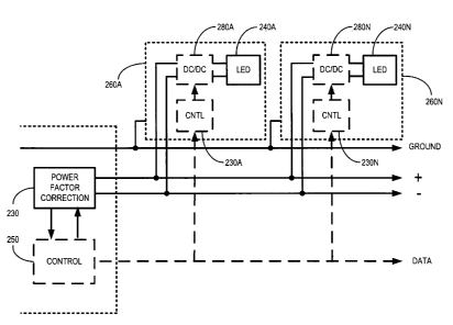
Now referring to FIGS. 2A and 2B, shown is an illustrative schematic block
diagram of a DC
LED lighting system 200 utilizing a power-data box in accordance with an
embodiment. As
shown in FIG. 2A, in an embodiment, the DC LED lighting system 200 includes a
power-data
box 202, which includes a line filter 210 connected to ground and to line and
neutral of an AC
line. Power data box 202 further includes a rectifier 220, a PFC module 230,
and a control unit
250.
FIG. 2B shows PFC 230 and control 150 from FIG. 2A, and further shows ground,
+ and ¨ lines
from PFC 130, and data lines extending from power-data box 202. As shown in
FIG. 2B, one or
more luminares 260A..260N are connected to ground, the + and ¨ lines of PFC
130, and to the
data line. More particularly, each LED module 260A..260N includes individual
LEDs
240A. .240N and an LED module control 230A. .230N adapted to receive data from
main control
unit 250. Each of the LED module controls 230A. .230N may be used to control
the current and
brightness of individual LEDs 240A. .240N, and may be collectively controlled
via the main
control unit 250 to generate various lighting patterns.
As shown in FIG. 2B, LED luminaires 260A..260N need not contain individual
PFCs 130 as in
FIG. 1, as the LEDs 240A. .240N are connected to PFC module 230 in the main
power data box
202. This significantly decreases the number of components required in LED
modules
240A..250N. Optional LED module controls 230A..230N connected to optional
DC/DC drivers
5
CA 02809967 2013-03-18
280A. .280N may be addressable to individually receive data from main control
unit 250 or to
receive data broadcast to all LED module controls 230A. .230N.
In an embodiment, the gauge or cross-section area of the conducting wires used
to connect LED
luminaires 260A. .260N may be selected much les than for conventional AC LED
lighting system
100 (FIG. 1) due to the limited current, and output voltage from PFC 230 being
significantly
higher than AC line voltage used in conventional AC LED lighting system 100.
More preferably, the gauge of the conducting wires used to connect LED
luminaires 260A. .260N
may be selected to be between American Wire Gauge (AWG) AWG24 and AWG14, and
the
current may be limited between 5 and 30 Amps, such that the size of the LED
luminaires
260A. .260N can be limited to desirably small dimensions.
Most preferably, the gauge of the conducting wires used to connect LED
luminaires 260A. .260N
may be selected to AWG18, and the current may be limited to 10 Amps, such that
the size of the
Luminares 260A. .260N can be limited for use in illustrative examples as shown
in FIGS. 3 ¨ 5 as
described further below.
In an embodiment, power-data box 202 is adapted to supply a DC voltage
significantly higher
than conventional line voltage, in an operable range up to 430 VDC.
More preferably, power-data box 202 is adapted to supply a DC voltage between
a range of 100
and 400 VDC, such that power-data box 202 can generate a sufficiently high
level of power to
supply power to individual LEDs 240A. .240N for significant lengths.
Most preferably, power-data box 202 is adapted to supply a DC voltage between
a range of about
200 and 380 VDC, such that power-data box 202 can generate up to 3,800 Watts,
which can be
used to supply power to individual LEDs 240A. .240N rated at between about 1
and 100 Watts,
connected at appropriate intervals depending on the Wattage of the LEDs 240A.
.240N, over
lengths of conductive wires extending 200 meters or more.
In an embodiment, Table 1 below shows possible lighting lengths in meters
achievable when the
power-data box 202 is capable of generating 2,000 Watts and 3,800 Watts and
5,000 Watts of
power utilizing 110VAC or 220-240VAC input line voltages.
6
CA 02809967 2013-03-18
STR9-INF
INPUT
POWER-DATA-BOX HL-DL HL-COVE
VOLTAGE 25 50
Watts/meter Watts/meter
P DB-2000 90-199VAC 110 110 39 20
P DB-2000 200-264VAC 60 60 73 36
PDB-3800* 90-264VAC 201** 201** 142 72
P DB-5000* 90-264VAC 201** 201** 182 93
Table 1
** For the color mixing version requiring three control channels to
independently control three
colors (for example red, green, and blue)version, the maximum length is 341
feet for 1 foot
addressability (limited by DMX control universe, which can only address 241
three color pixes),
full length for three channel control requires two DMX control universes.
Now referring to FIGS. 3A and 3B, shown are illustrative perspective views of
one possible
physical embodiment of the DC LED lighting system of FIGS. 2A and 2B. FIG. 3A
illustrates a
length of lighting which may include a number of lighting unit modules
connected in series. As
shown in FIG. 3B, three lighting unit modules are connected in series and
covered by a
delineation diffuser, which may be acrylic for example. A mounting profile,
which may be
aluminium for example, receives the three lighting unit modules and together
with the
delineation diffuser provides a protective, fully sealed IP66 300millimeters
(nominally 1 foot)
luminaire with 18 LEDs. In use, each lighting unit module snaps into place in
the aluminium
profile, which is securely fastened to a mounting surface. The three lighting
unit modules are
connected end-to-end within the profile to create linear runs. The acrylic
diffuse, with
specialized light diffusing and UV stabilizing additives, installs to the
profile, over the LED light
modules. The diffuser conceals all mounting provisions, and provides a clean,
uniform
illuminated surface.
7
CA 02809967 2013-03-18
Still referring to FIG. 3B, a first end of the first lighting unit module is
connected by a power-
date leader cable to a power-data box shown in the foreground. The power-data
box include a
line voltage input, which may be between about 84-347VAC. The power-data box
also receives
a control input line, and a control output leads out of the power-data box to
be connected to the
lighting unit modules in order to control the individual LED modules.
As shown in Table 2, below, this illustrative embodiment shown in FIGS. 3A and
3B allows
exceptionally long runs of up to 201meters with a single power and data feed
from the power-
data box.
Specification Logic
HL-DL CM - Clear Matte ROB ND - No Dimming XXX
CUSTOM 2700K DMX DMX Control
3000K DAL1 DALI Control
3500K ARTNET - ARTNET Control
4000K 0-10V - 0-10V Dimming
5000K
6500K
RD - Red
OR - Green
- Blue
Length should be in 1ft or 0.3m increments
Sample Logic: HL-DL-CM-RGB-DMX-102M
Table 2
Now referring to FIGS. 4A and 4B, shown are illustrative plan views and
perspective views of
another possible physical embodiment of the DC LED lighting system of FIGS. 2A
and 2B.
As shown in FIG. 4A, this illustrative embodiment comprises a long-run modular
LED lighting
system designed for cove lighting applications where it is impractical to have
numerous power
feed points. Typical applications include architectural cove lighting and
delineation where long
runs are necessary and limited power feeds are available. Exceptionally long
runs of up to 201
meters are achievable with appropriate power-data-box.
In the present embodiment, the system consists of LED modules and
corresponding mounting
profiles. Each LED module is a fully sealed, IP66, 300mm (1foot) linear
luminaire with 10
LEDS. Each module snaps into the mounting profile, which is securely fastened
to the mounting
8
CA 02809967 2013-03-18
surface. Modules are installed and connected end-to-end to create linear runs.
Table 3, below,
provides some illustrative LED lighting color and control specifications.
Specification Logic
HL-COVE RGB ND - No Dimming XXX
2700K WAX DMX Control
3000K DAL! DALI Control
3500K ARTNET ARTNET Control
4000K 0-10V - 0-10V Dimming
5000K
6500K
RD-Red
DR - Green
ILL - Blue
* Length should be in lft or 0.3m increments
Sample Logic: FIL-COVE-RGB-DMX-300F1
Table 3
Now referring to FIGS. 5A and 5B, shown are illustrative plan views and
perspective views of
yet another possible physical embodiment of the DC LED lighting system of
FIGS. 2A and 2B.
This illustrative embodiment is a high-power, long-run, linear LED luminaire
designed for wall
"washing", wall "grazing" and cove lighting. Typical applications include
"Architainment",
facade, bridge, airport, and shopping malls, particularly in large
installations requiring long runs
where multiple feeding points are not desirable or allowed. The system allows
the LED modules
to be connected end-to-end in exceptionally long runs (e.g. 182 meters at 25
Watt/meter
consumption is achievable with a 5,000W power-data-box. In an embodiment, IP68
rated
connectors may be used to provide sealing even when unmated.
The LED modules are sealed to provide 1P66 rated weatherproofing, and provides
compact size,
making it virtually invisible on the structure to which it is installed. The
thermal design is
effective in hot and humid climates as well as severe northern winters. Table
4, below, shows
9
CA 02809967 2013-03-18
Specification Logic
1
STR9.1NF 600 . CM = Clear Matte 6 1W 2700K TB = Tight Boom
(fl= FWHM) j ND- No Dimming, On/Off 320VDC . 5/4 - Surface Mami Adjustable
900 IM- Black Matte 2.5W 3000K NO - Narrow Boom (12.
FWHM) J ZH - GM Protocol 211 7,0;D( W33 - Wall Mow* Adjustable 38nan
1200 j 35000 MI - Medium Boom po. FWHM) j
.iNv .., W73 - Wall Mount Adjustable 713mm
1500 ; 40001( WI- Wide Beans (54" FWHM) .
W131 = Wall Mount Adjustable 131mm
i .=. = 5000K Fl - Hood Seam 170 FWHA9 J
. j
Will . Walt Mount Adjustable 127mm
,
= , . 65000 ER = Elliptical acorn (12" x 46" FNMA l
= RD - Red AN -
Asymmericol Narrow .
RO - Red-Orange Al - Asymmetrical Elliptical i
AM - Amber .
: OR - Omen
IL - Ble.i.
. RI- Royal Blue .
Sample Logic i STR9-INF.1500-CM-6-2W1-30000-NB-ZH-3110VDC
Table 4
While various illustrative embodiments have been described, it will be
appreciated that various
modifications and changes may be made without departing from the scope of the
invention.