Note: Descriptions are shown in the official language in which they were submitted.
A CASE FOR ENCLOSING
A PERSONAL ELECTRONIC DEVICE AND A CARD
[0001]
FIELD OF THE INVENTION
[0002] The present invention relates to a case for enclosing a personal
electronic device
and one or more cards, such as credit cards, payment cards, coupons, receipts,
identification cards, merchandise credit cards, gift cards, or business cards.
BACKGROUND
[0003] Cases for phones, sometimes known as portfolio cases, that carry a
personal
electronic device and several credit cards arc similar to a traditional wallet
and typically
have two sides, one that holds the cards and one that holds the personal
electronic device,
that are folded over one another. Known drawbacks for these types of cases
include their
expense, bulk, (adding to 5 mm or more to each side of the personal electronic
device),
and the styling is not to everyone's taste.
[0004] Other conventionally known cases for personal electronic devices
include molded
cases. These cases are typically manufactured via an injection molding process
using
polymers. Molded cases are typically very form fitting, manufactured at lower
cost than
the portfolio cases (because of the automation employed during the
manufacturing), and
available in a wide variety of styles. A molded case that includes a slot for
inserting
CA 2810046 2018-02-22
CA 02810046 2013-02-28
WO 2012/040306
PCT/US2011/052519
credit cards is known in the art but the design of this case has at least two
drawbacks.
First, it provides no protection between the back of an encased phone and the
inserted
cards. Hence, when cards are inserted into and removed from the case, the
phone may
become damaged or scratched. Second, there is no compliance or way to retain
inserted
cards provided by the case. Thus, inserted cards can inadvertently fall out of
the case.
SUMMARY
[0005] Cases for enclosing a personal electronic device and one or more cards,
such as
credit cards, payment cards, coupons, receipts, identification cards,
merchandise credit
cards, gift cards, or business cards through the use of a retaining system are
herein
discussed. In some embodiments, the case may include multiple pieces, while in
other
embodiments the case may be one-piece.
[0006] An exemplary case may include a flexible inner layer and an exterior
hard layer
that may be permanently affixed to the flexible inner layer. The case may be
sufficiently
flexible to deform and thereby accept insertion of the personal electronic
device and
sufficiently rigid to reform around and securely retain the inserted personal
electronic
device. The flexible inner layer may be manufactured from, for example,
rubber, silicon,
plastic, and/or fabric.
[0007] The flexible inner layer may include a bottom surface and side surfaces
joined to
the bottom surface that extend upward therefrom in a manner similar to an open
box.
The bottom and side surfaces of the flexible inner layer may form a first
fitted cavity and
a top surface of an adjacent second fitted cavity. The first fitted cavity may
be
configured to accept and retain the inserted personal electronic device such
that the
bottom surface of the flexible inner layer covers a bottom surface of the
inserted personal
2
CA 02810046 2013-02-28
WO 2012/040306
PCT/US2011/052519
electronic device and the side surfaces cover at least a portion of side
surfaces of the
inserted personal electronic device. A second fitted cavity, which may be
adjacent to the
first fitted cavity, may be configured to accept and retain one or more
inserted cards.
[0008] In some embodiments, the coefficient of static friction between the
inserted card
and the flexible inner layer is sufficient to hold the inserted card in place
within the
second fitted cavity. In other embodiments, the flexible inner layer may
include a
retaining feature that extends into the second fitted cavity so as to exert
pressure on the
inserted card and thereby retain the inserted card in the second fitted
cavity.
[0009] In one embodiment, the case may include a first and second layer. The
first layer
may include a bottom surface and side surfaces joined to the bottom surface
that extend
upward therefrom and thereby form a first fitted cavity and a top surface of
an adjacent
second fitted cavity. The first fitted cavity may be configured to accept and
retain an
inserted personal electronic device such that the bottom surface of the first
layer covers a
bottom surface of the inserted personal electronic device and the side
surfaces of the first
layer cover at least a portion of side surfaces of the inserted personal
electronic device.
The second layer may include a bottom surface and side surfaces joined to the
bottom
surface that extend upward therefrom. The bottom and a first portion of the
side surfaces
of the second layer form the second fitted cavity and a second portion of the
side surfaces
of the exterior hard layer may substantially cover the side portions the first
layer. The
second fitted cavity may be configured to accept and retain at least one card
and at least
one of the first portion of the side surfaces may include an opening via which
the card is
inserted in the case.
[0010] In one embodiment, a coefficient of static friction between the
inserted card and
the first layer may be sufficient to hold the inserted card in place within
the second fitted
3
CA 02810046 2013-02-28
WO 2012/040306
PCT/US2011/052519
cavity. In another embodiment, the first layer may include a retaining feature
that
extends into the second fitted cavity so as to exert pressure on the inserted
card and
thereby retain the inserted card in the second fitted cavity.
[0011] Another exemplary case for enclosing a personal electronic device and
one or
more cards inserted therein may include an exterior hard layer and a flexible
inner layer
insert that is attached to the exterior hard layer. The case may be
sufficiently flexible to
deform and thereby accept insertion of the personal electronic device and
sufficiently
rigid to reform around and securely retain the inserted personal electronic
device. The
case may further include a first fitted cavity configured to accept and retain
an inserted
personal electronic device and a second fitted cavity configured to accept and
retain the
one or more inserted cards.
BRIEF DESCRIPTION OF THE DRAWINGS
[0012] The present application is illustrated by way of example, and not
limitation, in the
figures of the accompanying drawings, in which:
[0013] Figure 1A is a top view of an exemplary case in accordance with
embodiments
of the present invention;
[0014] Figure 1B is a bottom view of an exemplary case in accordance with
embodiments of the present invention;
[0015] Figure 1C is a side view of an exemplary case in accordance with
embodiments
of the present invention;
[0016] Figures 1D and 1E are cross-sectional views of an exemplary case in
accordance
with embodiments of the present invention;
4
CA 02810046 2013-02-28
WO 2012/040306
PCT/US2011/052519
[0017] Figures 2A and 2B are cross-sectional views of an exemplary case in
accordance
with embodiments of the present invention; and
[0018] Figure 2C is an exploded view of an exemplary case in accordance with
embodiments of the present invention.
[0019] Throughout the drawings, the same reference numerals and characters,
unless
otherwise stated, are used to denote like features, elements, components, or
portions of
the illustrated embodiments. Moreover, while the subject invention will now be
described in detail with reference to the drawings, the description is done in
connection
with the illustrative embodiments. It is intended that changes and
modifications can be
made to the described embodiments without departing from the true scope and
spirit of
the subject invention as defined by the appended claims.
DETAILED DESCRIPTION
[0020] As personal electronic devices become more and more integrated into
people's
lives, they are carried around wherever people go. Thus, it may be desirable
to carry the
personal electronic device around with a sub-set of the other items that a
person also
usually carries around. For example, if a personal electronic device could be
carried
along with, for example, an ID card, a business card, and/or a credit card,
the user might
be able to leave another bulky item such as a wallet at home. Thus, a case
(otherwise
known as a sleeve, holder, portfolio or shell) for a personal electronic
device, such as a
mobile phone, that can also retain one or more cards, such as credit or
identification
cards is herein described.
[0021] The cases described herein may be manufactured via, for example, a
molding
process and may therefore retain a relatively small size compared with an
enclosed
CA 02810046 2013-02-28
WO 2012/040306
PCT/US2011/052519
personal electronic device and design flexibility. The cases described herein
are
manufactured from at least two different materials. A first material may act
as an exterior
hard layer or bulk of a case and may be manufactured from, for example, a
rigid or semi-
rigid plastic metal, a polycarbonate material, and/or a para-aramid material.
The first
material may act to protect an enclosed personal electronic device from damage
due to
impact, puncture, shock, water, etc. A second material may act as a flexible
inner layer
and may have a retaining or compliance component that is either mechanical in
nature
(e.g. springs, cantilevers, beams, etc.) or is compliant by the very nature of
the material
(e.g. elastomerics) and may also act to protect an enclosed personal
electronic device
from damage due to impact, shock, water, etc.
[0022] The second material may further provide a barrier between a card
inserted into
the case and a personal electronic device the case is covering and may thereby
protect an
enclosed personal electronic device from scratching and other damage cased by
inserting,
removing, and/or retaining the cards in the case. The compliance, or
flexibility, of the
second material may also be utilized to add pressure or a static frictional
force between
itself and inserted card(s) and may thereby prevent an inadvertent loss of the
cards that
might otherwise occur when there is not sufficient frictional or other force
to retain the
inserted cards within the case.
[0023] Figure lA is a top view of a case 100 for enclosing a personal
electronic device
and a card including an exterior hard layer 110, a flexible inner layer 120, a
retaining
feature 115, and a first fitted cavity 130. Exemplary personal electronic
devices include
mobile telephones, so called "smart phones" (e.g., iPhone'rm or
Blackberry'INI), laptop
computers, tablet computers, and the like. Exemplary cards include credit
cards,
payment cards, identification cards (e.g., driver's license, membership card,
etc.),
business cards, coupons, receipts, merchandise credit cards, gift cards, and
the like.
6
CA 02810046 2013-02-28
WO 2012/040306
PCT/US2011/052519
[0024] Exterior hard layer 110 may be fabricated from, for example, metal, a
rigid or
semi-rigid plastic material, a rigid rubber material, a polycarbonate
material, a para-
aramid material and/or some combination thereof and may be any color or
texture.
[0025] Flexible inner layer 120 may be made from any appropriately flexible
material,
such as rubber, silicon, or plastic and may include a mechanism for
maintaining the
attachment between the case and the portable electronic device. Exemplary
attachment
mechanisms include a clip, an extension, an adhesive material, and a magnetic
material.
Flexible inner layer 120 may be any color or pattern of colors. In some
embodiments,
flexible inner layer 120 may be manufactured from a material such that a
coefficient of
static friction between a card inserted into a second fitted cavity 160
(depicted in Figure
1C) and flexible inner layer 120 may be sufficient to hold the inserted card
in place
within second fitted cavity 160.
[0026] Optionally, flexible inner layer 120 may include a retaining feature
115 that may
operate to retain cards inserted into second cavity 160. In some embodiments,
retaining
feature 115 may extend into second cavity 160 and may be flexible enough to
enable the
insertion of a card into second cavity 160 and may exert pressure on the
inserted card in
a direction away from flexible inner layer 120 and toward the inside bottom
surface of
the second cavity 160.
[0027] First fitted cavity 130 may be shaped and configured to accept and
retain an
inserted personal electronic device such that the bottom surface of flexible
inner layer
120 covers a bottom surface of the inserted personal electronic device and the
side
surfaces of flexible inner layer 120 cover at least a portion of side surfaces
of the inserted
personal electronic device.
7
CA 02810046 2013-02-28
WO 2012/040306
PCT/US2011/052519
[0028] In some embodiments, case 100 may include one or more openings or cut
away
portions 140 into which a card may be inserted into second fitted cavity 160,
as shown in
Figure 1B, which is a bottom view of case 100 showing an exterior surface of
the
bottom of exterior hard layer 110. Opening(s) 140 may be sufficiently large to
enable
the insertion of one or more cards into a second fitted cavity 160 and/or
enable a user to
access or remove an inserted card. When opening 140 is cut away from the
bottom
surface of exterior hard layer 110 as shown in Figure 1B, flexible inner layer
120 may
be visible underneath the bottom portion of exterior hard layer 110 as an
interface
between first fitted cavity 150 and second fitted cavity 160. In some
embodiments, case
100 may also include an aperture 125 sized and positioned to accommodate and
enable
use of a feature of an inserted personal electronic device, such as a camera
lens or a light
source.
[0029] Optionally, exterior hard layer 110 may include one or more cut-away
portions
145 that contribute to the overall flexibility of case 100. In one embodiment,
a cut away
portion 145 may be present at the four corners of case 100. On some occasions,
flexible
inner layer 120 may fill in a portion of cut away portion 145. This may enable
exterior
hard layer 110 to sufficiently flex or defonn to accept an inserted personal
electronic
device.
[0030] Figure 1C is a side view of case 100 that depicts opening 140 into
which a card
may be inserted into second fitted cavity 160. As can be seen in Figure 1C, a
bottom
surface of flexible inner layer 120 acts as a top surface of second fitted
cavity 160. On
some occasions, case 100 may be customized to accommodate a particular type of
personal electronic device. On these occasions, case 100 may include an
aperture or
other feature 135 sized and positioned to accommodate a feature of an inserted
personal
electronic device.
8
CA 02810046 2013-02-28
WO 2012/040306
PCT/US2011/052519
[0031] Figure 1D is a cross-sectional view of case 100 including exterior hard
layer 110
into which flexible inner layer 120 is positioned so as to form first cavity
150 and a top
surface of second fitted cavity 160. The bottom surface of flexible inner
layer 120
partially or wholly separates first fitted cavity 150 from second fitted
cavity 160 and may
thereby isolate a personal electronic device inserted into first fitted cavity
150 from a
card inserted into second fitted cavity 160 second fitted cavity 160. This
isolation may
serve to protect the inserted personal electronic device from scratches and
other forms of
damage that may result from the insertion or storage of cards in second fitted
cavity 160.
Optionally, flexible inner layer 120 may include an overhang by which an
inserted
personal electronic device is retained in case 100.
[0032] Figure 1E is a cross-sectional view of case 100 including exterior hard
layer 110
into which a personal electronic device 170 is inserted into first cavity 150
and a card
180 is inserted into second fitted cavity 160. Although only one card 180 is
inserted into
second fitted cavity 160, it should be understood that second fitted cavity
160 might
accommodate any number of inserted cards.
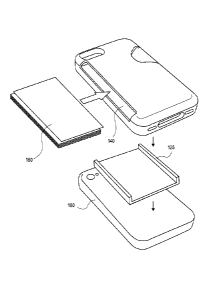
[0033] Figure 2A is a cross-section view of a case 200 for enclosing a
personal
electronic device and a card including exterior hard layer 110, a flexible
inner layer
insert 125, first fitted cavity 150, and second fitted cavity 160. Exterior
hard layer 110 of
case 200 is similar is shape and configuration to the exterior hard layer of
case 100 with
the exception that it may include one or more features for retaining an
inserted personal
electronic device, such as an overhanging portion. Flexible inner layer insert
125 is
inserted into exterior hard layer 110 so as to form the bottom portion of
first fitted cavity
150 and the top and side portions of second fitted cavity 160.
9
CA 02810046 2013-02-28
WO 2012/040306
PCT/US2011/052519
[0034] Figure 2B is a cross-section view of case 200 into which personal
electronic
device 170 is inserted into first fitted cavity 150 and card 180 is inserted
into second
fitted cavity 160
[0035] Figure 2A is an exploded view of case 200 assembly in which card 180
are
inserted into exterior hard layer 110 and flexible inner layer insert 125 is
inserted into
exterior hard layer 110. Personal electronic device 180 is then inserted into
the assembly
of card 180, exterior hard layer 110, and flexible inner layer insert 125.
[0036] Thus, a case for enclosing a personal electronic device and a card has
been herein
described.