Note: Descriptions are shown in the official language in which they were submitted.
CA 02810168 2015-03-18
Description
Title of Invention: POROUS MEMBRANE AND METHOD FOR
MANUFACTURING THE SAME
Technical Field
[0001]
The present invention relates to a polyethylene resin-
based porous membrane and a method for manufacturing the same.
Background Art
[0002]
Recently, with the rapid development of the industry
related to portable electronic devices such as smart phones,
there is a substantially increasing demand for lithium-ion
batteries and lithium polymer batteries, which are
representative secondary batteries. In particular, facing an
age of high oil price, accompanying practical use of electric
vehicles such as hybrid vehicles and plug-in vehicles, it can
be expected that the demand for lithium secondary batteries
will explosively increase in the future. Along with such
industrial demand, there is a demand for reduction in weight
and size and increase in capacity of lithium secondary
batteries as new technical challenges.
[0003]
1
CA 02810168 2015-03-18
Separators, which are main components that influence the
performance of the secondary battery are inserted between
anodes and cathodes, and function to prevent a short-circuit
phenomenon in which the cathodes and the anodes are brought
into contact with each other. Also, in each separator,
infinitely numerous micro pores are formed and through the
pores, ionic substances are transferred between the anode and
the cathode and thereby charged and discharged repeatedly.
[0004]
Such separators each mainly includes a polyolefin resin
that is excellent in chemical stability and electrical
characteristics, and the separators are different in
performance, that is, mechanical strength and electrical
performance, depending on the size, distribution proportion and
orientation structure of the pores that serve as passages of
ionic substances. Accordingly, various techniques for pore
structures of separators have conventionally been developed.
[0005]
For example, Korean Patent No. 373204 (registration date:
February 10, 2003) describes a multicomponent composite
separator for a polyelectrolyte configured so as to include an
active layer at each of surfaces on opposite sides thereof and
a support layer inside thereof, and have a Gurley value of no
more than 20,000 seconds/100 cc.
[0006]
2
CA 02810168 2015-03-18
Also, Korean Patent No. 577731 (registration date: May 1,
2006) describes a microporous separator for a secondary battery
in which a polyolefin resin is used as a main material, an
amorphous layer having a fixed thickness is formed on each of
surfaces on opposite sides thereof, a crystal layer is formed
inside thereof, sizes of pores of the amorphous layer are no
more than 1 m, and sizes of pores of the inside crystal layer
are no more than 5 m and the entire porosity is no less than
50%.
[0007]
Also, Korean Patent No. 776029 (registration date:
November 6, 2007) describes a polyolefin separator for a
secondary battery in which at a cathode-side surface thereof,
the distribution proportion of pores of sizes of 80 nm to 2 m
is 90 to 97% and the distribution proportion of pores of sizes
of less than 80 nm is 3 to 10% and at an anode-side surface
thereof, the distribution proportion of pores of sizes of 30 nm
to 1 m is 90 to 97% and the distribution proportion of pores
of sizes of less than 30 nm is 3 to 10%.
Citation List
Patent Literature
[0008]
Patent Literature 1: Korean Patent No. 577731
Patent Literature 2: Korean Patent No. 776029
3
CA 02810168 2015-03-18
Summary of Invention
Technical Problem
[0009]
However, in a process, of manufacturing a separator such as
described above, a sheet extruded through a T-die is made to
pass between a casting roll and a nip roll in order to cool the
sheet, and at this time, since the casting roll and the nip
roll have radiuses that are different from each other, the
cooling effects of the aforementioned two rolls brought into
contact with the respective surfaces on the opposite sides of
the sheet are not the same.
[0010]
As described above, the conventional separators have the
problem that in the manufacturing process, a minute difference
in cooling speed occurs between the skin layers on the opposite
sides, which makes control of the pore characteristics, that is,
the size and distribution, of the skin layers on the opposite
sides, uneasy. Furthermore, where a raw material resin having
a low molecular weight is used in order to enhance the porosity
of a separator, the ion permeability rises and the electric
performance is thereby enhanced, but the problem of a decrease
in mechanical strength such as tensile strength occurs.
[0011]
4
CA 02810168 2015-03-18
An object of the present invention is to provide a porous
membrane that simultaneously achieves excellent electric
performance and excellent mechanical strength, and has skin
layers on the opposite sides thereof, the skin layers having
same pore characteristics, and a method for manufacturing the
same.
Solution to Problem
[0012]
1. Porous membrane
1.1 First porous membrane
A porous membrane according to the present invention
contains a polyethylene resin having a weight-average molecular
weight of no less than 300,000 and less than 500,000, fibers of
the polyethylene resin being piled up in multiple layers, in
which micro pores are formed so as to extend in a horizontal
direction, and
an average diameter (al) of the micro pores at a
horizontal surface of a core layer is larger than an average
diameter (p1) of the micro pores at a horizontal surface of a
skin layer.
[0013]
In the present invention, a ratio (al) / (31) of the
average diameter (al) to the average diameter (p1) can be no
less than 1.5.
CA 02810168 2015-03-18
[0014]
1.2 Second porous membrane
A porous membrane according to the present invention
contains a polyethylene resin having a weight-average molecular
weight of no less than 300,000 and less than 500,000, fibers of
the polyethylene resin being piled up in multiple layers, in
which micro pores are formed so as to extend in a horizontal
direction, and
an area proportion (a2) of an area occupied by the micro
pores in a horizontal surface of a core layer is larger than an
area proportion (132) of an area of the micro pores in a
horizontal surface of a skin layer.
[0015]
In the present invention, a ratio (a2) / (32) of the area
proportion (a2) to the area proportion (32) can be no less than
1.5.
[0016]
In the aforementioned first and second aspects of the
present invention, it is possible that the porous membrane has
a structure in which the respective micro pores extend in the
horizontal direction and are oriented in multiple layers among
porous base material fibers, and the porous membrane includes
pores of sizes of 0.01 to 0.3 m at a distribution proportion
of 50 to 97% in the entire pores of a skin layer on each of
opposite sides, and pores of sizes of 0.3 to 1 m at a
6
CA 02810168 2015-03-18
distribution proportion of 50 to 97% in the entire pores of the
core layer.
[0017]
In the present invention, the skin layers on the opposite
sides can have a same pore characteristic.
[0018]
In the present invention, ceramic slurry containing an
inorganic filler and an organic binder can be applied to one
surface or both of opposite surfaces of the porous membrane.
[0019]
In the present intention, the ceramic slurry can contain
0.1 to 30% by weight of a water-soluble polymer, 1 to 40% by
weight of a non-water-soluble particulate polymer manufactured
by emulsion polymerization or suspension polymerization, 1 to
50% by weight of the inorganic filler and 20 to 70% by weight
of water.
[0020]
In the present invention, the water-soluble polymer can be
any one or more selected from methylcellulose,
carboxymethylcellulose and salts thereof, and associated
polyurethane and alkali-swellable acrylic resins.
[0021]
In the present invention, the particulate polymer can be
any one or more selected from an acrylic copolymer, a
methacrylic copolymer, a (meth)acrylic-styrene copolymer, a
7
CA 02810168 2015-03-18
(meth)acrylic-acrylonitrile copolymer, a silicon-acrylic
copolymer, an epoxy-acrylic copolymer, polybutadiene,
polyisoprene, a butadiene-styrene random copolymer, an
isoprene-styrene random copolymer, an acrylonitrile-butadiene
copolymer, an acrylonitrile-butadiene-styrene copolymer, a
butadiene-styrene block copolymer and a styrene-butadiene-
styrene-block copolymer.
[0022]
In the present invention, the particulate polymer can have
a particle size of 0.01 to 1 pm.
[0023]
In the present invention, the inorganic filler can be any
one or more selected from CaCO3, A1203, Si02, BaTiO3, Ti02,
Talc, Al(OH)3 and A100H, and having a diameter of 0.1 to 2 pm.
[0024]
2. Porous membrane manufacturing method
A porous membrane manufacturing method according to the
present invention can include:
a process (A) of manufacturing a raw material resin
mixture containing 10 to 90 parts by weight of a solid-type
paraffin oil having a weight-average molecular weight of 100 to
5,000 and 10 to 90 parts by weight of a liquid-type paraffin
oil having a weight-average molecular weight of 300 to 1,500
relative to 100 parts by weight of a polyethylene resin having
8
CA 02810168 2015-03-18
a weight-average molecular weight of no less than 300,000 and
less than 500,000;
a process (B) of extruding and cooling the raw material
resin mixture;
a process (C) of stretching the raw material resin mixture
extruded in the process (B); and
a process (D) of immersing the raw material resin mixture
stretched in the process (C) in an organic solvent to extract
the solid-type paraffin oil and the liquid-type paraffin oil.
[0025]
In the present invention, the porous membrane
manufacturing method can include a process (E) of applying
ceramic slurry including an inorganic filler and an organic
binder to one surface or both of opposite surfaces of the
porous membrane after the process (D). =
[0026]
A porous membrane manufacturing method according to the
present invention can include the steps of:
a) manufacturing a raw material resin mixture containing
to 90 parts by weight of a solid-type paraffin oil having a
weight-average molecular weight of 100 to 5,000, 10 to 90 parts
by weight of a liquid-type paraffin oil having a weight-average
molecular weight of 300 to 1,500 as a pore-forming additive,
and 6 to 10 parts by weight of an antioxidant relative to 100
parts by weight of a polyethylene resin having a melt index of
9
CA 02810168 2015-03-18
0.01 to 0.6 g/10 minutes and a weight-average molecular weight
of no less than 300,000 and less than 500,000;
b) mixing the raw material resin mixture into an extrusion
screw to melt the raw material resin mixture at a temperature
of 180 to 250 C and extrude a gelatinous sheet having a
thickness of 1,000 to 6,000 m, and making the gelatinous sheet
pass between a casting roll and a nip roll, respective surface
temperatures of which are adjusted to 30 to 60 C, to cool the
gelatinous sheet, in which for the nip roll, a nip roll having
a diameter (D1) of a center region thereof that is smaller than
a diameter (D2) of each of end parts on opposite sides of the
nip roll and including a surface having an arc-like inverse
gradient formed in an axial direction is used;
c) sequentially stretching the cooled sheet in a machine
direction and then in a transverse direction by approximately 5
to 15 times, respectively, to manufacture a stretched film
having a thickness of 6 to 50 m; and
d) immersing the stretched film in an extraction solvent
to remove the pore-forming additive, and then thermally fixing
the stretched film at a temperature of 110 to 150 C.
[0027]
In the present invention, an amount of use of the solid-
type paraffin oil and the liquid-type paraffin oil can be 1:
0.8 to 1.2.
[0028]
CA 02810168 2015-03-18
In the present invention, for the nip roll, a nip roll
having a length (L) in the axial direction of 800 to 1,000 mm,
a radius (R) of an arc forming the inverse gradient at the
surface thereof being 500,000 to 2,000,000 mm, can be used.
[0029] =
In the present invention, the raw material resin mixture
can be obtained by mixing the solid-type paraffin oil and the
liquid-type paraffin oil into the polyethylene resin in a state
in which the solid-type paraffin oil and the liquid-type
paraffin oil are previously mixed.
[0030]
A porous membrane manufacturing method according to the
present invention can include the steps of:
A) melting and mixing 10 to 90 parts by weight of a solid-
type paraffin wax having a weight-average molecular weight of
100 to 5,000 and 10 to 90 parts by weight of a liquid-type
paraffin oil having a weight-average molecular weight of 300 to
1,500 at a temperature of 80 to 100 C to manufacture a paraffin
wax mixture;
B) putting the paraffin wax mixture in a high-temperature
state into an extrusion screw together with 100 parts by weight
of a polyethylene resin having a weight-average molecular
weight of no less than 300,000 and less than 500,000 to be
melted and kneaded at a t mperature of 180 to 250 C, and then
extruding and cooling the resulting mixture to manufacture a
11
CA 02810168 2015-03-18
gelatinous sheet, and biaxially stretching the gelatinous sheet
and then immersing the gelatinous sheet in an organic solvent
to manufacture a porous base material;
C) mixing 0.1 to 30% by weight of a water-soluble polymer
and 1 to 40% by weight of a non-water-soluble particulate
polymer manufactured by emulsion polymerization or suspension
polymerization, 1 to 50% by weight of an inorganic filler and
20 to 70% by weight of water to manufacture aqueous-dispersion
ceramic slurry; and
D) applying the aqueous-dispersion ceramic slurry to one
surface or both of opposite surfaces of the porous base
material in a thickness of 1 to 5 m to form a ceramic coating
layer.
[0031]
In the present invention, in order to cool the gelatinous
sheet in the B) step, the gelatinous sheet is made to pass
between a casting roll and a nip roll, respective surface
temperatures of which are adjusted to 30 to 60 C, and a roll
including an inverse gradient formed at an outer surface of the
nip roll, a radius of a circle circumscribing the outer surface
in a length direction is 500,000 to 2,000,000 mm, can be used.
[0032]
In the present invention, the ceramic-coated porous
membrane can have a thickness of 10 to 30 m, a porosity of 30
to 50%, a Gurley value of 100 to 400 sec/100 ml, a tensile
12
CA 02810168 2015-03-18
strength of 1,000 to 3,000 kgf/cm2, and a thermal contractility
of less than 5% in each of a machine direction and a transverse
direction upon exposure at 150 C for one hour.
Advantageous Effects of Invention
[0033]
Compared to conventional porous membranes, a porous
membrane according to the present invention has the
characteristics of high mechanical strength as well as low
electrical resistance and having excellent electric performance
under same conditions.
[0034]
Accordingly, such porous membrane can be expected to
largely contribute to reduction in weight and size and increase
in capacity of secondary batteries such as lithium-ion
batteries and lithium polymer batteries.
[0035]
Furthermore, use of both solid-type paraffin oil and
liquid-type paraffin oil enables the stretch ratio to be
increased, and as a result, reduction in thickness can be
achieved while the excellent strength is achieved.
[0036]
In a ceramic-coated porous membrane according to the
present invention, a ceramic coating layer has been applied to
a porous base material of polyethylene, whereby excellent
13
CA 02810168 2015-03-18
physical strength and excellent thermal stability are achieved,
and in particular, the porous base material has a cross-
sectional structure in which pores are oriented in multiple
layers in skin layers and a core layer thereof, providing the
effect of almost no phenomenon of a decrease in air
permeability due to the ceramic coating layer occurring.
[0037]
Accordingly, a ceramic-coated separator having a further
decreased thickness compared to those of conventional porous
membranes under same conditions can be manufactured, and thus,
can contribute to capacity increase, size reduction and output
increase of future secondary batteries, and furthermore, is
expected to be widely used also for middle or large-size
secondary batteries such as electric vehicles and fuel
batterieS.
[0038]
Also, aqueous-dispersion ceramic slurry used in the
present invention uses water as a dispersion medium without
using volatile organic substances harmful to human bodies and
thus, generates no environmental pollutants in the application
and dry process, providing the effects of provision of an
environment-friendly working surroundings and no possibility of
damage of workers' health.
Brief Description of Drawings
14
CA 02810168 2015-03-18
[0039]
[Figure 1] Figure 1 is a scanning electron microscope
photograph taken of a state of a cross-section of a porous
membrane according to the present invention.
[Figure 2] Figure 2 is scanning electron microscope photographs
taken of states of surfaces of skin layers (A and C) on
opposite sides and a core layer (B) of a porous membrane
according to an example of the present invention.
[Figure 3] Figure 3 is scanning electron microscope photographs
of states of surfaces of skin layers (A and C) on opposite
sides and a core layer (B) of a porous membrane according to
another example of the present invention.
[Figure 4] Figure 4 is scanning electron microscope photographs
of states of surfaces of skin layers (A and C), on opposite
sides and a core layer (B) of a porous membrane according to
another example of the present invention.
[Figure 5] Figure 5 is scanning electron microscope photographs
of states of surfaces of skin layers (A and C) on opposite
sides and a core layer (B) of a porous membrane according to
another example of the present invention.
[Figure 6] Figure 6 is a diagram illustrating a structure of a
nip roll used to cool a gelatinous sheet.
[Figure 7] Figure 7 is a scanning electron microscope
photograph taken of a cross-sectional structure of a ceramic-
CA 02810168 2015-03-18
coated porous membrane according to the present invention at a
magnification of 5500 times.
Description of Embodiments
[0040]
The present invention will be described in detail below.
However, the terms used to describe the present invention can
be used as concepts specifically defined for the object of the
present invention.
[0041]
In the present embodiments, a porous membrane will be
described taking a porous separator as an example.
[0042]
1. First Embodiment
An example in which a porous membrane according to the
present invention is employed as a porous membrane will be
described. The porous membrane includes a polyethylene resin
having a weight-average molecular weight of no less than
300,000 and less than 500,000. In this case, if a polyethylene
resin having a weight-average molecular weight of less than
300,000 is used, the stretchablility of the porous membrane is
enhanced, but the problem of a decrease in mechanical strength
occurs, and meanwhile, if a polyethylene resin having a weight-
average molecular weight of no less than 500,000 is used, the
mechanical strength of the porous membrane is enhanced, but the
16
CA 02810168 2015-03-18
problems of a decrease in stretchability and kneadability,
resulting in a decrease in productivity, and uneasiness of
control of the sizes of pores occur.
[0043]
For reference, conventional separators for secondary
batteries mainly use a polyolefin resin having a weight-average
molecular weight of no less than 500,000, desirably no less
than 1,000,000 in order to maintain a desirable mechanical
strength although the productivity and the pore characteristics
are poor.
[0044]
The porous membrane is configured so that fibers of a
polyethylene resin are piled up in multiple layers, micro pores
are formed so as to extend in a horizontal direction, and an
average diameter in the horizontal direction of the micro pores
is larger in a center portion than in surface portions. More
specifically, the porous membrane has a structure in which
respective micro pores grew in the horizontal direction and
oriented in multiple layers among fibers of a porous base
material, and the porous membrane includes pores of sizes of
0.01 to 0.3 m at a distribution proportion of 50 to 97% in the
entire pores of a skin layer on each of opposite sides, and
pores of sizes of 0.3 to 1 m exist at a distribution
proportion of 50 to 97% in the entire pores of a core layer.
The porous membrane has a cross-sectional structure in which
17
CA 02810168 2015-03-18
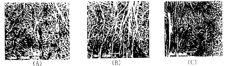
micro pores are oriented in multiple layers. The attached
Figure 1 is a scanning electron microscope (SEM) photograph
taken of a state of a cross-section of a porous membrane
according to an example of the present invention at a
magnification of 20,000 times: it can be confirmed with naked
eyes that micro fiber tissues are arranged side by side in the
transverse direction of Figure 1, and between the micro fiber
tissues, numerous micro pores are oriented in layers, and in
particular, pores arranged in the core layer (the intermediate
region in Figure 1) of the porous membrane are larger compared
to pores arranged in the skin layers (the upper and lower end
regions in Figure 1) on the opposite sides of the porous
membrane.
[0045]
An average diameter (al) of the micro pores at a
horizontal surface of the core layer is larger than an average
diameter (p1) of the micro pores at a horizontal surface of
each of the skin layers, and more specifically, a ratio (al) /
(f31) of the average diameter (al) to the average diameter (f31)
= is no less than 1.5, preferably no less than 2.0, more
preferably 2.0 to 5Ø
[0046]
An area proportion (a2) of an area occupied by the micro
pores in a horizontal surface of the core layer is larger than
an area proportion (132) of an area of the micro pores in a
18
CA 02810168 2015-03-18
horizontal surface of each of the skin layers, and the ratio
(a2) / (f32) of the area proportion (a2) to the area proportion
(32) is no less than 1.5, preferably no less than 2.0, more
preferably 2.0 to 10Ø
[0047]
As a result of the porous membrane having the
aforementioned structure of the pores oriented in the multiple
layers, an excellent mechanical strength can be maintained
while a polyethylene resin having a weight-average molecular
weight that is much smaller than those of conventional
separators is used, and open cells, which are directly related
to air permeability, are formed at a high proportion. Here,
the open cells refer to respective micro pores mutually
connected in a direction of the thickness of the porous
membrane, and through the respective open cells, ionic
substances smoothly move between an anode and a cathode.
[0048]
Meanwhile, Figures 2 to 5 include OEM photographs taken of
each of skin layers on opposite sides and a core layer of a
porous membrane manufactured according to an example of the
present invention at a magnification of 20,000 times. The left
photographs A are photographs each taken of a state of an upper
surface of the respective porous membranes, and the right
photographs C are photographs each taken of a state of a lower
surface of the respective porous membranes, and the center
19
. .
CA 02810168 2015-03-18
photographs B are photographs each taken of a state of a core
layer by peeling a skin layer from the porous membrane.
[0049]
It can be seen from Figures 2 to 5 that small-size pores
are distributed in the skin layers on the opposite sides of the
porous membrane (photographs A and C) and relatively large
pores are distributed in the core layer of the porous membrane
(photograph B). As a result of taking a plurality of SEM
photographs of a porous membrane according the present
invention by a method that is the same as above, measuring the
sizes of pores distributed in each of the skin layers and the
core layer and calculating the respective degrees of
distribution, it was confirmed that a distribution proportion
of the pores of sizes of 0.01 to 0.3 m in the skin layers on
the opposite sides is 50 to 97%, a distribution of pores of
sizes of 0.3 to 1 m in the core layer is 50 to 97%, and the
skin layers on the opposite sides have the same sizes and
distribution of pores.
[0050]
Based on the aforementioned SEM photographs, it was
confirmed that an average diameter (a1) of the micro pores at
a horizontal surface of the core layer is larger than an
average diameter (Jill) of the micro pores at a horizontal
surface of each of the skin layers, and more specifically, a
ratio (al) / (p1) of the average diameter (al) to the average
CA 02810168 2015-03-18
diameter (131) is no less than 1.5. Also, it was confirmed that
an area proportion (u2) of an area occupied by the micro pores
in the horizontal surface of the core layer is larger than an
area proportion (132) of an area of the micro pores in the
horizontal surface of each of the skin layers, and the ratio
(c2) / (132) of the area proportion (a2) to the area proportion
(P2) is no less than 1.5.
[0051]
Furthermore, it can be seen in the core layer of the
porous membrane (photographs B), thick fiber bundles like leaf
veins or strings are distributed, and it can be considered that
the respective fiber bundles enlarge the sizes of the pores
distributed in the core layer, enabling an excellent mechanical
strength to be maintained while using a polyethylene resin
having a weight-average molecular weight that is much smaller
than those of conventional separators.
[0052]
As a result of taking a plurality of scanning electron
microscope (SEM) photographs of a state of a cross-section of a
porous base material according to the present invention as in
Figures 1 and 2, measuring actual sizes of pores distributed in
each of skin layers and a core layer thereof and then
determining a distribution chart thereof, it was confirmed that
a distribution proportion of pores of sizes of 0.01 to 0.3 m
in each of the skin layers on the opposite sides is 50 to 97%,
21
CA 02810168 2015-03-18
a distribution proportion of pores of sizes of 0.3 to 1 m in
the core layer is 50 to 97% and the skin layers on the opposite
sides have the same sizes and distribution of pores.
[0053]
Hereinafter, a method for manufacturing a porous membrane
according to the present invention includes the processes of:
A) of manufacturing a raw material resin mixture containing 10
to 90 parts by weight of a solid-type paraffin oil having a
weight-average molecular weight of 100 to 5,000, preferably 100
to 1,000, and 10 to 90 parts by weight of a liquid-type
paraffin oil having a weight-average molecular weight of 300 to
1,500, preferably 900 to 1,500, relative to 100 parts by weight
of a polyethylene resin having a weight-average molecular
weight of no less than 300,000 and less than 500,000; B)
melting and extruding the raw material resin mixture; C)
stretching the raw material resin mixture extruded in the (B)
process; and D) immersing the raw material resin mixture
stretched in the (C) process in an organic solvent to extract
the solid-type paraffin oil and the liquid-type paraffin oil.
Hereinafter, the respective processes will be described in
detail.
[0054]
A) Raw material resin mixture mixing process
First, a raw material resin mixture containing, 10 to 90
parts by weight of a solid-type paraffin oil having a weight-
22
CA 02810168 2015-03-18
average molecular weight of 100 to 5,000 as a pore-forming
additive, a 10 to 90 parts by weight of a liquid-type paraffin
oil having a weight-average molecular weight of 300 to 1,500,
and 6 to 10 parts by weight of an antioxidant in 100 parts by
weight of a polyethylene resin having a melt index of 0.01 to
0.6g/10 minutes and a weight-average molecular weight of no
less than 300,000 and less than 500,000 is manufactured.
[0055]
More specifically, the raw material resin mixture is
manufactured as follows.
[0056]
A paraffin wax mixture is manufactured in advance by
mixing and melting 10 to 90 parts by weight of a solid-type
paraffin wax having a weight-average molecular weight of 100 to
5,000, preferably 100 to 1,000, and 10 to 90 parts by weight of
a liquid-type paraffin oil having a weight-average molecular
weight of 300 to 1500, preferably, 900 to 1,500, at a
temperature of 80 to 100 C.
[0057]
In other words, for the raw material resin mixture, first,
a solid-type paraffin oil is heated and melt, and a liquid-type
paraffin oil is mixed into the solid-type paraffin oil to
manufacture a pore-forming additive. Consequently, the pore-
forming additive is maintained in a gelatinous state, and it is
desirable that such pore-forming additive in a gelatinous state
23
CA 02810168 2015-03-18
be mixed to a polyethylene resin and an antioxidant. The
mixture of the solid-type paraffin wax and the liquid-type
paraffin oil is subsequently melt and kneaded and processed as
a pore-forming additive together with the polyethylene resin
and the processing additive, whereby the mixture functions to
form a pore structure in which pores are oriented in multiple
layers inside the porous base material afterward. As described
above, use of a solid-type paraffin wax and a liquid-type
paraffin oil together as a pore-forming additive enables a
large increase in stretch ratio of subsequent sequential
stretching of the resulting gelatinous sheet, as the stretch
ratio is higher, the orientation and crystallization degrees of
the molecules are raised, and thus, the physical strength of
the porous base material is increased. Accordingly, the
tensile strength and the puncture strength of the porous base
material can be enhanced and furthermore, reduction in
thickness of the porous membrane can be achieved.
[0058]
Next, the mixture of the solid-type paraffin wax and the
liquid-type paraffin oil, and a polyethylene resin and an
antioxidant are mixed to manufacture a raw material resin
mixture.
[0059]
At this time, use of a polyethylene resin having a melt
index of less than 0.01 g/10 minutes results in poor mixture
24
CA 02810168 2015-03-18
with the pore-forming additive because of the low fluidity of
the polyethylene resin, causing the problem of difficulty to
obtain a sheet having a uniform thickness in a stretching
process. Meanwhile, use of a polyethylene resin having a melt
index of no less than 0.6 g/10 minutes may result in the resin
running down in the sheet extrusion step because of the very
high fluidity of the resin, causing the problem of a decrease
in mechanical strength of the finished porous membrane.
[0060]
Also, in the pore-forming additive, a ratio between the
solid-type paraffin oil and the liquid-type paraffin oil may be
a ratio of 1:0.8 to 1.2, desirably 1:1. If the amount of use
of the solid-type paraffin oil and the amount of use of the
liquid-type paraffin oil are each less than 10 parts by weight,
the porosity of the porous membrane is decreased, which may
result in poor charging performance of the resulting secondary
battery, and meanwhile, if the amount of use of the solid-type
paraffin oil and the amount of use of the liquid-type paraffin
oil are each no less than 90 parts by weight, phase separation
occurs between the polyethylene resin and the pore-forming
additive during the sheet extrusion process, which may result
in occurrence of breakage of the sheet.
[0061]
For the paraffin oils, it is desirable to use waxes. The
solid-type paraffin oil can be obtained by wax extracted and
CA 02810168 2015-03-18
separated from an oil such as, in particular, light oil being
subjected to solvent deoiling, chemical treatment and clay
treatment. The liquid-type paraffin oil can be obtained by a
liquid oil extracted and separated from an oil such as light
oil being subjected to refining, dewatering and deodorization.
[0062]
For the antioxidant, an ordinary antioxidant can be used,
and in particular, a phosphate additive, for example, phosphite
ester can be used.
[0063]
In the present invention, various types of additives such
as ultraviolet absorbers, antiblocking agents, pigments,
colorants and inorganic fillers other than the antioxidant can
be added as necessary.
[0064]
B) Raw material resin mixture extrusion and cooling
process
Next, the raw material resin mixture is mixed into an
extrusion screw, and melt at a temperature of 180 to 250 C and
sufficiently mixed, and the raw material resin mixture is then
extruded through a T-die to manufacture a gelatinous sheet
having a thickness of 1,000 to 6,000
[0065]
Subsequently, the gelatinous sheet is made to pass between
a casting roll and a nip roll, respective, surface temperatures
26
CA 02810168 2015-03-18
of which are adjusted to 30 to 60 C. Consequently, skin layers
of the sheet that is brought into direct-contact with the
casting roll and the nip roll are cooled and solidified
relatively early, and a core layer of the sheet is cooled and
solidified slowly compared to the skin layers of the sheet. At
this time, in the skin layers where the pore-forming additive
is cooled and solidified early together with the polyethylene
resin, particles each having a relatively-small volume are
formed, and in the core layer where the pore-forming additive
is gradually cooled, particles each having a relatively-large
volume are formed.
[0066]
The casting roll may be made to have a radius that is
around 1.4 to 1.6 times larger than the nip roll. In such case,
when the gelatinous sheet is made to pass between the casting
roll and the nip roll, the nip roll rotates considerably faster
compared to the casting roll, and thus, the two rolls have
different sheet cooling capabilities, and accordingly, the
problem that the pore structures formed in the skin layers on
the opposite side of the sheet are different from each other
occurs.
[0067]
In order to solve such problem, a nip roll with the
"inverse gradient" formed in an axial direction thereof is used.
Here, "inverse gradient" refers to a shape in which a diameter
27
CA 02810168 2015-03-18
(D1) of a center region of the nip roll is smaller than a
diameter (D2) of each of opposite end parts of a nip roll,
whereby an outline of the nip roll has an arc shape as
illustrated in Figure 6. Here, it is desirable that the nip
roll have a length (L) in the axial direction of 800 to 1,000
mm, and the arc forming the inverse gradient, that is, a radius
(R) of a circle circumscribing the nip roll in the axial
direction (radius of a circle circumscribing an outer surface
of the nip roll in a length direction) be 500,000 to 2,000,000
mm. For reference, in Figure 6, for ease of understanding, the
radius (R) of the arc is indicated so as to be relatively
smaller compared to the length (L) of the nip roll; however, it
should be understood that the radius (R) is much larger in
reality.
[0068]
As described above, where an inverse gradient is formed at
the surface of the nip roll, the surface area of the nip roll
is increased by that amount, and thus, even if the nip roll has
a high rotation speed compared to that of the casting roll, the
nip roll has a cooling capability that is the same as that of
the casting roll. If the radius (R) of the arc forming the
inverse gradient is less than 500,000 mm, the difference
between the diameter (D1) of the center region and the diameter
(D2) of each of the opposite end portions is too large, causing
the problem of an excessively large difference in thickness
28
CA 02810168 2015-03-18
between the center region and each of the opposite end part of
the sheet, and if the radius (R) is no less than 2,000,000 mm,
the problem of insufficiency in cooling effect, of the nip roll
occurs.
[0069]
Meanwhile, if the surface temperatures of the casting roll
and the nip roll are less than 30 C, the pore-forming additive
sticks to the roll surfaces while being rapidly cooled,
resulting in occurrence of irregularities of the surfaces of
the gelatinous sheet or a failure to obtain a sheet having a
uniform thickness. Conversely, if the surface temperatures are
no less than 60 C, the pore-forming additive is not solidified,
making formation of pores difficult, and the liquid-type
paraffin oil adheres to the casting roll surface, causing
slippage between the sheet and the rolls, resulting in
occurrence of the problem of a failure to stretch the sheet at
a predetermined ratio.
[0070]
C) Sheet stretching process
Next, the cooled sheet is sequentially stretched in a
machine direction and then in a transverse direction by
approximately 5 to 15 times, respectively, to manufacture a
film having a thickness of 6 to 50 m. In other words, the
sheet is first stretched in the machine direction by 5 to 15
times, and then stretched again in the transverse direction by
29
CA 02810168 2015-03-18
to 15 times. Consequently, the difference in thickness
occurring due to the inverse gradient of the nip roll is
eliminated, making the film has an entirely-uniform thickness
distribution as well as having a multilayer orientation
structure in which the respective pore-forming additives
distributed in the skin layers and the core layer are arranged
in layers.
[0071]
In general, during manufacture of a porous membrane,
uniaxial stretching in which the membrane is stretched in only
one of a machine direction and a transverse direction is
performed or simultaneous biaxial stretching in which the
membrane is stretched in both of the directions simultaneously.
However, in the case of the uniaxial stretching, a sheet must
be stretched only in a direction in which the machine ejects
the sheet, that is, only in a machine direction, resulting in a
decrease in productivity. Meanwhile, in the case of
simultaneous biaxial stretching, the stretching force imposed
on the sheet is reduced, and thus, there is the problem of
difficulty in high-speed and wide stretching.
[0072]
However, in the present embodiment, sequential biaxial
stretching in which stretching is performed in a machine
direction and then in a transverse direction, providing
excellent productivity and enabling stretching at a high-
CA 02810168 2015-03-18
stretch ratio, and the resulting porous membrane includes micro
pores formed in a multilayered structure inside thereof, and
thereby has an excellent mechanical strength.
[0073]
D) Pore-forming additive extraction process
Lastly, the stretched sheet is immersed in an extraction
solvent to remove the pore-forming additive, thereby micro
pores being formed, and is thermally-fixed in a thermal
fixation chamber at 110 to 150 C to remove residual stress. At
this time, examples of usable organic solvents include, e.g.,
hydrocarbons such as pentane, hexane, heptane, chlorinated
hydrocarbons such as methylene chloride and carbon
tetrachloride, fluorohydrocarbons, and ethers such as diethyl
ether and dioxane.
[0074]
If the thermal fixation temperature is less than 110 C,
the problem of a decrease in thermal resistance of the porous
membrane occurs, and meanwhile, if the thermal fixation
temperature is no less than 150 C, problems such as breakage of
the porous membrane may occur.
[0075]
A porous membrane according to the present embodiment can
be widely utilized as a separator for an electronic component
such as a lithium-ion capacitor or a lithium-ion cover sheet
other than a separator for a secondary battery.
31
CA 02810168 2015-03-18
[0076]
2. Second embodiment
A porous membrane according to a second embodiment is one
obtained by applying aqueous dispersion-type ceramic slurry to
a porous membrane according to the first embodiment. The
aqueous dispersion-type ceramic slurry according to the present
embodiment includes 0.1 to 30% by weight of a water-soluble
polymer, 1 to 40% by weight of a non-water-soluble particulate
polymer, 1 to 50% by weight of an inorganic filler and 20 to
70% by weight of water. In the ceramic slurry, a part of the
water-soluble polymer used as an organic binder adsorbs onto a
surface of the inorganic filler, and a remaining part of the
same exists in such a manner that the remaining part is
dispersed in the water, whereby all of the components including
the inorganic filler are stably maintained in an emulsion state.
[0077]
Accordingly, if the content of the water-soluble polymer
is less than 0.1% by weight, the amount of the water-solUble
polymer adsorbing onto the surface of the inorganic filler
decreases, making the maintenance of the entire uniform
dispensability difficult, which may result in a failure to form
a uniform ceramic coating layer. Meanwhile, if the content of
the water-soluble polymer exceeds 30% by weight, the velocity
of the aqueous-dispersion ceramic slurry becomes too high,
which may result in the respective particles of the inorganic
32
CA 02810168 2015-03-18
filler adsorbing onto one another, causing cross-linking
aggregation, and in such case, the smoothness of the coating
surface of the coating layer is lowered, making it difficult to
obtain a uniform ceramic coating layer.
[0078]
For the water-soluble polymer, one or more selected from
methylcellulose, carboxymethylcellulose and salts thereof can
be used as an ionic cellulose semisynthetic polymer, and one or
more selected from associated polyurethane and alkali-swellable
acrylic resins can be used as a synthetic polymer.
[0079]
Next, the non-water-soluble particulate polymer is
manufactured by emulsion polymerization or suspension
polymerization as an organic binder in which a particulate
polymer containing one or more hydrophilic groups selected from
a group of a carboxyl group, a hydroxyl group and a sulfonate
group is uniformly dispersed in water. As a result of
containing the hydrophilic group(s), the particulate polymer
has a function that enhances the dispersion stability of the
inorganic filler and the bonding of the coating layer to the
inorganic filler and a porous base material.
[0080]
In the present embodiment, if the content of the non-
water-soluble particulate polymer is less than 1% by weight,
the particulate polymer cannot effectively exert the
33
CA 02810168 2015-03-18
aforementioned function, and meanwhile, if the content of the
non-water-soluble particulate polymer exceeds 40% by weight,
the porousness of the ceramic coating layer is decreased and
the performance of the secondary battery may be thereby
decreased. For the particulate polymer, one or more selected
from an acrylic copolymer, a methacrylic copolymer, a
(meth)acrylic-styrene copolymer, a (meth)acrylic-acrylonitrile
copolymer, a silicon-acrylic copolymer, an epoxy-acrylic
copolymer, polybutadiene, polyisoprene, a butadiene-styrene
random copolymer, an isoprene-styrene random copolymer, an
acrylonitrile-butadiene copolymer, an acrylonitrile-butadiene-
styrene copolymer, a butadiene-styrene block copolymer and a
styrene-butadiene-styrene-block copolymer can be used.
[0081]
It is desirable that the particulate polymer have a
particle size of 0.01 to 1.0 m. If the particle size is no
more than 0.01 m, the porousness is lowered and the resistance
of the ceramic coating layer is increased, which may result in
a decrease in performance of the battery, and meanwhile, if the
particle size is no less than 1.0 m, the number of contact
points between the particulate polymer and the inorganic filler
is decreased, causing the problem of a decrease in bonding
force between the respective particles of the inorganic filler
or between the inorganic filler and the coating layer.
[0082]
34
CA 02810168 2015-03-18
Next, the inorganic filler functions to improve the
thermal stability of the ceramic-coated porous membrane, and if
the content thereof is less than 1% by weight, no effective
thermal stability can be expected, and meanwhile, if the
content thereof is no less than 50% by weight, precipitation of
the inorganic filler may occur inside the ceramic slurry,
making it difficult to obtain not only sufficient dispersion
stability but also a uniform coating layer upon application.
Here, the inorganic filler suppresses aggregation of inorganic
particles to optimize the fluidity of the ceramic slurry, and
thus, it is desirable that a measured value of the BET specific
surface area be 1.5 to 150 m2/g and it is desirable that the
particle diameter (volume-average D50 average particle
diameter) be 0.1 to 2 m. Here, if the particle diameter of
the inorganic fillers is less than 0.1 m, no coating layer
having uniform distribution can be formed because of poor
dispersibility, and meanwhile, if the particle diameter exceeds
2 m, short-circuiting of the battery may be induced because of
excessively good air permeability.
[0083]
For the inorganic filler, one or more selected from CaCO3,
A1203, Si02, BaTiO3, Ti02, Talc, Al(OH)3 and AlOOH can be used,
and for such inorganic filler, it is important that the
dispersion stability is excellent and when the ceramic slurry
is prepared, no sedimentation occurs and a uniform slurry state
CA 02810168 2015-03-18
can be maintained over a long period of time. As a result of
the present inventors testing various kinds of inorganic
substances, aluminum oxide (A1203) from among the
aforementioned inorganic fillers exhibited an optimum result
for achieving the object of the present invention.
[0084]
Next, the water functions as a dispersion medium that
allows uniform dispersion of the water-soluble polymer and the
non-water-soluble particulate polymer and the inorganic filler,
and if the content of the water is less than 20% by weight, no
sufficient aqueous dispersion of the respective components can
be performed, making the application work difficult, causing
the problem of a failure to form a uniform coating layer.
Meanwhile, the content of the water is no less than 70% by
weight, a problem may occur in the drying process after
application of the ceramic slurry.
[0085]
The ceramic slurry according to the present embodiment can
contain any additive such as a dispersant, a viscosity modifier,
a leveling agent, an antioxidant, a bonding agent, an additive
having a function such as electrolyte decomposition suppression,
as necessary, in addition to the water-soluble polymer and the
non-water-soluble particulate polymer, and the inorganic filler
and the water.
[0086]
36
CA 02810168 2015-03-18
Meanwhile, a method for manufacturing a microporous
ceramic-coated porous membrane according to the present
embodiment includes a process of manufacturing a porous base
material, a process of manufacturing aqueous-dispersion ceramic
slurry, and a process of forming a ceramic coating layer. For
the process of manufacturing a porous base material, the
manufacturing process described in the first embodiment can be
employed.
[0087]
Since for the process of manufacturing a porous base
material, the process described in the first embodiment can be
employed, a detailed description thereof will be omitted.
[0088]
In the process of manufacturing aqueous-dispersion ceramic
slurry, respective components, that is, 0.1 to 30% by weight of
a water-soluble polymer, 1 to 40% by weight of a non-water-
soluble particulate polymer, 1 to 50% by weight of an inorganic
filler and 20 to 70% by weight of water and an adequate amount
of another additive added as necessary are mixed, for example,
sufficiently mixed at 40 C for around 12 hours using ball
milling to manufacture aqueous-dispersion ceramic slurry.
[0089]
Lastly, for a method for applying the ceramic slurry to a
porous base material to form a ceramic coating layer thereon,
an ordinary application method can be used. For example, any
37
CA 02810168 2015-03-18
of various methods such as dip coating, die coating, gravure
coating, comma coating and a method of combination of any of
these can be used. From among these, in order to obtain a
uniformly-coated surface, dip coating or gravure coating is
desirable. Also, examples- of a dying method after the
application can include drying using warm air, hot air and low-
humidity air, vacuum drying or drying using irradiation with,
e.g., far-infrared ray or electron ray, but hot-drying in a
temperature range of 80 to 120 C is desirable.
[0090]
It is desirable that the ceramic coating layer have a
thickness of 1 to 5 gm. If the thickness is less than 1 gm,
the problem of a large increase in thermal contractility of the
porous membrane occurs, and if the thickness exceeds 5 gm, the
porous membrane becomes too thick, causing problems in
assembling of the lithium secondary battery or difficulty in
downsizing of the battery. Furthermore, the ceramic coating
layer can be applied to only one surface of the porous thin-
membrane base material or can also be applied both of opposite
surfaces thereof; however, double-side coating is more
effective for enhancement of the thermal stability of the
porous membrane than one-side coating.
[0091]
According to the present embodiment, at the time of a
drying step conducted after application of ceramic slurry, in
38
CA 02810168 2015-03-18
the drying process, phase separation occurs between water,
which is a dispersion medium, and other components and
simultaneously, the inorganic filler, the water-soluble polymer
and the particulate polymer are bound to one another to form
nanosized aggregates. In the ceramic coating layer according
to the present embodiment, micro voids are formed among the
respective aggregates, and a microporous structure is formed
while the water is vaporized and dried through the micro voids,
and in particular, a proportion of open cells is increased,
enabling provision of excellent air permeability.
[0092]
On the other hand, in the case of a ceramic coating layer
using conventional organic/inorganic coating solutions, pores
are formed in the drying process using phase inversion of
solvent/non-solvent, for example, acetone/moisture. However,
in such pore formation mechanism using phase inversion,
adjustment of the sizes of the pores is difficult, and even if
pores are formed, the inner passages are often occluded, and
thus, it is difficult to provide smooth air permeation.
[0093]
A microporous ceramic porous membrane according to the
present invention, which is manufactured by the aforementioned
method, has a thickness of 10 to 30 m, and a porosity of 30 to
50%, an air permeability of 100 to 400 sec/100 ml, a tensile
strength of 1,000 to 3,000 kgf/cm2, and a thermal contractility
39
CA 02810168 2015-03-18
of less than 5% in each of a machine direction and a transverse
direction upon exposure at 150 C for one hour.
[0094]
The microporous ceramic porous membrane can be employed
for, for example, a portable secondary battery for, e.g., a-
mobile phone or a laptop personal computer, a large-volume
secondary battery for an electric automobile, a super secondary
battery, and a lithium-ion capacitor.
[0095]
Operation and effects of the second embodiment will be
described below.
[0096]
Widely-used conventional polyolefin porous membranes are
poor in thermal stability for high temperature and physical
strength, and when such a conventional polyolefin porous
membrane is subjected to exposure at a temperature of 150 C for
around one hour, the polyolefin porous membrane exhibits a
thermal contractility of 50 to 90%, and thereby loses the
function of the separator, and such a polyolefin porous
membrane also has the problem that internal short-circuiting is
highly likely to occur upon receipt of an impact from the
outside. A technique generally employed recently to cover such
shortcomings is ceramic coating.
[0097]
CA 02810168 2015-03-18
For example, Korean Patent Registration No. 739337
(2007.07.06), Korean Patent No. 754746 (2007.08.27), Korean
Patent No. 858214 (2008.09.04), Korean Patent Laid-Open No.
2010-28009 (2010.03.11) and Korean Patent Laid-Open No. 2011-
35847 (2011.04.06) each propose an organic/inorganic composite
ceramic-coated separator obtained by applying a coating
solution including inorganic particles and a polymer binder to
at least one surface of a polyolefin porous base material to
form a porous active layer. Each of the ceramic-coated
separators described in the aforementioned related patents
reportedly has a remarkably-improved thermal stability compared
to ordinary separators including no ceramic coating layer.
However, there are considerable technical problems remained in
such conventional ceramic-coated separators with regard to air
permeability, which is an extremely important factor for the
performance of the separators.
[0098]
In other words, in general, when a ceramic coating layer
is applied to a surface of a porous base material, the thermal
stability of the separator is enhanced, but the coating layer
blocks pores formed in the porous base material, resulting in a
decrease in air permeabilty of the separator, and in such case,
ion transfer passages between an anode and a cathode are
largely reduced, causing the problem of a large decrease in
charging and discharging performance of the secondary battery.
41
CA 02810168 2015-03-18
[0099]
Seeing Korean Patent Registration No. 1029672 (2011.04.08)
for reference, it is reported that while a numerical value
indicating a Gurley value of a polyethylene separator including
no ceramic coating layer is approximately 230 sec/100 ml, when
a coating layer is applied to a surface thereof, the numerical
value is increased to 380 to 415 sec/100 ml, which indicates a
large decrease in air permeability. Also, Korean Patent
Registration No. 971109 (2010.07.13) reports that although a
polyethylene separator including no coating layer has air
permeability of around 322 sec/100 ml, after completion of
double-side application, the necessary airflow time is
increased to 420 to 470 sec/100 ml under same conditions. As
described above, an increase in time indicating the Gurley
value means that the air permeability is reduced, and such
result means that the ceramic coating layer blocks the pores in
the porous base material. Accordingly, there is a need for
development of a porous coating separator whose air
permeability is not decreased even after application of a
ceramic coating layer.
[0100]
Although a majority of organic/inorganic-composite coating
solutions used in the conventional ceramic coating techniques
use volatile organic substances (VOC) such as toluene,
methylene chloride, chloroform, ethanol, acetone and N-methyl-
42
CA 02810168 2015-03-18
2-pyrrolidone (NMP) as solvents, such volatile organic
substances are well known to be extremely harmful to human
bodies or recognized as environmental pollutants, and in
particular, have the problem of adversely affecting the health
of workers during the application and drying process.
[0101]
Meanwhile, in the secondary battery product market, an
increase in output and a decrease in manufacturing cost of
batteries are big issues. In order to respond to such demands
in the market, it is necessary to develop a porous membrane
with a thickness smaller than those of existing porous films
and a heat resistance and physical properties improved compared
to those of the existing porous membranes.
[0102]
According to the present embodiment, a microporous
ceramic-coated porous membrane with excellent thermal stability
and physical strength, a small thickness and providing almost
no adverse effect of reduction in air permeability due to a
ceramic coating layer can be provided.
[0103]
Also, according to the present embodiment, a microporous
ceramic-coated porous membrane that has no possibility of
discharging environmental pollutants during the manufacturing
process and also provides an environment-friendly work space
and has no harm to the health of workers can be manufactured.
43
CA 02810168 2015-03-18
Examples of the present invention will be described below.
However, the scope of right for the present invention is not
limited by these Examples.
Example 1
[0104]
1. Examples of first porous membrane
(Example 1-1)
A pore-forming additive was manufactured by mixing 9.9 kg
of a solid-type wax having a weight-average molecular weight of
3746 and 9.9 kg of a liquid-type wax having a weight-average
molecular weight of 1304, and 12.3 kg of a polyethylene resin
having a melt index of 0.4 to 0.5 g/10 minutes and having a
weight-average molecular weight (MW) of 380,000 and 1.0 kg of
phosphite ester as an antioxidant were added to the pore-
forming additive to manufacture a raw material resin mixture.
[0105]
The raw material resin mixture was put into an extrusion
screw, and extruded through a T-die at a temperature of 200 C
with a rotation speed of the screw maintained at 400 rpm to
form a gelatinous sheet having a thickness of 1,800 gm.
[0106]
The gelatinous sheet was cooled while being made to pass
between a casting roll and a nip roll, respective surface
temperature of which were maintained at 40 C. At this time,
44
CA 02810168 2015-03-18
for the casting roll and the nip roll, a casting roll and a nip
roll, a radius ratio of which is 1.5:1.0, were used, and for
the nip roll, a nip roll having a length of 900 mm, a radius
(R) of an arc forming an inverse gradient in an axial direction
at a surface thereof being 1,700,000 mm, was used.
[0107]
The sheet was first stretched by 7 times in a machine
direction and then stretched by 10 times in a transverse
direction in a lab stretching machine, and the stretched sheet
was immersed in a methylene chloride solution to elute and
remove the pore-forming additive.
[0108]
Lastly, the stretched sheet was thermally fixed for four
minutes in a heat chamber having a temperature of 130 C to
manufacture a polyethylene porous membrane having a thickness
of 10.1 m.
[0109]
(Example 1-2)
A method that is the same as that of Example 1 above
except that the rotation speed of the extrusion screw was
maintained at 376 rpm and the thickness of the gelatinous sheet
was made to be 2800 m in Example 1-1 above was performed to
manufacture a polyethylene porous membrane having a thickness
of 16.2 m.
[0110]
CA 02810168 2015-03-18
(Example 1-3)
A method that is the same as that of Example 1 above
except that the rotation speed of the extrusion screw was
maintained at 360 rpm and the thickness of the gelatinous sheet
was made to be 3400 m in Example 1-1 above was performed to
manufacture a polyethylene porous membrane having a thickness
of 19.9 m.
[0111]
[Pore property findings]
A photograph of a state of a cross-section of the porous
membrane manufactured by Example 1-1 above was taken using a
scanning electron microscope (SEM) at a magnification of 20,000
times, and the photograph was attached as Figure 1. It can be
seen from Figure 1 that the porous membrane according to the
present invention has a cross-sectional structure in which
micro pores are oriented in multiple layers.
[0112]
Also, photographs of states of upper and lower skin layers
and a core layer of the porous membranes manufactured by
Examples 1-1 and 1-2 above were taken using a SEM at a
magnification of 20,000 times, the photographs were attached as
Figures 2 and 3, respectively. As can be seen from Figures 2
and 3, the upper and lower skin layers of the porous membranes
according to the present examples (photographs A and C) exhibit
a high proportion of pores of relatively small sizes, and the
46
CA 02810168 2015-03-18
core layers (photographs B) exhibit a high proportion of pores
of relatively large sizes. Also, it can be seen that in the
core layers (photographs B), as opposed to conventional porous
membranes, thick fiber bundles like leaf veins are formed side
by side.
[0113]
[Physical property test]
The porous membranes manufactured in Examples 1-1, 1-2 and
1-3 and a separator [product by Foshan Jinhui High-Tech
Photoelectric Material Co., Ltd., China], which is a
commercially available conventional product, as a comparative
example, were measured in terms of electric performance and
mechanical properties, and the results were indicated in Table
1 below and compared.
[Table 1]
Comparative
Example
Example
Test item 1-1 1-2 1-3
Thickness ( m) 10.1 16.2 19.9 21.6
Ion conductivity (10-
8.9 8.3 7.3 6.8
S/cm)
Gurley value
161.5 229.8 230.1 415.6
(sec/100m1)
Tensile strength MD 1948 2140 2102 977
(kgf/cm2) TD 2395 1564 1403 926
Tensile
elongation ratio MD 82 51 62 156.8
(%)
Puncture strength (Kgf) 529 698.2 697.5 408.9
47
CA 02810168 2015-03-18
As indicated in Table 1, the porous membranes manufactured
by the examples of the present invention each exhibit an ion
conductivity much higher than that of the conventional market-
available product. For reference, the high ion conductivity
contributes to an increase in charge/discharge efficiency and
cycle of the secondary batteries, and as a result, the effect
of enhancing the durability of the secondary batteries is
provided.
[0114]
Furthermore, it was confirmed that the porous membranes
manufactured by the examples of the present invention each have
a small thickness relative to that of the commercially-
available product and the porous membranes thus each have an
excellent Gurley value while generally having excellent
mechanical properties, that is, e.g., tensile strength and
puncture strength.
[0115]
[Test method]
Test methods for the test items in Table 1 are described
below.
[0116]
1) Ion conductivity (10-4 S/cm): A porous membrane
impregnated with an electrolyte between Ni metals of a same
area is fixed and sealed by pouching and then subjected to ion
conductivity measurement using an impedance measuring device.
48
CA 02810168 2015-03-18
[0117]
2) Gurley value (sec/100 ml): Time taken for 100 ml of air
to flow through a sample of a size of 30 x 30 mm is measured
using an Gurley value measuring device manufactured by Toyo
Seiki Seisaku-sho, Ltd.
[0118]
3) Tensile strength (kgf/cm2): A force imposed on a sample
of a size of 20 x 200 mm until the sample is broken in the
machine (MD) and the transverse (TD) directions using a tensile
strength testing device manufactured by Instron Corporation is
measured.
[0119]
4) Tensile elongation ratio (%): A ratio of elongation of
a sample of a size of 20 x 200 mm until the sample is broken in
the machine (MD) direction using a tensile strength testing
device manufactured by Instron Corporation is measured.
[0120]
5) Puncture strength (kgf): A force imposed on a sample of
a size of 100 x 50 mm by a stick until the stick penetrates the
sample is measured using a puncture strength measuring device
manufactured by Kato Tech Co., Ltd.
[0121]
2. Examples of second porous membranes
49
CA 02810168 2015-03-18
The present examples relate to porous membranes each
including a porous base material that includes a polyethylene
resin and is coated with ceramic slurry.
[0122]
(Example 2-1)
2-1-1 Manufacture of porous base material
For a pore-forming additive, 8.8 parts by weight of a
solid-type paraffin wax having a weight-average molecular
weight of 3,800 and 11 parts by weight of a liquid-type
paraffin oil having a weight-average molecular weight of 500
were mixed and then melte-1, and kneaded at 90 C for one hour to
prepare a paraffin wax mixture. Subsequently, 12.3 parts by
weight of a polyethylene resin having a weight-average
molecular weight of 380,000 and 1.0 parts by weight of
phosphite ester as an antioxidant were added into the paraffin
wax mixture to manufacture a raw material resin mixture.
[0123]
The raw material resin mixture was put into an extrusion
screw through an extruder hopper, and the melt was subjected to
rolling through a T-die at a temperature of 200 C with the
rotation speed of the screw maintained at 400 rpm to form a
gelatinous sheet having a thickness of 2,100 pm, and then the
gelatinous sheet was cooled while being made to pass between a
casting roll and a nip roll, respective surface temperature of
which were maintained at 40 C. Here, the diameters of the
CA 02810168 2015-03-18
casting roll and the nip roll have a ratio of 1.5:1.0, and for
the nip roll, a nip roll including an inverse gradient of a
radius of 1,900,000 mm was used.
[0124]
The sheet was sequentially stretched in a machine
direction by 10 times and then in a transverse direction by 10
times, and the stretched sheet was immersed in a methylene
chloride solution to elute and remove the pore-forming additive.
Lastly, the stretched sheet was thermally fixed over 4 minutes
in a heat chamber having a temperature of 130 C to manufacture
a porous base material for a secondary battery porous membrane,
which have a thickness of 12 km.
[0125]
2-1-2 Manufacture of aqueous-dispersion ceramic slurry
A carboxymethylcellulose salt was put into water at a
concentration of 5%, and with 5 parts by weight of this polymer
solution as a base, 100 parts by weight of water, 100 parts by
weight of alumina (aluminum oxide) having a purity of 99.99%
and an average grain size of 50 nm, 5 parts by weight of an
acrylic-acrylonitrile copolymerized emulsion latex and 2 parts
by weight of CMC having a viscosity modification function and a
dispersion function were mixed in the polymer solution, and
then the mixture was sufficiently mixed by ball milling to
manufacture aqueous-dispersion ceramic slurry.
[0126]
51
CA 02810168 2015-03-18
2-1-3 Formation of ceramic coating layer
The ceramic slurry manufactured by the method in Example
2-1-2 above was applied to both of opposite surfaces of the
porous base material manufactured by the method in Example 2-1-
1 above: gravure coating was performed using a roll of 110 mesh
and the resulting porous base material was dried at temperature
of 80 C in a hot-air oven for one hour to form a ceramic
coating layer having a thickness of 2.5 m thereon.
[0127]
(Example 2-2)
Although a method that is the same as that of Example 2-1
above was used, a ceramic coating layer was applied so as to
have a thickness of 3 m to manufacture a ceramic-coated porous
membrane.
[0128]
(Example 2-3)
Although a method that is the same as that of Example 2-1
above was used, a ceramic coating layer was applied so as to
have a thickness of 4 m to manufacture a ceramic-coated porous
membrane.
[0129]
(Example 2-4)
Although a method that is the same as that of Example 2-1
above was used, during manufacture of ceramic slurry, instead
of an acrylic-acrylonitrile copolymerized emulsion latex, a
52
CA 02810168 2015-03-18
butadiene-styrene random copolymer emulsion latex was used as a
particulate polymer to manufacture a ceramic-coated porous
membrane.
[0130]
(Example 2-5)
Although a method that is the same as Example 2-1 above
was used, during manufacture of ceramic slurry, instead of a
carboxymethylcellulose salt, an alkali-swellable acrylic resin
was used as a water-soluble polymer to manufacture a ceramic-
coated porous membrane.
[0131]
(Comparative Example 2-1)
A porous thin-membrane base material having a thickness of
18 m was manufactured by the method of Example 2-1-1 above and
no ceramic coating was provided.
[0132]
(Comparative Example 2-2)
A porous base material was manufactured by a
conventionally known dry process. In other words, a melt of a
high-density polyethylene resin and an antioxidant was
subjected to rolling through a T-die at a temperature of 200 C
in a biaxial extruder with the rotation speed maintained at 400
rpm to manufacture a gelatinous sheet having a thickness of 300
m. Here, for a casting roll, an ordinary one was used, and in
order to form pores, the gelatinous sheet was uniaxially
53
CA 02810168 2015-03-18
stretched in a machine direction by 9.0 times at 100 C and
thermally fixed for 3 minutes in a hot-air oven of 120 C. No
ceramic coating was provided.
[0133]
(Comparative Example 2-3)
Although a porous thin-membrane base material was
manufactured by the method of Example 2-1-1, for a casting roll
and a nip roll, those of ordinary shapes were used to
manufacture a gelatinous sheet, and pore formation and
sequential stretching processes were performed as in Example 1.
No ceramic coating was provided.
[0134]
(Comparative Example 2-4)
Although a porous base material was manufactured by a
method that is the same as the method of Example 2-1-1, a
polypropylene resin was not added as a raw material resin, and
only a polyethylene resin was used. No ceramic coating was
provided.
[0135]
(Comparative Example 2-5)
A ceramic-coated porous membrane was manufactured by a
method that is the same as the method of Example 2-1-1.
However, a ceramic coating solution including 7% by weight of
polymetaphenylene isophthalamide, 4.5% by weight of calcium
chloride, 86% by weight of N-methy1-2-pyrrolidone (NMP) and
54
CA 02810168 2015-03-18
2.5% by weight of a dispersant was applied to both of opposite
surfaces of a porous base material, and immersed in a constant-
temperature bath including 60% by weight of N-methy1-2-
pyrrolidone (NMP) and 40% by weight of water for 10 minutes and
then rinsed by water and dried at a temperature of 60 C for one
hour in a hot-air oven to form a ceramic coating layer.
[0136]
(Comparative Example 2-6)
A ceramic-coated porous membrane was manufactured by a
method that is the same as the method of Example 2-1-1.
However, a solution including 1% by weight of polyvinylidene
fluoride (PVDF) and 99% by weight of N-methyl-2-pyrrolidone
(NMP) was manufactured and then a ceramic coating solution with
20% by weight of alumina dispersed in 80% by weight of the
solution was manufactured, and the coating solution was applied
to both of opposite surfaces of a polyethylene porous base
material, which was then dried at a temperature of 60 C for one
hour in a hot-air oven to manufacture a ceramic coating layer.
[0137]
[Physical property evaluation]
Physical properties of the porous membranes manufactured
according to the examples and the comparative example were
measured, and the results are indicated in Tables 2 and 3.
[Table 2]
Category Example
CA 02810168 2015-03-18
2-1 2-2 2-3 2-4 2-5
Porous base
12 12 12 12 12
material ( m)
Thickness Double-side
coating thickness 5 6 8 6 6
( m)
Gurley value
166 178 184 196 193
Pores (sec/100m1)
Porosity (%) 49 45 43 46 43
Tensile MD 1407 1358 1391 1365 1374
strength
(kgf) TD 1329
1314 1330 1315 1347
Tensile
Mechanical MD 39.2 34.8 35.6 35
35.3
elongation
properties
ratio
TD 80.7 78.8 82.3 82.6 81.7
(%)
Puncture strength
362 423 433 428 436
(gf)
Thermal 105 C MD 0.2 0 0 0 0
contractility lhr TD 0 0 0 0 0
(96) 150 C MD 1.0 0.5 0.4 0.5 0.5
1hr TD 2.0 0.8 0.8 1.0 1.0
56
CA 02810168 2015-03-18
[Table 3]
Comparative Example
Category
2-1 2-2 2-3 2-4 2-5 2-6
Porous base material
18 26 12 18 12 12
(Pm)
Thickness
Double-side coating
6 6
thickness (pm)
Gurley value
145 416 168 158 523 321
Pores (sec/100m1)
Porosity (%) 48 36 46 47 18 35
Tensile MD 1453
1015 1156 1232 1453 1420
strength
(kgf) TD 1357 148.5 1063 1105 1359
1336
Mechanical Tensile MD 54.2 52
32 39.5 39.7 39.4
elongation
properties
ratio
TD 70.1 72 30 69.8 81.1 80.9
(%)
Puncture strength
420.4 322 302 349 375 365
(gf)
Thermal 105 C MD 6.8 2.5 0.5 10.5 0.3 0.5
contractil lhr TD 4.5 0 0 8.5 0 0
ity
(%) 150 C MD 70 35.5 74 75 78 76
lhr TD 80 -2 73.5 85 83 86
[Test method]
Test methods for test items in Tables 2 and 3 are
described below.
1) Thermal contractility (%): A sample of a size in machine and
transverse directions of 10 x 10 cm was prepared using each of
the porous membranes manufactured according to the examples and
the comparative example, and the sample was sandwiched by A4
sheets of paper and put in an oven and left for one hour at
each of temperatures 105 C and 150 C, and the respective
contractilities were measured.
57
CA 02810168 2015-03-18
2) Gurley value (sec/100 ml): A sample of a size of 30 x 30 mm
was taken from each porous membrane and time required for 100
ml of air to flow through the sample was measured using a
Gurley value measuring device manufactured by Toyo Seiki
Seisaku-sho, Ltd.
3) Tensile strength (kgf): A sample of a size in the machine
and transverse directions of 20 x 200 mm was taken from each
porous membrane, and a force imposed on the sample until the
sample was broken was measured using a tensile strength testing
device manufactured by Instron Corporation.
4) Tensile elongation ratio (%): A sample of a size in the
machine and transverse directions of 20 x 200 mm was taken from
each porous membrane, and a ratio of elongation of the sample
until the sample was broken was measured using a tensile
strength testing device manufactured by Instron Corporation.
5) Puncture strength (gf): A sample of 100 x 50 mm was taken
from each porous membrane, and a force imposed on the sample
using a stick until the sample was punctured was measured using
a puncture strength measuring device manufactured by Kato Tech
Co., Ltd.
[0138]
First, as indicated in examples 2-1, 2-2 and 2-3, the
results show that when the porous base materials have a same
thickness, as the thickness of the coating layer is larger, the
air permeability is gradually lowered. Then, as indicated in
58
CA 02810168 2015-03-18
Tables 2 and 3, ceramic-coated porous membranes manufactured
according to the examples of the present invention exhibit
remarkably enhanced thermal stability compared to those of the
comparative examples.
[0139]
Also, in the case of comparative Example 2-2 in which only
a polyethylene resin was used as a raw material resin for a
porous thin-membrane base material, the mechanical properties
such as tensile strength were much poorer than those of the
examples and the other comparative examples in which
polypropylene was added although the base material have a
larger thickness compared to those of the examples and the
other comparative examples.
[0140]
In particular, in the case of comparative examples 2-5 and
2-6 in which a coating layer was formed using a conventional
organic/inorganic coating solution, the results show that a
numerical value representing the Gurley value was increased by
substantially twice to third times compared to that of
comparative Example 2-3 in which no ceramic coating layer was
applied and the thickness of the base material was the same as
that of comparative examples 2-5 and 2-6, resulting in a large
decrease in air permeability, while the examples using aqueous
ceramic slurry according to the present invention exhibit a
relatively much smaller degree of decrease in air.
59
CA 02810168 2015-03-18
[0141]
Also, in the case of Example 2-5 in which a water-soluble
polymer and a particulate polymer of types that are different
from those of Example 2-1 were used, the results show that the
numerical value representing the Gurley value was somewhat
higher than that of Example 2-1, and consequently, the water-
soluble polymer resin used in Example 2-1 turned out to be more
suitable.
[0142]
Figure 7 is a scanning electron microscope photograph
taken of a cross-sectional structure of a ceramic-coated porous
membrane manufactured according to Example 2-1 above at a
magnification of 5,500 times: it can be seen that a multilayer
structure in which fibers of a base material are piled up in
layers and among the fibers, micro pores are oriented in
multiple layers, and on a surface (upper surface structure in
Figure 7) thereof, a porous ceramic coating layer is formed.
[0143]
3. Examples of third porous membrane
The porous membranes illustrated in Figures 4 and 5 are
ones manufactured by a method that is basically the same as
that of the first examples, but different from the first
Examples in that a solid-type paraffin having a weight-average
molecular weight of 100 to 1,000 was used. In each of the
porous membranes according to the present examples, it can be
CA 02810168 2015-03-18
seen that the upper and lower skin layers (photographs A and C)
exhibit a high distribution proportion of pores of relatively
small sizes and the core layer (photograph B) exhibits a high
distribution proportion of pores of relatively large sizes.
Also, it can be seen that in the core layer (photograph B), as
opposed to conventional porous membranes, thick fiber bundles
like left veins are formed side by side.
[0144]
Each of the porous membranes according to the present
Examples was placed in an oven with a temperature increased by
C per minute from room temperature to 200 C and left in an
atmosphere of 200 C for one hour. Subsequently, the porous
membrane was checked and it was confirmed that the porous
membrane was not broken.
Industrial Applicability
[0145]
The present invention is applicable to separators for,
e.g., lithium-ion batteries.
61