Note: Descriptions are shown in the official language in which they were submitted.
CA 02810300 2013-03-20
USE OF PERCUTANEOUS TUBE FOR ADMINISTERING REDUCED
PRESSURE TREATMENT USING BALLOON DISSECTION
BACKGROUND OF THE INVENTION
1. Field of the Invention
This invention relates generally to a system or method of promoting tissue
growth
and more specifically a system for applying reduced pressure tissue treatment
to a tissue
site.
2. Description of Related Art
Reduced pressure therapy is increasingly used to promote wound healing in soft
tissue wounds that are slow to heal or non-healing without reduced pressure
therapy.
Typically, reduced pressure is applied to the wound site through an open-cell
foam that
serves as a manifold to distribute the reduced pressure. The open-cell foam is
sized to fit
the existing wound, placed into contact with the wound, and then periodically
replaced with
smaller pieces of foam as the wound begins to heal and become smaller.
Frequent
replacement of the open-cell foam is necessary to minimize the amount of
tissue that grows
into the cells of the foam. Significant tissue in-growth can cause pain to
patients during
removal of the foam.
Reduced pressure therapy is typically applied to non-healing, open wounds. In
some
cases, the tissues being healed are subcutaneous, and in other cases, the
tissues are located
within or on dermal tissue. Traditionally, reduced pressure therapy has
primarily been
applied to soft tissues. Reduced pressure therapy has not typically been used
to treat closed,
deep-tissue wounds because of the difficulty of access presented by such
wounds.
Additionally, reduced pressure therapy has not been used in connection with
healing bone
defects or promoting bone growth, primarily due to access problems. Surgically
exposing a
bone to apply reduced pressure therapy may create more problems than it
solves. Finally,
devices and systems for applying reduced pressure therapy have advanced little
beyond the
open-cell foam pieces that are manually shaped to fit a wound site and then
removed
following a period of reduced pressure therapy. 1
CA 02810300 2013-03-20
BRIEF SUMMARY OF THE INVENTION
The problems presented by existing wound-healing system and methods are solved
by
the systems and methods of the present invention. A method of administering a
reduced
pressure tissue treatment to a tissue site is provided in accordance with one
embodiment of the
present invention. The method includes percutaneously inserting a tube through
a skin tissue
of a patient to place a distal end of the tube adjacent the tissue site, the
tube having at least one
passageway. A balloon associated with the tube is positioned adjacent the
tissue site, and the
balloon is inflated to dissect and form a void adjacent the tissue site. A
manifold having a
plurality of flow channels is delivered through the passageway to the tissue
site. The manifold
is positioned such that at least one of the flow channels is in contact with
the tissue site, and a
reduced pressure is applied to the tissue site through the flow channels of
the manifold.
In accordance with another embodiment of the present invention, a method of
administering a reduced pressure tissue treatment to a tissue site is
provided. The method
includes percutaneously inserting a tube through a skin tissue of a patient to
place a distal end
of the tube adjacent the tissue site, the tube having at least one
passageway.. A first reduced
pressure is applied to an inner space of an impermeable membrane, the inner
space containing
a manifold having a plurality of flow channels. The impermeable membrane and
the manifold
are delivered through the passageway to the tissue site, and the impermeable
membrane is
ruptured to place the manifold in contact with the tissue site. A second
reduced pressure is
applied to the tissue site through the flow channels of the manifold.
In accordance with still another embodiment of the present invention, a method
of
preparing a tissue site to receive a reduced pressure tissue treatment is
provided. The method
includes positioning an impermeable membrane having an inner space adjacent
the tissue site
and inflating the impermeable membrane to dissect and form a void adjacent the
tissue site. A
manifold having a plurality of flow channels is percutaneously delivered into
the void adjacent
the tissue site.
Other objects, features, and advantages of the present invention will become
apparent
with reference to the drawings and detailed description that follow.
2
CA 02810300 2013-03-20
BRIEF DESCRIPTION OF THE DRAWINGS
FIG. 1 depicts a perspective view of a reduced pressure delivery apparatus
according to an embodiment of the present invention, the reduced pressure
delivery
apparatus having a plurality of projections extending from a flexible barrier
to create a
plurality of flow channels;
FIG. 2 illustrates a front view of the reduced pressure delivery apparatus of
FIG. 1;
FIG. 3 depicts a top view of the reduced pressure delivery apparatus of FIG.
1;
FIG. 4A illustrates a side view of the reduced pressure delivery apparatus of
FIG. 1, the reduced pressure delivery apparatus having a single lumen, reduced-
pressure
delivery tube;
FIG. 4B depicts a side view of an alternative embodiment of the reduced
pressure
delivery apparatus of FIG. 1, the reduced pressure delivery apparatus having a
dual lumen,
reduced-pressure delivery tube;
FIG. 5 illustrates an enlarged perspective view of the reduced pressure
delivery
apparatus of FIG. I;
FIG. 6 depicts a perspective view of a reduced pressure delivery apparatus
according to an embodiment of the present invention, the reduced pressure
delivery
apparatus having a cellular material attached to a flexible barrier having a
spine portion
and a pair of wing portions, the cellular material having a plurality of flow
channels;
FIG. 7 illustrates a front view of the reduced pressure delivery apparatus of
FIG. 6;
FIG. 8 depicts a cross-sectional side view of the reduced pressure delivery
apparatus of FIG. 7 taken at XVII-XVII;
FIG. 8A illustrates a cross-sectional front view of a reduced pressure
delivery
apparatus according to an embodiment of the present invention;
FIG. 8B depicts a side view of the reduced pressure delivery apparatus of FIG.
8A;
FIG. 9 illustrates a front view of a reduced pressure delivery apparatus
according
to an embodiment of the present invention being used to apply a reduced
pressure tissue
treatment to a bone of a patient;
FIG. 10 depicts a histological section of a rabbit cranium showing naive,
undamaged bone;
3
CA 02810300 2013-03-20
FIG. 11 illustrates a histological section of a rabbit cranium showing
induction of
granulation tissue after application of reduced pressure tissue treatment;
FIG. 12 depicts a histological section of a rabbit cranium showing deposition
of new
bone following application of reduced pressure tissue treatment;
FIG. 13 illustrates a histological section of a rabbit cranium showing
deposition of
new bone following application of reduced pressure tissue treatment;
FIG. 14 depicts a photograph of a rabbit cranium having two critical size
defects
formed in the cranium;
FIG. 15 illustrates a photograph of the rabbit cranium of FIG. 14 showing a
calcium
phosphate scaffold inserted within one of the critical size defects and a
stainless steel screen
overlaying the second of the critical size defects;
FIG. 16 depicts a photograph of the rabbit cranium of FIG. 14 showing the
application
of reduced pressure tissue treatment to the critical size defects;
FIG. 17 illustrates a histological section of a rabbit cranium following
reduced
pressure tissue treatment, the histological section showing deposition of new
bone within the
calcium phosphate scaffold;
FIG. 18 depicts a radiograph of the scaffold-filled, critical size defect of
FIG. 15
following six days of reduced pressure tissue treatment and two weeks post
surgery;
FIG. 19 illustrates a radiograph of the scaffold-filled, critical size defect
of FIG. 15
following six days of reduced pressure tissue treatment and twelve weeks post
surgery;
FIG. 20 depicts a front view of a reduced pressure delivery system according
to an
embodiment of the present invention, the reduced pressure delivery system
having a manifold
delivery tube that is used to percutaneously insert a reduced pressure
delivery apparatus to a
tissue site;
FIG. 21 illustrates an enlarged front view of the manifold delivery tube of
FIG. 20, the
manifold delivery tube containing a reduced pressure delivery apparatus having
a flexible
barrier and/or a cellular material in a compressed position;
FIG. 22 depicts an enlarged front view of the manifold delivery tube of FIG.
21, the
flexible barrier and/or cellular material of the reduced pressure delivery
apparatus being
shown in an expanded position after having been pushed from the manifold
delivery tube;
FIG. 23 illustrates a front view of a reduced pressure delivery system
according to an
embodiment of the present invention, the reduced pressure delivery system
having a manifold
delivery tube that is used to percutaneously insert a reduced pressure
delivery apparatus to a
4
CA 02810300 2013-03-20
tissue site, the reduced pressure delivery apparatus being shown outside of
the manifold
delivery tube but constrained by an impermeable membrane in a compressed
position;
FIG. 24 depicts a front view of the reduced pressure delivery system of FIG.
23, the
reduced pressure delivery apparatus being shown outside of the manifold
delivery tube but
constrained by an impermeable membrane in. a relaxed position;
FIG. 25 illustrates a front view of the reduced pressure delivery system of
FIG. 23, the
reduced pressure delivery apparatus being shown outside of the manifold
delivery tube but
constrained by an impermeable membrane in. an expanded position;
FIG. 25A illustrates a front view of the reduced pressure delivery system of
FIG. 23,
the reduced pressure delivery apparatus being shown outside of the manifold
delivery tube but
surrounded by an impermeable membrane in an expanded position
FIG. 26 depicts a front view of a reduced pressure delivery system according
to an
embodiment of the present invention, the reduced pressure delivery system
having a manifold
delivery tube that is used to percutaneously insert a reduced pressure
delivery apparatus to a
tissue site, the reduced pressure delivery apparatus being shown outside of
the manifold
delivery tube but constrained by an impermeable membrane having a glue seal;
FIG. 26A depicts a front view of a reduced pressure delivery system according
to an
embodiment of the present invention;
FIG. 27 illustrates a front view of a reduced pressure delivery system
according to an
embodiment of the present invention, the reduced pressure delivery system
having a manifold
delivery tube that is used to percutaneously inject a reduced pressure
delivery apparatus to a
tissue site;
FIG. 27A illustrates a front view of a reduced pressure delivery system
according to an
embodiment of the present invention, the reduced pressure delivery system
having a manifold
delivery tube that is:used to percutaneously deliver a reduced pressure
delivery apparatus to an
impermeable membrane positioned at a tissue site;
FIG. 28 depicts a flow chart of a method of administering a reduced pressure
tissue
treatment to a tissue site according to an embodiment of the present
invention;
FIG. 29 illustrates a flow chart of a method of administering a reduced
pressure tissue
treatment to a tissue site according to an embodiment of the present
invention;
FIG. 30 depicts a flow chart of a method of administering a reduced pressure
tissue
treatment to a tissue site according to an embodiment of the present
invention;
5
CA 02810300 2013-03-20
FIG. 31 illustrates a flow chart of a method of administering a reduced
pressure tissue
treatment to a tissue site according to an embodiment of the present
invention;
FIG. 32 depicts a cross-sectional front view of a reduced pressure delivery
apparatus
according to an embodiment of the present invention, the reduced pressure
delivery apparatus
including a hip prosthesis having a plurality of flow channels for applying a
reduced pressure
to an area of bone surrounding the hip prosthesis;
FIG. 33 illustrates a cross-sectional front view of the hip prosthesis of FIG.
32 having a
second plurality of flow channels for delivering a fluid to the area of bone
surrounding the hip
prosthesis;FIG. 34 depicts a flow chart of a method for repairing a joint of a
patient using reduced
pressure tissue treatment according to an embodiment of the present invention;
FIG. 35 illustrates a cross-sectional front view of a reduced pressure
delivery apparatus
according to an embodiment of the present invention, the reduced pressure
delivery apparatus
including a orthopedic fixation device having a plurality of flow channels for
applying a
reduced pressure to an area of bone adjacent the orthopedic fixation device;
FIG. 36 depicts a cross-sectional front view of the orthopedic fixation device
of FIG. 35
having a second plurality of flow channels for delivering a fluid to the area
of bone adjacent
the orthopedic fixation device;
FIG. 37 illustrates a flow chart of a method for healing a bone defect of a
bone using
reduced pressure tissue treatment according to an embodiment of the present
invention;
FIG. 38 depicts a flow chart of a method of administering a reduced pressure
tissue
treatment to a tissue site according to an embodiment of the present
invention; and
FIG. 39 illustrates a flow chart of a method of administering a reduced
pressure tissue
treatment to a tissue site according to an embodiment of the present
invention.
FIGS. 40-48 depict various views of a reduced pressure delivery system
according to an
embodiment of the present invention, the reduced pressure delivery system
having a primary
manifold that includes a flexible wall surrounding a primary flow passage and
a plurality of
apertures in the flexible wall;
FIGS. 49-50 illustrate perspective and top cross-sectional views of a reduced
pressure
delivery system according to an embodiment of the present invention, the
reduced pressure
delivery system having a primary manifold that is integrally connected to a
reduced pressure
delivery tube;
6
CA 02810300 2013-03-20
FIG. 51 depicts a perspective view of the primary manifolds of FIGS. 40-50
being
applied with a secondary manifold to a bone tissue site; and
FIG. 52 illustrates a schematic view of a reduced pressure delivery system
having a
valve fluidly connected to a second conduit according to an embodiment of the
present
invention.
DETAILED DESCRIPTION OF THE PREFERRED EMBODIMENT
In the following detailed description of the preferred embodiments, reference
is made
to the accompanying drawings that form a part hereof, and in which is shown by
way of
illustration specific preferred embodiments in which the invention may be
practiced. These
embodiments are described in sufficient detail to enable those skilled in the
art to practice the
invention, and it is understood that other embodiments may be utilized and
that logical
structural, mechanical, electrical, and chemical changes may be made without
departing from
the scope of the invention. To avoid detail not necessary to enable those
skilled in the art to
practice the invention, the description may omit certain information known to
those skilled in
the art. The following detailed description is, therefore, not to be taken in
a limiting sense,
and the scope of the present invention is defined only by the appended claims.
As used herein, the term "elastomeric" means having the properties of an
elastomer.
The term "elastomer" refers generally to a polymeric material that has rubber-
like properties.
More specifically, most elastomers have elongation rates greater than 100% and
a significant
amount of resilience. The resilience of a material refers to the material's
ability to recover
from an elastic deformation. Examples of elastomers may include, but are not
limited to,
natural rubbers, polyisoprene, styrene butadiene rubber, chloroprene rubber,
polybutadiene,
nitrile rubber, butyl rubber, ethylene propylene rubber, ethylene propylene
diene monomer,
chlorosulfonated polyethylene, polysulfide rubber, polyurethane, and
silicones.
As used herein, the term "flexible" refers to an object or material that is
able to be
bent or flexed. Elastomeric materials are typically flexible, but reference to
flexible materials
herein does not necessarily limit material selection to only elastomers. The
use of the term
"flexible" in connection with a material or reduced pressure delivery
apparatus of the present
invention generally refers to the material's ability to conform to or closely
match the shape of
a tissue site. For example, the flexible nature of a reduced pressure delivery
apparatus used
to
7
CA 02810300 2013-03-20
treat a bone defect may allow the apparatus to be wrapped or folded around the
portion of the
bone having the defect.
The term "fluid" as used herein generally refers to a gas or liquid, but may
also include
any other flowable material, including but not limited to gels, colloids, and
foams.
The term "impermeable" as used herein generally refers to the ability of a
membrane,
cover, sheet, or other substance to block or slow the transmission of either
liquids or gas.
Impermeability may be used to refer to covers, sheets, or other membranes that
are resistant to
the transmission of liquids, while allowing gases to transmit through the
membrane. While an
impermeable membrane may be liquid tight, the membrane may simply reduce the
transmission rate of all or only certain liquids. The use of the term
"impermeable" is not meant
to imply that an impermeable membrane is above or below any particular
industry standard
measurement for impermeability, such as a particular value of water vapor
transfer rate
(WVTR).
The term "manifold" as used herein generally refers to a substance or
structure that is
provided to assist in applying reduced pressure to, delivering fluids to, or
removing fluids from
a tissue site. A manifold typically includes a plurality of flow channels or
pathways that are
interconnected to improve distribution of fluids provided to and removed from
the area of
tissue around the manifold. Examples of manifolds may include without
limitation devices
that have structural elements arranged to form flow channels, cellular foam
such as open-cell
foam, porous tissue collections, and liquids, gels and foams that include or
cure to include flow
channels.
The term "reduced pressure" as used herein generally refers to a pressure less
than the
ambient pressure at a tissue site that is being subjected to treatment. In
most cases, this
reduced pressure will be less than the atmospheric pressure at which the
patient is located.
Alternatively, the reduced pressure may be less than a hydrostatic pressure of
tissue at the
tissue site. Although the terms "vacuum" and "negative pressure" may be used
to describe the
pressure applied to the tissue site, the actual pressure applied to the tissue
site may be
significantly less than the pressure normally associated with a complete
vacuum. Reduced
pressure may initially generate fluid flow in the tube arid the area of the
tissue site. As the
hydrostatic pressure around the tissue site approaches the desired reduced
pressure, the flow
may subside, and the reduced pressure is then maintained. Unless otherwise
indicated, values
of pressure stated herein are gage pressures.
8
CA 02810300 2013-03-20
The term "scaffold" as used herein refers to a substance or structure used to
enhance or
promote the growth of cells and/or the formation of tissue. A scaffold is
typically a three
dimensional porous structure that provides a template for cell growth. The
scaffold may be
infused with, coated with, or comprised of cells, growth factors, or other
nutrients to promote
cell growth. A scaffold may be used as a manifold in accordance with the
embodiments
described herein to administer reduced pressure tissue treatment to a tissue
site.
The term "tissue site" as used herein refers to a wound or defect located on
or within
any tissue, including but not limited to, bone tissue, adipose tissue, muscle
tissue, neural tissue,
dermal tissue, vascular tissue, connective tissue, cartilage, tendons, or
ligaments. The term
"tissue site" may further refer to areas of any tissue that are not
necessarily wounded or
defective, but are instead areas in which it is desired to add or promote the
growth of additional
tissue. For example, reduced pressure tissue treatment may be used in certain
tissue areas to
grow additional tissue that may be harvested and transplanted to another
tissue location.
Referring to FIGS. 1-5, a reduced pressure delivery apparatus, or wing
manifold 211
according to the principles of the present invention includes a flexible
barrier 213 having a
spine portion 215 and a pair of wing portions 219. Each wing portion 219 is
positioned along
opposite sides of the spine portion 215. The spine portion 215 forms an
arcuate channel 223
that may or may not extend the entire length of the wing manifold 211.
Although the spine
portion 215 may be centrally located on the wing manifold 211 such that the
width of the wing
portions 219 is equal, the spine portion 215 may also be offset as illustrated
in FIGS. 1-5,
resulting in one of the wing portions 219 being wider than the other wing
portion 219. The
extra width of one of the wing portions 219 may be particularly useful if the
wing manifold
211 is being used in connection with bone regeneration or healing and the
wider wing manifold-,
211 is to be wrapped around fixation hardware attached to the bone.
The flexible barrier 213 is preferably formed by an elastomeric material such
as a
silicone polymer. An example of a suitable silicone polymer includes MED-6015
manufactured by Nusil Technologies of Carpinteria, California. It should be
noted, however,
that the flexible barrier 213 could be made from any other biocompatible,
flexible material.
The flexible barrier 213 encases a flexible backing 227 that adds strength and
durability to the
flexible bather 213. The thickness of the flexible barrier 213 encasing the
flexible backing 227
may be less in the arcuate channel 223 than that in the wing portions 219. If
a silicone polymer
is used to form the flexible barrier 213, a silicone adhesive may also be used
to aid bonding
with the flexible backing 227. An example of a silicone adhesive could include
MED-1011,
9
CA 02810300 2013-03-20
also sold by Nusil Technologies. The flexible backing 227 is preferably made
from a polyester
knit fabric such as Bard 6013 manufactured by C.R. Bard of Tempe, Arizona.
However, the
flexible backing 227 could be made from any biocompatible, flexible material
that is capable
of adding strength and durability to the flexible barrier 213. Under certain
circumstances, if
the flexible barrier 213 is made from a suitably strong material, the flexible
backing 227 could
be omitted.
It is preferred that either the flexible bather 213 or the flexible backing
227 be
impermeable to liquids, air, and other gases, or alternatively, both the
flexible backing 227 and
the flexible barrier 213 may be impermeable to liquids, air, and other gases.
The flexible barrier 213 and flexible backing 227 may also be constructed from
bioresorbable materials that do not have to be removed from a patient's body
following use of
the reduced pressure delivery apparatus 211. Suitable bioresorbable materials
may include,
without limitation, a polymeric blend of polylactic acid (PLA) and
polyglycolic acid (PGA).
The polymeric blend may also include without limitation polycarbonates,
polyfumarates, and
capralactones. The flexible barrier 213 and the flexible backing 227 may
further serve as a
scaffold for new cell-growth, or a scaffold material may be used in
conjunction with the
flexible barrier 213 and flexible backing 227 to promote cell-growth. Suitable
scaffold
material may include, without limitation, calcium phosphate, collagen,
PLAJPGA, coral
hydroxy apatites, carbonates, or processed allograft materials. Preferably,
the scaffold material
will have a high void-fraction (i.e. a high content of air).
In one embodiment the flexible backing 227 may be adhesively attached to a
surface of
the flexible barrier 213. If a silicone polymer is used to form the flexible
barrier 213, a silicone
adhesive may also be used to attach the flexible backing 227 to the flexible
barrier 213. While
an adhesive is the preferred method of attachment when the flexible backing
227 is surface
bonded to the flexible barrier 213, any suitable attachment may be used.
The flexible barrier 213 includes a plurality of projections 231 extending
from the wing
portions 219 on a surface of the flexible barrier 213. The projections 231 may
be cylindrical,
spherical, hemispherical, cubed, or any other shape, as long as at least some
portion of each
projection 231 is in a plane different than the plane associated with the side
of the flexible
backing 213 to which the projections 231 are attached. In this regard, a
particular projection
231 is not even required to have the same shape or size as other projections
231; in fact, the
projections 231 may include a random mix of different shapes and sizes.
Consequently, the
10
CA 02810300 2013-03-20
distance by which each projection 231 extends from. the flexible barrier 213
could vary, but
may also be uniform among the plurality of projections 231.
The placement of projections 231 on the flexible barrier 213 creates a
plurality of flow
channels 233 between the projections. When the projections 231 are of uniform
shape and size
and are spaced uniformly on the flexible barrier 213, the flow channels 233
created between
the projections 231 are similarly uniform. Variations in the size, shape, and
spacing of the
projections 231 may be used to alter the size and flow characteristics of the
flow channels 233.
A reduced-pressure delivery tube 241 is positioned within the arcuate channel
223 and
is attached to the flexible barrier 213 as illustrated in FIG. 5. The reduced-
pressure delivery
tube 241 may be attached solely to the flexible barrier 213 or the flexible
backing 227, or the
tube 241 could be attached to both the flexible bather 213 and the flexible
backing 227. The
reduced-pressure delivery tube 241 includes a distal orifice 243 at a distal
end of the tube 241.
The tube 241 may be positioned such that the distal orifice 243 is located at
any point along the
arcuate channel 223, but the tube 241 is preferably positioned such that the
distal orifice 243 is
located approximately midway along the longitudinal length of the arcuate
channel 223. The
distal orifice 243 is preferably made elliptical or oval in shape by cutting
the tube 241 along a
plane that is oriented less than ninety (90) degrees to the longitudinal axis
of the tube 241.
While the orifice 243 may also be round, the elliptical shape of the orifice
243 increases fluid
communication with the flow channels 233 formed between the projections 231.
The reduced-pressure delivery tube 241 is preferably made from paralyne-coated
silicone or urethane. However, any medical-grade tubing material may be used
to construct the
reduced-pressure delivery tube 241. Other coatings that may coat the tube
include heparin,
anti-coagulants, anti-fibrinogens, anti-adherents, anti-thrombinogens, and
hydrophilic coatings.
In one embodiment, the reduced-pressure delivery tube 241 may also include
vent
openings, or vent orifices 251 positioned along the reduced-pressure delivery
tube 241 as either
an alternative to the distal orifice 243 or in addition to the distal orifice
243 to further increase
fluid communication between the reduced-pressure delivery tube 241 and the
flow channels
233. The reduced-pressure delivery tube 241 may be positioned along only a
portion of the
longitudinal length of the arcuate channel 223 as shown in FIGS. 1-5, or
alternatively may be
positioned along the entire longitudinal length of the arcuate channel 223. If
positioned such
that the reduced-pressure delivery tube 241 occupies the entire length of the
arcuate channel
223, the distal orifice 243 may be capped such that all fluid communication
between the tube
241 and the flow channels 233 occurs through the vent openings 251.
11
CA 02810300 2013-03-20
The reduced-pressure delivery tube 241 further includes a proximal orifice 255
at a
proximal end of the tube 241. The proximal orifice 255 is configured to mate
with a reduced-
pressure source, which is described in more detail below with reference to
FIG. 9. The
reduced-pressure delivery tube 241 illustrated in FIGS. 1-3, 4A, and 5
includes only a single
lumen, or passageway 259. It is possible, however, for the reduced-pressure
delivery tube 241
to include multiple lumens such as a dual lumen tube 261 illustrated in FIG.
4B. The dual
lumen tube 261 includes a first lumen 263 and a second lumen 265. The use of a
dual lumen
tube provides separate paths of fluid communication between the proximal end
of the reduced-
pressure delivery tube 241 and the flow channels 233. For example, the use of
the dual lumen
tube 261 may be used to allow communication between the reduced pressure
source and the
flow channels 233 along the first lumen 263. The second lumen 265 may be used
to introduce
a fluid to the flow channels 233. The fluid may be filtered air or other
gases, antibacterial
agents, antiviral agents, cell-growth promotion agents, irrigation fluids,
chemically active
fluids, or any other fluid. If it is desired to introduce multiple fluids to
the flow channels 233
tlirough separate fluid communication paths, a reduced-pressure delivery tube
may be provided
with more than two lumens.
Referring still to FIG. 4B, a horizontal divider 271 separates the first and
second
lumens 263,265 of the reduced-pressure delivery tube 261, resulting in the
first lumen 263
being positioned above the second lumen 265. The relative position of the
first and second
lumens 263, 265 may vary, depending on how fluid communication is provided
between the
lumens 263, 265 and the flow channels 233. For example, when the first lumen
263 is
positioned as illustrated in FIG. 4B, vent openings similar to vent openings
251 may be
provided to allow communication with the flow channels 233. When the second
lumen 263 is
positioned as illustrated in FIG. 4B, the second lumen 263 may communicate
with the flow
channels 233 through a distal orifice similar to distal orifice 243.
Alternatively, the multiple
lumens of a reduced-pressure delivery tube could be positioned side by side
with a vertical
divider separating the lumens, or the lumens could be arranged concentrically
or coaxially.
It should be apparent to a person having ordinary skill in the art that the
provision of
independent paths of fluid communication could be accomplished in a number of
different
ways, including that of providing a multi-lumen tube as described above.
Alternatively,
independent paths of fluid communication may be provided by attaching a single
lumen tube to
another single lumen tube, or by using separate, unattached tubes with single
or multiple
lumens.
= 12
=
CA 02810300 2013-03-20
If separate tubes are used to provide separate paths of fluid communication to
the flow
channels 233, the spine portion 215 may include multiple arcuate channels 223,
one for each
tube. Alternatively the arcuate channel 223 may be enlarged to accommodate
multiple tubes.
An example of a reduced-pressure delivery apparatus having a reduced-pressure
delivery tube
separate from a fluid delivery tube is discussed in more detail below with
reference to FIG. 9.
Referring to FIGS. 6-8, a reduced pressure delivery apparatus, or wing
manifold 311
according to the principles of the present invention includes a flexible
barrier 313 having a
spine portion 315 and a pair of wing portions 319. Each wing portion 319 is
positioned along
opposite sides of the spine portion 315. The spine portion 315 forms an
arcuate channel 323
that may or may not extend the entire length of the wing manifold 311.
Although the spine
portion 315 may be centrally located on the wing manifold 311 such that the
size of the wing
portions 319 is equal, the spine portion 315 may also be offset as illustrated
in FIGS. 6-8,
resulting in one of the wing portions 319 being wider than the other wing
portion 319. The
extra width of one of the wing portions 319 may be particularly useful if the
wing manifold
311 is being used in connection with bone regeneration or healing and the
wider wing manifold
311 is to be wrapped around fixation hardware attached to the bone.
A cellular material 327 is attached to the flexible barrier 313 and may be
provided as a
single piece of material that covers the entire surface of the flexible
barrier 313, extending
across the spine portion 315 and both wing portions 319. The cellular material
327 includes an
attachment surface (not visible in FIG. 6) that is disposed adjacent to the
flexible barrier 313, a
main distribution surface 329 opposite the attachment surface, and a plurality
of perimeter
surfaces 330.
In one embodiment the flexible barrier 313 may be similar to flexible barrier
213 and
include a flexible backing. While an adhesive is a preferred method of
attaching the cellular
material 327 to the flexible barrier 313, the flexible barrier 313 and
cellular material 327 could
be attached by any other suitable attachment method or left for the user to
assemble at the site
of treatment. The flexible barrier 313 and/or flexible backing serve as an
impermeable barrier
to transmission of fluids such as liquids, air, and other gases.
In one embodiment, a flexible barrier and flexible backing may not be
separately
provided to back the cellular material 327. Rather, the cellular material 327
may have an
integral barrier layer that is an impermeable portion of the cellular material
327. The barrier
layer could be formed from closed-cell material to prevent transmission of
fluids, thereby
substituting for the flexible barrier 313. If an integral bather layer is used
with the cellular
13
CA 02810300 2013-03-20
material 327, the barrier layer may include a spine portion and wing portions
as described
previously with reference to the flexible barrier 313.
The flexible barrier 313 is preferably made from an elastomeric material such
as a
silicone polymer. An example of a suitable silicone polymer includes MED-6015
manufactured by Nusil Technologies of Carpinteria, California. It should be
noted, however,
that the flexible barrier 313 could be made from any other biocompatible,
flexible material. If
the flexible bather encases or otherwise incorporates a flexible backing, the
flexible backing is
preferably made from a polyester knit fabric such as Bard 6013 manufactured by
C.R. Bard of
Tempe, Arizona. However, the flexible backing 227 could be made from any
biocompatible,
flexible material that is capable of adding strength and durability to the
flexible barrier 313.
in one embodiment, the cellular material 327 is an open-cell, reticulated
polyetherurethane foam with pore sizes ranging from about 400-600 microns. An
example of
this foam may include GranuFoam manufactured by Kinetic Concepts, Inc. of San
Antonio,
Texas. The cellular material 327 may also be gauze, felted mats, or any other
biocompatible
material that provides fluid communication through a plurality of channels in
three dimensions.
The cellular material 327 is primarily an "open cell" material that includes a
plurality of
cells fluidly connected to adjacent cells. A plurality of flow channels is
formed by and
between the "open cells" of the cellular material 327. The flow channels allow
fluid
communication throughout that portion of the cellular material 327 having open
cells. The
cells and flow channels may be uniform in shape and size, or may include
patterned or random
variations in shape and size. Variations in shape and size of the cells of the
cellular material
327 result in variations in the flow channels, and such characteristics can be
used to alter the
flow characteristics of fluid through the cellular material 327. The cellular
material 327 may
further include portions that include "closed cells." These closed-cell
portions of the cellular
material 327 contain a plurality of cells, the majority of which are not
fluidly connected to
adjacent cells. An example of a closed-cell portion is described above as a
bather layer that
may be substituted for the flexible barrier 313. Similarly, closed-cell
portions could be
selectively disposed in the cellular material 327 to prevent transmission of
fluids through the
perimeter surfaces 330 of the cellular material 327.
The flexible bather 313 and cellular material 327 may also be constructed from
bioresorbable materials that do not have to be removed from a patient's body
following use of
the reduced pressure delivery apparatus 311. Suitable bioresorbable materials
may include,
without limitation, a polymeric blend of polylactic acid (PLA) and
polyglycolic acid (PGA).
14
CA 02810300 2013-03-20
The polymeric blend may also include without limitation polycarbonates,
polyftunarates, and
capralactones. The flexible barrier 313 and the cellular material 327 may
further serve as a
scaffold for new cell-growth, or a scaffold material may be used in
conjunction with the
flexible bather 313, flexible backing 327, and/or cellular material 327 to
promote cell-growth.
Suitable scaffold materials may include, without limitation, calcium
phosphate, collagen,
PLA/PGA, coral hydroxy apatites, carbonates, or processed allograft materials.
Preferably, the
scaffold material will have a high void-fraction (i.e. a high content of air).
A reduced-pressure delivery tube 341 is positioned within the arcuate channel
323 and
is attached to the flexible barrier 313. The reduced-pressure delivery tube
341 may also be
attached to the cellular material 327, or in the case of only a cellular
material 327 being
present, the reduced-pressure delivery tube 341 may be attached to only the
cellular material
327. The reduced-pressure delivery tube 341 includes a distal orifice 343 at a
distal end of the
tube 341 similar to the distal orifice 243 of FIG. 5. The reduced-pressure
delivery tube 341
may be positioned such that the distal orifice 343 is located at any point
along the arcuate
channel 323, but is preferably located approximately midway along the
longitudinal length of
the arcuate channel 323. The distal orifice 343 is preferably made elliptical
or oval in shape by
cutting the tube 341 along a plane that is oriented less than ninety (90)
degrees to the
longitudinal axis of the tube 341. While the orifice may also be round, the
elliptical shape of
the orifice increases fluid communication with the flow channels in the
cellular material 327.
In one embodiment, the reduced-pressure delivery tube 341 may also include
vent
openings, or vent orifices (not shown) similar to vent openings 251 of FIG. 5.
The vent
openings are positioned along the tube 341 as either an alternative to the
distal orifice 343 or in
addition to the distal orifice 343 to further increase fluid communication
between the reduced-
pressure delivery tube 341 and the flow channels. As previously described, the
reduced-
pressure delivery tube 341 may be positioned along only a portion of the
longitudinal length of
the arcuate channel 323, or alternatively may be positioned along the entire
longitudinal length
of the arcuate channel 323. If positioned such that the reduced-pressure
delivery tube 341
occupies the entire arcuate channel 323, the distal orifice 343 may be capped
such that all fluid
communication between the tube 341 and the flow channels occurs through the
vent openings.
Preferably, the cellular material 327 overlays and directly contacts the
reduced-pressure
delivery tube 341. The cellular material 327 may be connected to the reduced-
pressure
delivery tube 341, or the cellular material 327 may simply be attached to the
flexible barrier
313. If the reduced-pressure delivery tube 341 is positioned such that it only
extends to a
15
CA 02810300 2013-03-20
midpoint of the arcuate channel 323, the cellular material 327 may also be
connected to the
spine portion 315 of the flexible barrier 313 in that area of the arcuate
channel 323 that does
not contain the reduced-pressure delivery tube 341.
The reduced-pressure delivery tube 341 further includes a proximal orifice 355
at a
proximal end of the tube 341. The proximal orifice 355 is configured to mate
with a reduced-
pressure source, which is described in more detail below with reference to
FIG. 9. The
reduced-pressure delivery tube 341 illustrated in FIGS. 6-8 includes only a
single lumen, or
passageway 359. It is possible, however, for the reduced-pressure delivery
tube 341 to include
multiple lumens such as those described previously with reference to FIG. 4B.
The use of a
multiple lumen tube provides separate paths of fluid communication between the
proximal end
of the reduced-pressure delivery tube 341 and the flow channels as previously
described.
These separate paths of fluid communication may also be provided by separate
tubes having
single or multiple lumens that communicate with the flow channels.
Referring to FIGS. 8A and 8B, a reduced pressure delivery apparatus 371
according to
the principles of the present invention includes a reduced pressure delivery
tube 373 having an
extension portion 375 at a distal end 377 of the reduced pressure delivery
tube 373. The
extension portion 375 is preferably arcuately shaped to match the curvature of
the reduced
pressure delivery tube 373. The extension portion 375 may be formed by
removing a portion
of the reduced pressure delivery tube 373 at the distal end 377, thereby
forming a cut-out 381
having a shoulder 383. A plurality of projections 385 is disposed on an inner
surface 387 of
the reduced pressure delivery tube 373 to form a plurality of flow channels
391 between the
projections 385. The projections 385 may be similar in size, shape, and
spacing as the
projections described with reference to FIGS. 1-5. The reduced pressure
delivery apparatus
371 is particularly suited for applying reduced pressure to and regenerating
tissue on
connective tissues that are capable of being received within the cut-out 381.
Ligaments,
tendons, and cartilage are non-limiting examples of the tissues that may be
treated by reduced
pressure delivery apparatus 371.
Referring to FIG. 9, a reduced pressure delivery apparatus 411 similar to the
other
reduced pressure delivery apparatuses described herein is used to apply a
reduced pressure
tissue treatment to a tissue site 413, such as a human bone 415 of a patient.
When used to
promote bone tissue growth, reduced pressure tissue treatment can increase the
rate of healing
associated with a fracture, a non-union, a void, or other bone defects. It is
further believed that
reduced pressure tissue treatment may be used to improve recovery from
osteomyelitis. The
16
CA 02810300 2013-03-20
therapy may further be used to increase localized bone densities in patients
suffering from
osteoporosis. Finally, reduced pressure tissue treatment may be used to speed
and improve
oseointegration of orthopedic implants such as hip implants, knee implants,
and fixation
devices.
Referring still to FIG. 9, the reduced pressure delivery apparatus 411
includes a
reduced-pressure delivery tube 419 having a proximal end 421 fluidly connected
to a reduced
pressure source 427. The reduced pressure source 427 is a pump or any other
device that is
capable of applying a reduced pressure to the tissue site 413 through the
reduced pressure
delivery tube 419 and a plurality of flow channels associated with the reduced
pressure
delivery apparatus 411. Applying reduced pressure to the tissue site 413 is
accomplished by
placing the wing portions of the reduced pressure delivery apparatus 411
adjacent the tissue
site 413, which in this particular example involves wrapping the wing portions
around a void
defect 429 in the bone 415. The reduced pressure delivery apparatus 411 may be
surgically or
percutaneously inserted. When percutaneously inserted, the reduced-pressure
delivery tube
419 is preferably inserted through a sterile insertion sheath that penetrates
the skin tissue of the
patient.
The application of reduced pressure tissue treatment typically generates
granulation
tissue in the area surrounding the tissue site 413. Granulation tissue is a
common tissue that
often forms prior to tissue repair in the body. Under normal circumstances,
granulation tissue
may form in response to a foreign body or during wound healing. Granulation
tissue typically
serves as a scaffold for healthy replacement tissue and further results in the
development of
some scar tissue. Granulation tissue is highly vascularized, and the increased
growth and
growth rate of the highly vascularized tissue in the presence of reduced
pressure promotes new
tissue growth at the tissue site 413.
Referring still to FIG. 9, a fluid delivery tube 431 may be fluidly connected
at a distal
end to the flow channels of the reduced pressure delivery apparatus 411. The
fluid delivery
tube 431 includes a proximal end 432 that is fluidly connected to a fluid
delivery source 433.
If the fluid being delivered to the tissue site is air, the air is preferably
filtered by a filter 434
capable of filtering particles at least as small as 0.22pm in order to clean
and sterilize the air.
The introduction of air to the tissue site 4/3, especially when the tissue
site 413 is located
beneath the surface of the skin, is important to facilitate good drainage of
the tissue site 413,
thereby reducing or preventing obstruction of the reduced pressure delivery
tube 419. The
fluid delivery tube 431 and fluid delivery source 433 could also be used to
introduce other
17
CA 02810300 2013-03-20
fluids to the tissue site 413, including without limitation an antibacterial
agent, an antiviral
agent, a cell-growth promotion agent, an irrigation fluid, or other chemically
active agents.
When percutaneously inserted, the fluid delivery tube 431 is preferably
inserted through a
sterile insertion sheath that penetrates the skin tissue of the patient.
A pressure sensor 435 may be operably connected to the fluid delivery tube 431
to
indicate whether the fluid delivery tube 431 is occluded with blood or other
bodily fluids. The
pressure sensor 435 may be operably connected to the fluid delivery source 433
to provide
feedback so that the amount of fluid introduced to the tissue site 413 is
controlled. A check
valve (not shown) may also be operably connected near the distal end of the
fluid delivery tube
431 to prevent blood or other bodily fluids from entering the fluid delivery
tube 431.
The independent paths of fluid communication provided by reduced pressure
delivery
tube 419 and fluid delivery tube 431 may be accomplished in a number of
different ways,
including that of providing a single, multi-lumen tube as described previously
with reference to
FIG 4B. A person of ordinary skill in the art will recognize that the sensors,
valves, and other
components associated with the fluid delivery tube 431 could also be similarly
associated with
a particular lumen in the reduced pressure delivery tube 419 if a multi-lumen
tube is used. It is
preferred that any lumen or tube that fluidly communicates with the tissue
site be coated with
an anti-coagulent to prevent a build-up of bodily fluids or blood within the
lumen or tube.
Other coatings that may coat the lumens or tubes include without limitation
heparin, anti-
coagulants, anti-fibrinogens, anti-adherents, anti-thrombinogens, and
hydrophilic coatings.
Referring to FIGS. 10-19, testing has shown the positive effects of reduced
pressure
tissue treatment when applied to bone tissue. In one particular test, reduced
pressure tissue
treatment was applied to the cranium of several rabbits to determine its
effect on bone growth
and regeneration. The specific goals of the test were to discover the effect
of reduced pressure
tissue treatment on rabbits having no defect on or injury to the cranium, the
effect of reduced
pressure tissue treatment on rabbits having critical-size defects on the
cranium, and the effect
of using a scaffold material with reduced pressure tissue treatment to treat
critical-size defects
on the cranium. The specific testing protocol and number of rabbits are listed
below in Table
1.
18
CA 02810300 2013-03-20
No. of Rabbits Protocol
4 No defect on cranium; reduced pressure tissue treatment (RPTT) applied
through
cellular foam (GranuFoam) on top of intact periosteum for 6 days followed by
immediate tissue harvest
4 No defect on cranium; cellular foam (GranuFoam) placed on top of intact
periosteum. without RPTT (control) for 6 days followed by immediate tissue
harvest
4 One critical-size defect with stainless-steel screen placed on defect
one critical-
size defect with calcium phosphate scaffold placed in defect; 24 hours RPTT
applied to both defects; tissue harvest 2 weeks post-surgery
4 One critical-size defect with stainless-steel screen placed on defect;
one critical-
size defect with calcium phosphate scaffold placed in defect; 24 hours RPTT
applied to both defects; tissue harvest 12 weeks post-surgery
4 One critical-size defect with stainless-steel screen placed on defect;
one critical-
size defect with calcium phosphate scaffold placed in defect; 6 days RPTT
applied
to both defects; tissue harvest 2 weeks post-surgery
4 One critical-size defect with stainless-steel screen placed on defect;
one critical-
size defect with calcium phosphate scaffold placed in defect; 6 days RPTT
applied
to both defects; tissue harvest 12 weeks post-surgery
4 One critical-size defect with stainless-steel screen placed on defect
one critical-
size defect with calcium phosphate scaffold placed in defect; no RPTT
applied (control); tissue harvest 2 weeks post-surgery
4 One critical-size defect with stainless-steel Kneen placed on defect
one critical-
size defect with calcium phosphate scaffold placed in defect; no RPTT
applied (control); tissue harvest 12 weeks post-surgery
4 Native control (no surgery; no RPTT)
4 Sham surgery (no defects, no RPTT); tissue harvest 6 days post-surgery
Table 1: Testing Protocol
Critical-size defects are defects in a tissue (e.g. the cranium), the size of
which is large
enough that the defect will not heal solely by in-life recovery. For rabbits,
boring a
full-thickness hole through the cranium that is approximately 15 mm in
diameter creates a
critical-size defect of the cranium.
Referring more specifically to FIG. 10, a histological section of a rabbit
cranium having
naive, undamaged bone is illustrated. The bone tissue ofthe cranium is shaded,
the surrounding soft
tissue is shaded, and the layer of periosteum is shown by asterisks. In FIG.
11, the rabbit cranium is
illustrated following the application of reduced pressure tissue treatment for
6 days followed by
immediate tissue harvest. The bone and periosteum are visible, and a layer of
granulation tissue
has developed. In FIG. 12, the rabbit cranium is illustrated following the
application of reduced
pressure tissue treatment for 6 days and followed by immediate tissue harvest.
The histological
section of FIG. 12 is characterized by the development of new bone tissue
underlying the
granulation tissue. The bone tissue is
19
CA 02810300 2013-03-20
highlighted by asterisks. In FIG. 13, the rabbit cranium is illustrated
following the application of
reduced pressure tissue treatment for 6 days followed by immediate tissue
harvest. The new
bone and periosteum are visible. This histological appearance of bone tissue
development in
response to reduced pressure tissue treatment is very similar to the
histological appearance of
bone development in a very young animal that is undergoing very rapid growth
and deposition of
new bone.
Referring more specifically to FIGS. 14-19, several photographs and
histological
sections are illustrated showing the procedures and results of reduced
pressure tissue treatment on
a rabbit cranium having critical-size defects. In FIG. 14, a rabbit cranium is
illustrated on which
two critical-size defects have been created. The full-thickness critical-size
defects are
approximately 15 mm in diameter. In FIG. 15, a stainless-steel screen has been
placed over one
of the critical-size defects, and a calcium phosphate scaffold has been placed
within the second
critical-size defect. In FIG. 16, a reduced pressure tissue treatment
apparatus similar to those
described herein is used to apply reduced pressure to the critical-size
defects. The amount of
pressure applied to each defect was -125 mm Hg gauge pressure. The reduced
pressure was
applied according to one of the protocols listed in Table 1. In FIG. 17, a
histological section of
cranium following six-day reduced pressure tissue treatment and twelve week
post-surgery
harvest is illustrated. The section illustrated includes calcium phosphate
scaffold, which is
indicated by arrows. The application of reduced pressure tissue treatment
resulted in the
significant growth of new bone tissue, which is highlighted in FIG. 17 by
asterisks. The amount
of bone growth is significantly greater than in critical-size defects
containing identical calcium
phosphate scaffolds but which were not treated with reduced pressure tissue
treatment. This
observation suggests there may be a threshold level or duration of therapy
required to elicit a
prolific new-bone response. Effects of reduced pressure tissue treatment are
most pronounced in
the specimens collected 12 weeks post-surgery, indicating the reduced pressure
tissue treatment
initiates a cascade of biological events leading to enhanced formation of new
bone tissue.
Critical-size defects covered with stainless steel screens (FIG. 15) but
without scaffold
material in the defect served as intra-animal controls with minimal new-bone
growth. These data
highlight the advantage of an appropriate scaffold material and the positive
effect of reduced
pressure tissue treatment on scaffold integration and biological performance.
In FIGS. 18 and 19,
radiographs of scaffold-filled, critical-size defects are illustrated
following six days of reduced
pressure tissue treatment. FIG. 18 illustrates the defect two weeks post-
surgery and
20
CA 02810300 2013-03-20
indicates some new bone deposition within the scaffold. The primary structure
of the scaffold
is still evident. FIG. 19 illustrates the defect twelve weeks post surgery and
shows almost
complete healing of the critical-size defect and a near complete loss of the
primary scaffold
architecture due to tissue integration, i.e. new bone formation within the
scaffold matrix.
Referring to FIG. 20, a reduced pressure delivery system 711 according to an
embodiment of the present invention delivers reduced pressure tissue treatment
to a tissue site
713 of a patient. The reduced pressure delivery system 711 includes a manifold
delivery tube
721. The manifold delivery tube 721 may be a catheter or cannula and may
include features
such as a steering unit 725 and a guide wire 727 that allow the manifold
delivery tube 721 to
be guided to the tissue site 713. Placement and direction of the guide wire
727 and the
manifold delivery tube 721 may be accomplished by using endoscopy, ultrasound,
fluoroscopy,
auscultation, palpation, or any other suitable localization technique. The
manifold delivery
tube 721 is provided to percutaneously insert a reduced pressure delivery
apparatus to the
tissue site 713 of the patient. When percutaneously inserted, the manifold
delivery tube 721 is
preferably inserted through a sterile insertion sheath that penetrates the
skin tissue of the
patient.
In FIG. 20, the tissue site 713 includes bone tissue adjacent a fracture 731
on a bone
733 of the patient. The manifold delivery tube 721 is inserted through the
patient's skin 735
and any soft tissue 739 surrounding the bone 731 As previously discussed, the
tissue site 713
may also include any other type of tissue, including without limitation
adipose tissue, muscle
tissue, neural tissue, dermal tissue, vascular tissue, connective tissue,
cartilage, tendons, or
ligaments.
Referring to FIGS. 21 and 22, the reduced pressure delivery system 711 is
further
illustrated. The manifold delivery tube 721 may include a tapered distal end
743 to ease
insertion through the patient's skin 735 and soft tissue 739. The tapered
distal end 743 may
further be configured to flex radially outward to an open position such that
the inner diameter
of the distal end 743 would be substantially the same as or greater than the
inner diameter at
other portions of the tube 721. The open position of the distal end 743 is
schematically
illustrated in FIG. 21 by broken lines 737.
The manifold delivery tube 721 further includes a passageway 751 in which a
reduced
pressure delivery apparatus 761, or any other reduced pressure delivery
apparatus, is contained_
The reduced pressure delivery apparatus 761 includes a flexible barrier 765
and/or cellular
material 767 similar to that described with reference to FIGS. 6-8. The
flexible barrier 765
21
CA 02810300 2013-03-20
and/or cellular material 767 is preferably rolled, folded, or otherwise
compressed around a
reduced pressure delivery tube 769 to reduce the cross-sectional area of the
reduced pressure
delivery apparatus 761 within the passageway 751.
The reduced pressure delivery apparatus 761 may be placed within the
passageway 751
and guided to the tissue site 713 following the placement of the distal end
743 manifold
delivery tube 721 at the tissue site 713. Alternatively, the reduced pressure
delivery apparatus
761 may be pre-positioned within the passageway 751 prior to the manifold
delivery tube 721
being inserted into the patient. If the reduced pressure delivery apparatus
761 is to be pushed
through the passageway 751, a biocompatible lubricant may be used to reduce
friction between
the reduced pressure delivery apparatus 761 and the manifold delivery tube
721. When the
distal end 743 has been positioned at the tissue site 713 and the reduced
pressure delivery
apparatus 761 has been delivered to the distal end 743, the reduced pressure
delivery apparatus
761 is then pushed toward the distal end 743, causing the distal end 743 to
expand radially
outward into the open position. The reduced pressure delivery apparatus 761 is
pushed out of
the manifold delivery tube 721, preferably into a void or space adjacent the
tissue site 713.
The void or space is typically formed by dissection of soft tissue, which may
be accomplished
by percutaneous means. In some cases, the tissue site 713 may be located at a
wound site, and
a void may be naturally present due to the anatomy of the wound. In other
instances, the void
may be created by balloon dissection, sharp dissection, blunt dissection,
hydrodissection,
pneumatic dissection, ultrasonic dissection, electrocautery dissection, laser
dissection, or any
other suitable dissection technique. When the reduced pressure delivery
apparatus 761 enters
the void adjacent the tissue site 713, the flexible bather 765 and/or cellular
material 767 of the
reduced pressure delivery apparatus 761 either unrolls, unfolds, or
decompresses (see FIG. 22)
such that the reduced pressure delivery apparatus 761 can be placed in contact
with the tissue
site 713. Although not required, the flexible barrier 765 and/or cellular
material 767 may be
subjected to a vacuum or reduced pressure supplied through the reduced
pressure delivery tube
769 to compress the flexible barrier 765 and/or cellular material 767. The
unfolding of the
flexible barrier 765 and/or cellular material 767 may be accomplished by
either relaxing the
reduced pressure supplied through the reduced pressure delivery tube 769 or by
supplying a
positive pressure through the reduced pressure delivery tube 769 to assist the
unrolling process.
Final placement and manipulation of the reduced pressure delivery apparatus
761 may be
accomplished by using endoscopy, ultrasound, fluoroscopy, auscultation,
palpation, or any
other suitable localization technique. Following placement of the reduced
pressure delivery
22
CA 02810300 2013-03-20
=
apparatus 761, the manifold delivery tube 721 is preferably removed from the
patient, but the
reduced pressure delivery tube associated with reduced pressure delivery
apparatus 761
remains in situ to allow percutaneous application of reduced pressure to the
tissue site 713.
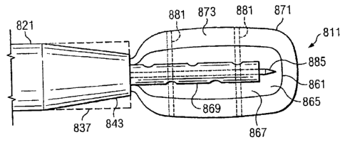
Referring to FIGS. 23-25, a reduced pressure delivery system 811 according to
an
embodiment of the present invention includes a manifold delivery tube 821
having a tapered
distal end 843 that is configured to flex radially outward to an open position
such that the inner
diameter of the distal end 843 would be substantially the same as or greater
than the inner
diameter at other portions of the tube 821. The open position of the distal
end 843 is
schematically illustrated in FIGS. 23-25 by broken lines 837.
The manifold delivery tube 821 further includes a passageway in which a
reduced
pressure delivery apparatus 861 similar to the other reduced pressure delivery
apparatuses
described herein is contained. The reduced pressure delivery apparatus 861
includes a flexible
barrier 865 and/or a cellular material 867 that is preferably rolled, folded,
or otherwise
compressed around a reduced pressure delivery tube 869 to reduce the cross-
sectional area of
the reduced pressure delivery apparatus 861 within the passageway.
An impermeable membrane 871 having an inner space 873 is disposed around the
reduced pressure delivery apparatus 861 such that the reduced pressure
delivery apparatus 861
is contained within the inner space 873 of the impermeable membrane 871. The
impermeable
membrane 871 may be a balloon, a sheath, or any other type of membrane that is
capable of
preventing fluid transmission such that the impermeable membrane 871 can
assume at least
one of a compressed position (see FIG. 23), a relaxed position (see FIG. 24),
and an expanded
position (see FIGS. 25 and 25A). The impermeable membrane 871 may be sealingly
connected to the manifold delivery tube 821 such that the inner space 873 of
the impermeable
membrane 871 is in fluid communication with the passageway of the manifold
delivery tube
821. The impermeable membrane 871 may alternatively be attached to the reduced
pressure
delivery tube 869 such that the inner space 873 of the impermeable membrane
871 is in fluid
communication with the passageway of the reduced pressure delivery tube 869.
The
impermeable membrane 871 instead may be attached to a separate control tube or
control
lumen (see for example FIG. 25A) that fluidly communicates with the inner
space 873.
In one embodiment, the impermeable membrane 871 may be provided to further
reduce
the cross-sectional area of the reduced pressure delivery apparatus 861 within
the passageway.
To accomplish this, a pressure is applied to the inner space 873 of the
impermeable membrane
871 that is less than the ambient pressure surrounding the impermeable
membrane 871. A
23
CA 02810300 2013-03-20
significant portion of the air or other fluid within the inner space 873 is
thereby evacuated,
placing the impermeable membrane 871 in the compressed position illustrated in
FIG. 23. In
the compressed position, the impermeable membrane 871 is drawn inward such
that a
compressive force is applied to the reduced pressure delivery apparatus 861 to
further reduce
the cross-sectional area of the reduced pressure delivery apparatus 861. As
previously
described with reference to FIGS. 21 and 22, the reduced pressure delivery
apparatus 861 may
be delivered to the tissue site following the placement of the distal end 843
of the manifold
delivery tube 821 at the tissue site. Placement and manipulation of the
impermeable
membrane 871 and the reduced pressure delivery apparatus 861 may be
accomplished by using
endoscopy, ultrasound, fluoroscopy, auscultation, palpation, or any other
suitable localization
technique. The impermeable membrane 871 may include radio-opaque markers 881
that
improve visualization of the impermeable membrane 871 under fluoroscopy prior
to its
removal.
After pushing the reduced pressure delivery apparatus 861 through the distal
end 843,
the reduced pressure applied to the inner space 873 may be eased to place the
impermeable
membrane 871 in the relaxed position (see FIG. 24), thereby facilitating
easier removal of the
reduced pressure delivery apparatus 861 from the impermeable membrane 871. A
removal
instrument 885 such as a trocar, stylet, or other sharp instrument may be
provided to rupture
the impermeable membrane 871. Preferably, the removal instrument 885 is
inserted through
the reduced pressure delivery tube 869 and is capable of being advanced into
contact with the
impermeable membrane 871. After rupture of the impermeable membrane 871, the
removal
instrument 885 and the impermeable membrane 871 may be withdrawn through the
manifold
delivery tube 821, allowing the flexible barrier 865 and/or cellular material
867 of the reduced
pressure delivery apparatus 861 to unroll, unfold, or decompress such that the
reduced pressure
delivery apparatus 861 can be placed in contact with the tissue site. The
unrolling of the
flexible barrier 865 and/or cellular material 867 may occur automatically
following the
relaxation of reduced pressure to the inner space 873 and the removal of the
impermeable
membrane 871. In some cases, a positive pressure may be delivered through the
reduced
pressure delivery tube 869 to assist in unrolling or decompressing the
flexible barrier 865
and/or cellular material 867. Following final placement of the reduced
pressure delivery
apparatus 861, the manifold delivery tube 821 is preferably removed from the
patient, but the
reduced pressure delivery tube 869 associated with the reduced pressure
delivery apparatus 861
remains in situ to allow percutaneous application of reduced pressure to the
tissue site.
24
CA 02810300 2013-03-20
The impermeable membrane 871 may also be used to dissect tissue adjacent the
tissue
site prior to placing the reduced pressure delivery apparatus 861 against the
tissue site. After
pushing the reduced pressure delivery apparatus 861 and intact impermeable
membrane 871
through the distal end 843 of the manifold delivery tube 821, air or another
fluid may be
injected or pnmped into the inner space 873 of the impermeable membrane 871. A
liquid is
preferably used to inflate the impermeable membrane 871 since the
incompressibility of liquids
allow the impermeable membrane 871 to expand more evenly and consistently. The
impermeable membrane 871 may expand radially as illustrated in FIG. 25 or
directionally
depending on its method of manufacture and attachment to the manifold delivery
tube 821. As
the impermeable membrane 871 expands outward into the expanded position (see
FIG. 25) due
to the pressure of the air or fluid, a void is dissected adjacent the tissue
site. When the void is
large enough, the liquid, air or other fluid may be released from the inner
space 873 to allow
the impermeable membrane 871 to assume the relaxed position. The impermeable
membrane
871 may then be ruptured as previously explained and the reduced pressure
delivery apparatus
861 inserted adjacent the tissue site.
Referring to FIG. 25A, if the impermeable membrane 871 is used primarily to
dissect
tissue adjacent the tissue site, the impermeable membrane 871 may be sealingly
attached to the
manifold delivery tube 821 such that the inner space 873 fluidly communicates
with a
secondary lumen or tube 891 associated with or attached to the manifold
delivery tube 821.
The secondary lumen 891 may be used to deliver a liquid, air, or other fluid
to the inner space
873 to place the impermeable membrane 871 in the expanded position. Following
dissection,
the impermeable membrane 871 may be relaxed and ruptured as previously
described with
reference to FIG. 24.
Referring to FIG. 26, a reduced pressure delivery system 911 according to an
embodiment of the present invention includes a manifold delivery tube 921
having a tapered
distal end 943 that is configured to flex radially outward to an open position
such that the inner
diameter of the distal end 943 would be substantially the same as or greater
than the inner
diameter at other portions of the tube 921. The open position of the distal
end 943 is
schematically illustrated in FIG. 26 by broken lines 937.
The manifold delivery tube 921 further includes a passageway in which a
reduced
pressure delivery apparatus 961 similar to the other reduced pressure delivery
apparatuses
described herein is contained. The reduced pressure delivery apparatus 961
includes a flexible
barrier 965 and/or a cellular material 967 that is preferably rolled, folded,
or otherwise
25
CA 02810300 2013-03-20
compressed around a reduced pressure delivery tube 969 to reduce the cross-
sectional area of
the reduced pressure delivery apparatus 961 within the passageway of the
manifold delivery
tube 921.
An impermeable membrane 971 having an inner space 973 is disposed around the
reduced pressure delivery apparatus 961 such that the reduced pressure
delivery apparatus 961
is contained within the inner space 973 of the impermeable membrane 971. The
impermeable
membrane 971 includes a glue seal 977 on one end of the impermeable membrane
971 to
provide an alternative method of removing the reduced pressure delivery
apparatus 961 from
the impermeable membrane 971. The impermeable membrane 971 may be sealingly
connected at another end to the manifold delivery tube 921 such that the inner
space 973 of the
impermeable membrane 971 is in fluid communication with the passageway of the
manifold
delivery tube 921. Alternatively, the impermeable membrane 971 may be attached
to a
separate control tube (not shown) that fluidly communicates with the inner
space 973.
Similar to the impermeable membrane 871 of FIG. 23, impermeable membrane 971
may be capable of preventing fluid transmission such that the impermeable
membrane 971 can
assume at least one of a compressed position, a relaxed position, and an
expanded position.
Since the procedures for placing the impermeable membrane 971 in a compressed
position and
an expanded position are similar to those for impermeable membrane 871, only
the differing
process of removing the reduced pressure delivery apparatus 961 is described.
The reduced pressure delivery apparatus 961 is delivered to the tissue site
within the
impermeable membrane 971 and then properly positioned using endoscopy,
ultrasound,
fluoroscopy, auscultation, palpation, or any other suitable localization
technique. The
impermeable membrane 971 may include radio-opaque markers 981 that improve
visualization
of the impermeable membrane 971 under fluoroscopy prior to its removal. The
reduced
pressure delivery apparatus 961 is then pushed through the distal end 943 of
the manifold
delivery tube 921_ The reduced pressure applied to the inner space 973 may be
eased to place
the impermeable membrane 971 in the relaxed position. The reduced pressure
delivery
apparatus 961 is then pushed through the glue seal 977 to exit the impermeable
membrane 971.
Referring to FIG. 26A, a reduced pressure delivery system 985 according to an
embodiment of the present invention may not include a manifold delivery tube
similar to
manifold delivery tube 921 of FIG. 26. Instead, the reduced pressure delivery
system 985 may
include a guide wire 987, a reduced pressure delivery tube 989, and a reduced
pressure
delivery apparatus 991. The reduced pressure delivery apparatus 991 includes a
plurality flow
26
CA 02810300 2013-03-20
channels that is fluidly connected to the reduced pressure delivery tube 989.
Instead of using
an independent manifold delivery tube to deliver the reduced pressure delivery
apparatus 991,
the reduced pressure delivery apparatus 991 and reduced pressure delivery tube
989 are placed
on the guide wire 987, which is percutaneously guided to a tissue site 993.
Preferably, the
guide wire 987 and reduced pressure delivery tube 989 penetrate the skin of
the patient through
a sterile sheath. By guiding the reduced pressure delivery tube 989 and
reduced pressure
delivery apparatus 991 along the guide wire 987, the reduced pressure delivery
apparatus 991
may be placed at the tissue site 993 to allow percutaneous application of
reduced pressure
tissue treatment.
Since the reduced pressure delivery apparatus 991 is not constrained within a
manifold
delivery tube during delivery to the tissue site 993, it is preferable to hold
the reduced pressure
delivery apparatus 991 in a compressed position during delivery. If an elastic
foam is used as
the reduced pressure delivery apparatus 991, a biocompatibIe, soluble adhesive
may be applied
to the foam and the foam compressed. Upon arrival at the tissue site, bodily
fluids or other
fluids delivered through the reduced pressure delivery tube 989 dissolve the
adhesive, allowing
the foam to expand into contact with the tissue site. Alternatively, the
reduced pressure
delivery apparatus 991 may be formed from a compressed, dry hydrogel. The
hydrogel
absorbs moisture following delivery to the tissue site 993 allowing expansion
of the reduced
pressure delivery apparatus 991. Still another reduced pressure delivery
apparatus 991 may be
made from a thermoactive material (e.g. polyethylene glycol) that expands at
the tissue site 993
when exposed to the body heat of the patient. In. still another embodiment, a
compressed
reduced pressure delivery apparatus 991 may be delivered to the tissue site
993 in a dissolvable
membrane.
Referring to FIG. 27, a reduced pressure delivery system 1011 according to an
embodiment of the present invention includes a manifold delivery tube 1021
having a distal
end 1043 that is inserted through a tissue of a patient to access a tissue
site 1025. The tissue
site 1025 may include a void 1029 that is associated with a wound or other
defect, or
alternatively a void may be created by dissection, including the dissection
techniques described
herein.
Following placement of the distal end 1043 within the void 1029 adjacent the
tissue site
1025, an injectable, pourable, or flowable reduced pressure delivery apparatus
1035 is
delivered through the manifold delivery tube 1021 to the tissue site 1025. The
reduced
pressure delivery apparatus 1035 preferably exists in a flowable state during
delivery to the
27
CA 02810300 2013-03-20
tissue site, and then, after arrival forms a plurality of flow channels for
distribution of reduced
pressure or fluids. In some cases, the flowable material may harden into a
solid state after
arrival at the tissue site, either through a drying process, a curing process,
or other chemical or
physical reaction. In other cases, the flowable material may form a foam in-
situ following
delivery to the tissue site. Still other materials may exist in a gel-like
state at the tissue site
1025 but still have a plurality of flow channels for delivering reduced
pressure. The amount of
reduced pressure delivery apparatus 1035 delivered to the tissue site 1025 may
be enough to
partially or completely fill the void 1029. The reduced pressure delivery
apparatus 1035 may
include aspects of both a manifold and a scaffold. As a manifold, the reduced
pressure
delivery apparatus 1035 includes a plurality of pores or open cells that may
be formed in the
material after delivery to the void 1029. The pores or open cells communicate
with one
another, thereby creating a plurality of flow channels. The flow channels are
used to apply and
distribute reduced pressure to the tissue site 1025. As a scaffold, the
reduced pressure delivery
apparatus 1035 is bioresorbable and serves as a substrate upon and within
which new tissue
may grow.
In one embodiment, the reduced pressure delivery apparatus 1035 may include
poragens such as NaC1 or other salts that are distributed throughout a liquid
or viscous gel.
After the liquid or viscous gel is delivered to the tissue site 1025, the
material conforms to the
void 1029 and then cures into a solid mass. The water-soluble NaCI poragens
dissolve in the
presence of bodily fluids leaving a structure with interconnected pores, or
flow channels.
Reduced pressure and/or fluid is delivered to the flow channels. As new tissue
develops, the
tissue grows into the pores of the reduced pressure delivery apparatus 1035,
and then
ultimately replaces the reduced pressure delivery apparatus 1035 as it
degrades. In this
particular example, the reduced pressure delivery apparatus 1035 serves not
only as a
manifold, but also as a scaffold for new tissue growth.
In another embodiment, the reduced pressure delivery apparatus 1035 is an
alginate
mixed with 400 gm marmose beads. The poragens or beads may be dissolved by
local body
fluids or by irrigational or other fluids delivered to the reduced pressure
delivery apparatus
1035 at the tissue site. Following dissolution of the poragens or beads, the
spaces previously
occupied by the poragens or beads become voids that are interconnected with
other voids to
form the flow channels within the reduced pressure delivery apparatus 1035.
The use of poragens to create flow channels in a material is effective, but it
also forms
pores and flow channels that are limited in size to approximately the particle
size of the
28
CA 02810300 2013-03-20
selected poragen. Instead of poragens, a chemical reaction may be used to
create larger pores
due to the formation of gaseous by-products. For example, in one embodiment, a
flowable
material may be delivered to the tissue site 1025 that contains sodium
bicarbonate and citric
acid particles (non-stoichiometric amounts may be used). As the flowable
material forms a
foam or solid in-situ, bodily fluids will initiate an acid-base reaction
between the sodium
bicarbonate and the citric acid. The resulting carbon dioxide gas particles
that are produced
create larger pore and flow channels throughout the reduced pressure delivery
apparatus 1035
than techniques relying on poragen dissolution.
The transformation of the reduced pressure delivery apparatus 1035 from a
liquid or
viscous gel into a solid or a foam can be triggered by pH, temperature, light,
or a reaction with
bodily fluids, chemicals or other substances delivered to the tissue site. The
transformation
may also occur by mixing multiple reactive components. In one embodiment, the
reduced
pressure delivery apparatus 1035 is prepared by selecting bioresorbable
microspheres made
from any bioresorbable polymer. The microspheres are dispersed in a solution
containing a
photoinitiator and a hydrogel-forming material such as hyaluronic acid,
collagen, or
polyethylene glycol with photoreactive groups. The microsphere-gel mixture is
exposed to
light for a brief period of time to partially crosslink the hydrogel and
immobilize the hydrogel
on the microspheres. The excess solution is drained, and the microspheres are
then dried. The
microspheres are delivered to the tissue site by injection or pouring, and
following delivery, the
mixture absorbs moisture, and the hydrogel coating becomes hydrated. The
mixture is then
again exposed to light, which crosslinks the microspheres, creating a
plurality of flow
channels. The crosslinked microspheres then serve as a manifold to deliver
reduced pressure
to the tissue site and as a porous scaffold to promote new tissue growth.
In addition to the preceding embodiments described herein, the reduced
pressure
delivery apparatus 1035 may be made from a variety of materials, including
without limitation
calcium phosphate, collagen, alginate, cellulose, or any other equivalent
material that is
capable of being delivered to the tissue site as a gas, liquid, gel, paste,
putty, slurry,
suspension, or other flowable material and is capable of forming multiple flow
paths in fluid
communication with the tissue site. The flowable material may further include
particulate
solids, such as beads, that are capable of flowing through the manifold
delivery tube 1021 if
the particulate solids are sufficiently small in size. Materials that are
delivered to the tissue site
in a flowable state may polymerize or gel in-situ.
29
CA 02810300 2013-03-20
As previously described, the reduced pressure delivery apparatus 1035 may
injected or
poured directly into the void 1029 adjacent the tissue site 1025. Referring to
FIG. 27A, the
manifold delivery tube 1021 may include an impermeable or semi-permeable
membrane 1051
at the distal end 1043 of the manifold delivery tube 1021. The membrane 1051
includes an
inner space 1055 that fluidly communicates with a secondary lumen 1057
attached to the
manifold delivery tube 1021. The manifold delivery tube 1021 is guided to the
tissue site 1025
over a guide wire 1061.
The reduced pressure delivery apparatus 1035 may be injected or poured through
the
secondary lumen 1057 to fill the inner space 1055 of the membrane 1051. As the
fluid or gel
fills the membrane 1051, the membrane 1051 expands to fill the void 1029 such
that the
membrane is in contact with the tissue site 1025. As the membrane 1051
expands, the
membrane 1051 may be used to dissect additional tissue adjacent or near the
tissue site 1025.
The membrane 1051, if impermeable, may be physically ruptured and removed,
leaving behind
the reduced pressure delivery apparatus 1035 in contact with the tissue site
1025.
Alternatively, the membrane 1051 may be made from a dissolvable material that
dissolves in
the presence of bodily fluids or biocompatible solvents that may be delivered
to the membrane
1051. If the membrane 1051 is semi-permeable, the membrane 1051 may remain in
situ. The
semi-permeable membrane 1051 allows communication of reduced pressure and
possibly other
fluids to the tissue site 1025.
Referring to FIG. 28, a method 1.111 of administering a reduced pressure
tissue
treatment to a tissue site includes at 1115 surgically inserting a manifold
adjacent the tissue
site, the manifold having a plurality of projections extending from a flexible
barrier to create a
plurality of flow channels between the projections. The manifold is positioned
at 1119 such
that at least a portion of the projections are in contact with the tissue
site. At 1123, a reduced
pressure is applied through the manifold to the tissue site.
Referring to FIG. 29, a method 1211 of administering a reduced pressure tissue
treatment to a tissue site includes at 1215 percutaneously inserting a
manifold adjacent the
tissue site. The manifold may include a plurality of projections extending
from a flexible
barrier to create a plurality of flow channels between the projections.
Alternatively, the
manifold may include cellular material having a plurality of flow channels
within the cellular
material. Alternatively, the manifold may be formed from an injectable or
pourable material
that is delivered to the tissue site and forms a plurality of flow channels
after arriving at the
tissue site. At 1219, the manifold is positioned such that at a least a
portion of the flow
30
CA 02810300 2013-03-20
=
channels are in fluid communication with the tissue site. A reduced pressure
is applied to the
tissue site through the manifold at 1223.
Referring to FIG. 30, a method 1311 of administering a reduced pressure tissue
treatment to a tissue site includes at 1315 percutaneously inserting a tube
having a passageway
through a tissue of a patient to place a distal end of the tube adjacent the
tissue site. At 1319, a
balloon associated with the tube may be inflated to dissect tissue adjacent
the tissue site,
thereby creating a void. At 1323, a manifold is delivered through the
passageway. The
manifold may include a plurality of projections extending from a flexible
barrier to create a
plurality of flow channels between the projections. Alternatively, the
manifold may include
cellular material having a plurality of flow channels within the cellular
material. Alternatively,
the manifold may be formed from an injectable or pourable material that is
delivered to the
tissue site as described previously with reference to FIG. 27. The manifold is
positioned in the
void at 1327 such that at least a portion of the flow channels are in fluid
communication with
the tissue site. At 1331, a reduced pressure is applied to the tissue site
through the manifold
via a reduced pressure delivery tube or any other delivery means.
Referring to FIG. 31, a method 1411 of administering a reduced pressure tissue
treatment to a tissue site includes at 1415 percutaneously inserting a tube
having a passageway
through a tissue of a patient to place a distal end of the tube adjacent the
tissue site. At 1423, a
manifold is delivered through the passageway to the tissue site within an
impermeable sheath,
the impermeable sheath at 1419 having been subjected to a first reduced
pressure less than an
ambient pressure of the sheath. At 1427, the sheath is ruptured to place the
manifold in contact
with the tissue site. At 1431, a second reduced pressure is applied through
the manifold to the
tissue site.
Referring to FIGS. 32 and 33, a reduced pressure delivery apparatus 1511
according to
an embodiment of the present invention includes an orthopedic hip prosthesis
1515 for
replacing the existing femoral head of a femur 1517 of a patient. The hip
prosthesis 1515
includes a stem portion 1521 and a head portion 1525. The stem portion'1521 is
elongated for
insertion within a passage 1529 reamed in a shaft of the femur 1517. A porous
coating 1535 is
disposed around the stem portion and preferably is constructed from sintered
or vitrified
ceramics or metal. Alternatively, a cellular material having porous
characteristic could be
= disposed around the stem portion. A plurality of flow channels 1541 is
disposed within the
stern portion 1521 of the hip prosthesis 1515 such that the flow channels 1541
are in fluid
communication with the porous coating 1535. A connection port 1545 is fluidly
connected to
31
CA 02810300 2013-03-20
the flow channels 1541, the port being configured for releasable connection to
a reduced
pressure delivery tube 1551 and a reduced pressure delivery source 1551 The
flow channels
1541 are used to deliver a reduced pressure to the porous coating 1535 and/or
the bone
surrounding the hip prosthesis 1515 following implantation. The flow channels
1541 may
include a main feeder line 1543 that fluidly communicates with several lateral
branch lines
1547, which communicate with the porous coating 1535. The lateral branch lines
1545 may be
oriented normal to the main feeder line 1543 as illustrated in FIG. 32, or may
be oriented at
angles to the main feeder line 1543. An alternative method for distributing
the reduced
pressure includes providing a hollow hip prosthesis, and filling the inner
space of the
prosthesis with a cellular (preferably open-cell) material that is capable of
fluidly
communicating with the porous coating 1535.
Referring more specifically to FIG. 33, hip prosthesis 1515 may further
include a
second plurality of flow channels 1561 within the stem portion 1521 to provide
a fluid to the
porous coating 1535 and/or the bone surrounding the hip prosthesis 1515. The
fluid could
include filtered air or other gases, antibacterial agents, antiviral agents,
cell-growth promotion
agents, irrigation fluids, chemically active fluids, or any other fluid. If it
is desired to introduce
multiple fluids to the bone surrounding the hip prosthesis 1515, additional
paths of fluid
communication may be provided. A connection port 1565 is fluidly connected to
the flow
channels 1561, the port 1565 being configured for releasable connection to a
fluid delivery
tube 1571 and a fluid delivery source 1573. The flow channels 1561 may include
a main
feeder line 1583 that fluidly communicates with several lateral branch lines
1585, which
communicate with the porous coating 1535. The lateral branch lines 1585 may be
oriented
normal to the main feeder line 1583 as illustrated in FIG. 33, or may be
oriented at angles to
the main feeder line 1583.The delivery of reduced pressure to the first
plurality of flow channels 1541 and the
delivery of the fluid to the second plurality of flow channels 1561 may be
accomplished by
separate tubes such as reduced pressure delivery tube 1551 and fluid delivery
tube 1571.
Alternatively, a tube having multiple lumens as described previously herein
may be used to
separate the communication paths for delivering the reduced pressure and the
fluid. It should
further be noted that while it is preferred to provide separate paths of fluid
communication
within the hip prosthesis 1515, the first plurality of flow channels 1541
could be used to
deliver both the reduced pressure and the fluid to the bone surrounding the
hip prosthesis 1515.
32
CA 02810300 2013-03-20
As previously described, application of reduced pressure to bone tissue
promotes and
speeds the growth of new bone tissue. By using the hip prosthesis 1515 as a
manifold to
deliver reduced pressure to the area of bone surrounding the hip prosthesis,
recovery of the
femur 1517 is faster, and the hip prosthesis 1515 integrates more successfully
with the bone.
Providing the second plurality of flow channels 1561 to vent the bone
surrounding the hip
prosthesis 1515 improves the successful generation of new bone around the
prosthesis.
Following the application of reduced pressure through the hip prosthesis 1515
for a
selected amount of time, the reduced pressure delivery tube 1551 and fluid
delivery tube 1571
may be disconnected from the connection ports 1545, 1565 and removed from the
patient's
body, preferably without a surgically-invasive procedure. The connection
between the
connection ports 1545, 1565 and the tubes 1551, 1571 may be a manually-
releasable
connection that is effectuated by applying an axially-oriented tensile force
to the tubes 1551,
1571 on the outside of the patient's body. Alternatively, the connection ports
1545, 1565 may
be bioresorbable or dissolvable in the presence of selected fluids or
chemicals such that release
of the tubes 1551, 1571 may be obtained by exposing the connection ports 1545,
1565 to the
fluid or chemical. The tubes 1551, 1571 may also be made from a bioresorbable
material that
dissolves over a period of time or an activated material that dissolves in the
presence of a
particular chemical or other substance.
The reduced pressure delivery source 1553 may be provided outside the
patient's body
and connected to the reduced pressure delivery tube 1551 to deliver reduced
pressure to the hip
prosthesis 1515. Alternatively, the reduced pressure delivery source 1553 may
be implanted
within the patient's body, either on-board or near the hip prosthesis 1515.
Placement of the
reduced pressure delivery source 1553 within the patient's body eliminates the
need for a
percutaneous fluid connection. The implanted reduced pressure delivery source
1553 may be a
traditional pump that is operably connected to the flow channels 1541. The
pump may be
powered by a battery that is implanted within the patient, or may be powered
by an external
battery that is electrically and percutaneously connected to the pump. The
pump may also be
driven directly by a chemical reaction that delivers a reduced pressure and
circulates fluids
through the flow channels 1541, 1561.
While only the stem portion 1521 and head portion 1525 of the hip prosthesis
1515 are
illustrated in FIGS. 32 and 33, it should be noted that the flow channels and
means for
applying reduced pressure tissue treatment described herein could be applied
to any component
33
CA 02810300 2013-03-20
of the hip prosthesis 1515 that contacts bone or other tissue, including for
example the
acetabular cup.
Referring to FIG. 34, a method 1611 for repairing a joint of a patient
includes at 1615
implanting a prosthesis within a bone adjacent the joint. The prosthesis could
be a hip
prosthesis as described above or any other prosthesis that assists in
restoring mobility to the
joint of the patient. The prosthesis includes a plurality of flow channels
configured to fluidly
communicate with the bone. At 1619, a reduced pressure is applied to the bone
through the
plurality of flow channels to improve oseointegration of the prosthesis.
Referring to FIG. 35 and 36, a reduced pressure delivery apparatus 1711
according to
an embodiment of the present invention includes an orthopedic fixation device
1715 for
securing a bone 1717 of a patient that includes a fracture 1719 or other
defect. The orthopedic
fixation device 1715 illustrated in FIGS. 35 and 36 is a plate having a
plurality of passages
1721 for anchoring the orthopedic fixation device 1715 to the bone 1717 with
screws 1725,
pins, bolts, or other fasteners. A porous coating 1735 may be disposed on a
surface of the
orthopedic fixation device 1715 that is to contact the bone 1717. The porous
coating is
preferably constructed from sintered or vitrified ceramics or metal.
Alternatively, a cellular
material having porous characteristic could be disposed between the bone 1717
and the
orthopedic fixation device 1715. A plurality of flow channels 1741 is disposed
within the
orthopedic fixation device 1715 such that the flow channels 1741 are in fluid
communication
with the porous coating 1735. A connection port 1745 is fluidly connected to
the flow
channels 1741, the port being configured for connection to a reduced pressure
delivery tube
1751 and a reduced pressure delivery source 1753. The flow channels 1741 are
used to deliver
a reduced pressure to the porous coating 1735 and/or the bone surrounding the
orthopedic
fixation device 1715 following fixation of the orthopedic fixation device 1715
to the bone
1717. The flow channels 1741 may include a main feeder line 1743 that fluidly
communicates
with several lateral branch lines 1747, which communicate with the porous
coating 1735. The
lateral branch lines 1747 may be oriented normal to the main feeder line 1743
as illustrated in
FIG. 35, or may be oriented at angles to the main feeder line 1743. An
alternative method for
distributing the reduced pressure includes providing a hollow orthopedic
fixation device, and
filling the inner space of the orthopedic fixation device with a cellular
(preferably open-cell)
material that is capable of fluidly communicating with the porous coating
1735.
The orthopedic fixation device 1715 may be a plate as shown in FIG. 35, or
alternatively may be a fixation device such as a sleeve, a brace, a strut, or
any other device that
34
CA 02810300 2013-03-20
is used to stabilize a portion of the bone. The orthopedic fixation device
1715 may further be
fasteners used to attach prosthetic or other orthopedic devices or implanted
tissues (e.g. bone
tissues or cartilage), provided that the fasteners include flow channels for
delivering reduced
pressure to tissue adjacent to or surrounding the fasteners. Examples of these
fasteners may
include pins, bolts, screws, or any other suitable fastener.
Referring more specifically to FIG. 36, the orthopedic fixation device 1715
may further
include a second plurality of flow channels 1761 within the orthopedic
fixation device 1715 to
provide a fluid to the porous coating 1735 and/or the bone surrounding the
orthopedic fixation
device 1715. The fluid could include filtered air or other gases,
antibacterial agents, antiviral
agents, cell-growth promotion agents, irrigation fluids, chemically active
agents, or any other
fluid. If it is desired to introduce multiple fluids to the bone surrounding
the orthopedic
fixation device 1715, additional paths of fluid communication may be provided.
A connection
port 1765 is fluidly connected to the flow channels 1761, the port 1765 being
configured for
connection to a fluid delivery tube 1771 and a fluid delivery source 1773. The
flow channels
1761 may include a main feeder line 1783 that fluidly communicates with
several lateral
branch lines 1785, which communicate with the porous coating 1735. The lateral
branch lines
1785 may be oriented normal to the main feeder line 1783 as illustrated in
FIG. 33, or may be
oriented at angles to the main feeder line 1783.
The delivery of reduced pressure to the first plurality of flow channels 1741
and the
delivery of the fluid to the second plurality of flow channels 1761 may be
accomplished by
separate tubes such as reduced pressure delivery tube 1751 and fluid delivery
tube 1771.
Alternatively, a tube having multiple lumens as described previously herein
may be used to
separate the communication paths for delivering the reduced pressure and the
fluid. It should
further be noted that while it is preferred to provide separate paths of fluid
communication
within the orthopedic fixation device 1715, the first plurality of flow
channels 1741 could be
used to deliver both the reduced pressure and the fluid to the bone adjacent
the orthopedic
fixation device 1715.
The use of orthopedic fixation device 1715 as a manifold to deliver reduced
pressure to
the area of bone adjacent the orthopedic fixation device 1715 speeds and
improves recovery of
the defect 1719 of the bone 1717. Providing the second plurality of flow
channels 1761 to
communicate fluids to the bone surrounding the orthopedic fixation device 1715
improves the
successful generation of new bone near the orthopedic fixation device.
35
CA 02810300 2013-03-20
Referring to FIG. 37, a method 1811 for healing a bone defect of a bone
includes at
1815 fixating the bone using an orthopedic fixation device. The orthopedic
fixation device
includes a plurality of flow channels disposed within the orthopedic fixation
device. At 1819,
a reduced pressure is applied to the bone defect through the plurality of flow
channels.
Referring to FIG. 38, a method 1911 for administering reduced pressure tissue
treatment to a tissue site includes at 1915 positioning a manifold having a
plurality of flow
channels such that at least a portion of the flow channels are in fluid
communication with the
tissue site. A reduced pressure is applied at 1919 to the tissue site through
the flow channels,
and a fluid is delivered at 1923 to the tissue site through the flow channels
Referring to FIG. 39, a method 2011 for administering reduced pressure tissue
treatment to a tissue site includes at 2015 positioning a distal end of a
manifold delivery tube
adjacent the tissue site. At 2019 a fluid is delivered through the manifold
delivery tube to the
tissue site. The fluid is capable of filling a void adjacent the tissue site
and becoming a solid
manifold having a plurality of flow channels in fluid communication with the
tissue site. A
reduced pressure is applied at 2023 to the tissue site through the flow
channels of the solid
manifold.
Referring to FIGS. 40-48, a reduced pressure delivery system 2111 includes a
primary
manifold 2115 having a flexible wall 2117 surrounding a primary flow passage
2121. The
flexible wall 2117 is connected at a proximal end 2123 to a reduced pressure
delivery tube
2125. Since the shape of the reduced pressure delivery tube 2125 will
typically be round in
cross-section, and since the shape of the primary manifold 2115 in cross-
section may be other
than round (i.e. rectangular in FIGS. 40-45 and triangular in FIGS. 46-48), a
transition region
2129 is provided between the reduced pressure delivery tube 2125 and the
primary manifold
2115. The primary manifold 2115 may be adhesively connected to the reduced
pressure
delivery tube 2125, connected using other means such as fusing or insert
molding, or
alternatively may be integrally connected by co-extrusion. The reduced
pressure delivery tube
2125 delivers reduced pressure to the primary manifold 2115 for distribution
at or near the
tissue site.
A blockage prevention member 2135 is positioned within the primary manifold to
prevent collapse of the manifold 2115, and thus blockage of the primary flow
passage 2121
during application of reduced pressure. In one embodiment, the blockage
prevention member
2135 may be a plurality of projections 2137 (see FIG. 44) disposed on an inner
surface 2141 of
the flexible wall 2117 and extending into the primary flow passage 2121. In
another
36
=
CA 02810300 2013-03-20
embodiment, the blockage prevention member 2135 may be a single or multiple
ridges 2145
disposed on the inner surface 2141 (see FIGS. 40 and 41). In yet another
embodiment, the
blockage prevention member 2135 may include a cellular material 2149 disposed
within the
primary flow passage such as that illustrated in FIG. 47. The blockage
prevention member
2135 may be any material or structure that is capable of being inserted within
the flow passage
or that is capable of being integrally or otherwise attached to the flexible
wall 2117. The
blockage prevention member 2135 is able to prevent total collapse of the
flexible wall 2117,
while still allowing the flow of fluids through the primary flow passage 2121.
The flexible wall 2117 further includes a plurality of apertures 2155 through
the
flexible wall 2117 that communicate with the primary flow passage 2121. The
apertures 2155
allow reduced pressure delivered to the primary flow passage 2121 to be
distributed to the
tissue site. Apertures 2155 may be selectively positioned around the
circumference of the
manifold 2115 to preferentially direct the delivery of vacuum. For example, in
FIG. 51,
apertures may be placed facing the bone, facing the overlying tissue, or both.
The reduced pressure delivery tube 2125 preferably includes a first conduit
2161
having at least one outlet fluidly connected to the primary flow passage 2121
to deliver
reduced pressure to the primary flow passage 2121. A second conduit 2163 may
also be
provided to purge the primary flow passage 2121 and the first conduit 2161
with a fluid to
prevent or resolve blockages caused by wound exudate and other fluids drawn
from the tissue
site. The second conduit 2163 preferably includes at least one outlet
positioned proximate to at
least one of the primary flow passage 2121 and the at least one outlet of the
first conduit 2161.
Referring more specifically to FIGS. 40 and 41, the reduced pressure delivery
system
2111 the second conduit 2163 may include multiple conduits for purging the
primary flow
passage 2121 and the first conduit 2161. While the end of the flexible wall
2117 opposite the
end attached to reduced pressure delivery tube 2125 may be open as illustrated
in FIG. 40, it
has been found that capping the end of the flexible wall 2117 may improve the
performance
and reliability of the purging function. Preferably, a head space 2171 is
provided for between
the capped end of the flexible wall and the end of the second conduits 2163.
The head space
2171 allows for a buildup of purge fluid during the purging process, which
helps drive the
purge fluid through the primary flow passage 2121 and into the first conduit
2161.
Also illustrated in FIG. 41 is the divider that serves as the blockage
prevention member
2135. The centrally-located divider bifurcates the primary flow passage 2121
into two
37
CA 02810300 2013-03-20
chambers, which allows continued operation of the primary manifold 2115 if one
of the
chambers becomes blocked and purging is unable to resolve the blockage.
Referring to FIGS. 49 and 50, a reduced pressure delivery system 2211 includes
a
primary manifold 2215 that is integral to a reduced pressure delivery tube
2217. The reduced
pressure delivery tube 2217 includes a central lumen 2223 and a plurality of
ancillary lumens
2225. While the ancillary lumens 2225 may used to measure pressure at or near
the tissue site,
the ancillary lumens 2225 may further be used to purge the central lumen 2223
to prevent or
resolve blockages. A plurality of apertures 2231 communicate with the central
lumen 2223 to
distribute the reduced pressure delivered by the central lumen 2223. As
illustrated in FIG. 50,
it is preferred that the apertures 2231 not penetrate the ancillary lumens
2225. Also illustrated
in FIG. 50 is the countersunk end of the reduced pressure delivery tube, which
creates a head
space 2241 beyond the end of the ancillary lumens 2225. If tissue, scaffolds,
or other materials
were to engage the end of the reduced pressure delivery tube 2217 during
application of
reduced pressure, the head space 2241 would continue to allow purging fluid to
be delivered to
the central lumen 2223.
In operation, the reduced pressure delivery systems 2111, 2211 of FIGS. 40-50
may be
applied directly to a tissue site for distributing reduced pressure to the
tissue site. The low-
profile shape of the primary manifolds is highly desirous for the percutaneous
installation and
removal techniques described herein. Similarly, the primary manifolds may also
be inserted
surgically.
Referring to FIG. 51, the primary manifolds 2115, 2215 may be used in
conjunction
with a secondary manifold 2321. In FIG. 51, the secondary manifold
2321includes a two-
layered felted mat. The first layer of the secondary manifold 2321 is placed
in contact with a
bone tissue site that includes a bone fracture. The primary manifold 2115 is
placed in contact
with the first layer, and the second layer of the secondary manifold 2321 is
placed on top of the
primary manifold 2115 and first layer. The secondary manifold 2321 allows
fluid
communication between the primary manifold 2115 and the tissue site, yet
prevents direct
contact between the tissue site and the primary manifold 2115.
Preferably, the secondary manifold 2321 is bioabsorbable, which allows the
secondary
manifold 2321 to remain in situ following completion of reduced pressure
treatment. Upon
completion of reduced pressure treatment, the primary manifold 2115 may be
removed from
between the layers of the secondary manifold with little or no disturbance to
the tissue site. In
38
CA 02810300 2013-03-20
one embodiment, the primary manifold may be coated with a lubricious material
or a hydrogel-
fanning material to ease removal from between the layers.
The secondary manifold preferably serves as a scaffold for new tissue growth.
As a
scaffold, the secondary manifold may be comprised of at least one material
selected from the
group of polylactic acid, polyglycolic acid, polycaprolactone,
polyhydroxybutyrate,
polyhydroxyvalerate, polydioxanone, polyorthoesthers, polyphosphazenes,
polyurethanes,
collagen, hyaluronic acid, chitosan, hydroxyapatite, calcium phosphate,
calcium sulfate,
calcium carbonate, bioglass, stainless steel, titanium, tantalum, allografts,
and autografts.
The purging function of the reduced pressure delivery systems 2111, 2211
described
above may be employed with any of the manifolds described herein. The ability
to purge a
manifold or a conduit delivering reduced pressure prevents blockages from
forming that hinder
the administration of reduced pressure. These blockages typically form as the
pressure near
the tissue site reaches equilibrium and egress of fluids around the tissue
site slows. It has been
found that purging the manifold and reduced pressure conduit with air for a
selected amount of
time at a selected interval assists in preventing or resolving blockages.
More specifically, air is delivered through a second conduit separate from a
first
conduit that delivers reduced pressure. An outlet of the second conduit is
preferably proximate
to the manifold or an outlet of the first conduit. While the air may be
pressurized and "pushed"
to the outlet of the second conduit, the air is preferably drawn through the
second conduit by
the reduced pressure at the tissue site. It has been found that delivery of
air for two (2) seconds
at intervals of sixty (60) seconds during the application of reduced pressure
is sufficient to
prevent blockages from forming in many instances. This purging schedule
provides enough air
to sufficiently move fluids within the manifold and first conduit, while
preventing the
introduction of too much air. Introducing too much air, or introducing air at
too high of an
interval frequency will result in the reduced pressure system not being able
to return to the
target reduced pressure between purge cycles. The selected amount of time for
delivering a
purging fluid and the selected interval at which the purging fluid is
delivered will typically
vary based on the design and size of system components (e.g. the pump, tubing,
etc.).
However, air should be delivered in a quantity and at a frequency that is ligh
enough to
sufficiently clear blockages while allowing the full target pressure to
recover between purging
cycles.
Referring to FIG. 52, in one illustrative embodiment, a reduced pressure
delivery
system 2411 includes a manifold 2415 fluidly connected to a first conduit 2419
and a second
39
CA 02810300 2013-03-20
conduit 2423. The first conduit 2419 is connected to a reduced pressure source
2429 to
provide reduced pressure to the manifold 2415. The second conduit 2423
includes an outlet
2435 positioned in fluid communication with the manifold 2415 and proximate an
outlet of the
first conduit 2419. The second conduit 2423 is fluidly connected to a valve
2439, which is
capable of allowing communication between the second conduit 2423 and the
ambient air
when the valve is placed in an open position. The valve 2439 is operably
connected to a
controller 2453 that is capable of controlling the opening and closing of the
valve 2439 to
regulate purging of the second conduit with ambient air to prevent blockages
within the
manifold 2415 and the first conduit 2419.
It should be noted that any fluid, including liquids or gases, could be used
to
accomplish the purging techniques described herein. While the driving force
for the purging
fluid is preferably the draw of reduced pressure at the tissue site, the fluid
similarly could be
delivered by a fluid delivery means similar to that discussed with reference
to FIG. 9.
The administration of reduced pressure tissue treatment to a tissue site in
accordance
with the systems and methods described herein may be accomplished by applying
a sufficient
reduced pressure to the tissue site and then maintaining that sufficient
reduced pressure over a
selected period of time. Alternatively, the reduced pressure that is applied
to the tissue site
may be cyclic in nature. More specifically, the amount of reduced pressure
applied may be
varied according to a selected temporal cycle. Still another method of
applying the reduced
pressure may vary the amount of reduced pressure randomly. Similarly, the rate
or volume of
fluid delivered to the tissue site may be constant, cyclic, or random in
nature. Fluid delivery, if
cyclic, may occur during application of reduced pressure, or may occur during
cyclic periods in
which reduced pressure is not being applied. While the amount of reduced
pressure applied to
a tissue site will typically vary according to the pathology of the tissue
site and the
circumstances under which reduced pressure tissue treatment is administered,
the reduced
pressure will typically be between about -5 rum Hg and -500 nun Hg, but more
preferably
between about -5 mm Hg and -300 mm Hg.
While the systems and methods of the present invention have been described
with
reference to tissue growth and healing in human patients, it should be
recognized that these
systems and methods for applying reduced pressure tissue treatment can be used
in any living
organism in which it is desired to promote tissue growth or healing.
Similarly, the systems and
methods of the present invention may be applied to any tissue, including
without limitation
bone tissue, adipose tissue, muscle tissue, neural tissue, dermal tissue,
vascular tissue,
40
CA 02810300 2013-03-20
connective tissue, cartilage, tendons, or ligaments. While the healing of
tissue may be one
focus of applying reduced pressure tissue treatment as described herein, the
application of
reduced pressure tissue treatment, especially to tissues located beneath a
patient's skin, may also
be used to generate tissue growth in tissues that are not diseased, defective,
or damaged. For
example, it may be desired to use the percutaneous implantation techniques to
apply reduced
pressure tissue treatment to grow additional tissue at a tissue site that can
then be harvested.
The harvested tissue may be transplanted to another tissue site to replace
diseased or damaged
tissue, or alternatively the harvested tissue may be transplanted to another
patient.
It is also important to note that the reduced pressure delivery apparatuses
described
herein may be used in conjunction with scaffold material to increase the
growth and growth rate
of new tissue. The scaffold material could be placed between the tissue site
and the reduced
pressure delivery apparatus, or the reduced pressure delivery apparatus could
itself be made
from bioresorbable material that serves as a scaffold to new tissue growth.
It should be apparent from the foregoing that an invention having significant
advantages has been provided. While the invention is shown in only a few of
its forms, it is not
just limited but is susceptible to various changes and modifications without
departing from the
scope thereof.
41