Note: Descriptions are shown in the official language in which they were submitted.
CA 02810412 2013-03-05
WO 2012/037645 1 PCT/CA2011/001027
WELLBORE FRAC TOOL WITH INFLOW CONTROL
FIELD
The invention relates to a method and apparatus for wellbore fluid treatment
and, in particular, to
a method and apparatus for selective communication to a wellbore for fluid
treatment and
effectively handling produced fluids.
BACKGROUND
An oil or gas well relies on inflow of petroleum products. When natural inflow
from the well is
not economical, the well may require wellbore treatment termed stimulation.
This is
accomplished by pumping stimulation fluids such as fracturing fluids, acid,
cleaning chemicals
and/or proppant laden fluids to improve wellbore inflow.
In one previous method, the well is isolated in segments and one or more
segments are
individually treated so that concentrated and controlled fluid treatment can
be provided along the
wellbore by injecting the wellbore stimulation fluids from a tubing string
through a port in the
segment and into contact with the formation. After wellbore fluid treatment,
the stimulation
fluids are sometimes allowed to back flow from the formation into the wellbore
tubing string.
Thereafter, fluids are produced from the formation. In some embodiments, the
produced fluids
also enter the tubing string for flow to the surface. Such wellbore treatment
systems are
described in US Patents 7,748,460 and 7,543,634 and PCT application
PCT/CA2009/000599.
It may be advantageous in certain circumstances to control the inflow of
produced fluids. For
example, it may be advantageous to screen the produced fluids before they
enter the tubing
string. In addition or alternately, the produced fluids may require flow rate
control, as by use of
chokes including devices called inflow control devices (ICD).
Where a wellbore frac tool also provides for inflow control, it is useful if
fracing fluids not be
forced out through the same ports that offer inflow control.
CA 02810412 2013-03-05
WO 2012/037645 2 PCT/CA2011/001027
SUMMARY
In accordance with a broad aspect of the present invention, there is provided
an apparatus for
fluid treatment of a borehole, the apparatus comprising: a tubular body having
a long axis and an
upper end, a first port opened through the wall of the tubular body, a second
port opened through
the wall of the tubular body, the second port axially offset from the first
port and having a fluid
inflow controller positioned to control the flow of fluid into the tubular
body through the port; a
sliding sleeve valve in the tubular body moveable from (i) a first position
closing the first port
and the second port to (ii) a second position closing the second port and
permitting fluid flow
through the first port and to (iii) a third position closing the first port
and permitting fluid flow
through the second port; a sleeve actuator for actuating the sliding sleeve
valve to move from the
first position to the second position in response to a force applied thereto;
a releasable lock for
locking the sliding sleeve valve in the first position and selected to
maintain the sliding sleeve
valve in the first position after the force is removed; and a lock release
mechanism configured to
actuate the releasable lock to release the sliding sleeve valve to move into
the third position.
There is also provided a method for fluid treatment of a borehole, the method
comprising:
running a tubing string into a wellbore to a desired position for treating the
wellbore; opening a
frac port by application of a force to a sliding sleeve valve for the port;
injecting stimulating
fluids through the frac port; releasably locking the sliding sleeve valve in
an open position to
allow flowback of the stimulating fluid; unlocking the sliding sleeve valve to
close the port and
open a fluid control port; and permitting fluid to pass from the wellbore into
the tool through the
fluid control port.
It is to be understood that other aspects of the present invention will become
readily apparent to
those skilled in the art from the following detailed description, wherein
various embodiments of
the invention are shown and described by way of illustration. As will be
realized, the invention
is capable for other and different embodiments and its several details are
capable of modification
in various other respects, all without departing from the spirit and scope of
the present invention.
CA 02810412 2013-03-05
WO 2012/037645 3 PCT/CA2011/001027
Accordingly the drawings and detailed description are to be regarded as
illustrative in nature and
not as restrictive.
BRIEF DESCRIPTION OF THE DRAWINGS
A further, detailed, description of the invention, briefly described above,
will follow by reference
to the following drawings of specific embodiments of the invention. These
drawings depict only
typical embodiments of the invention and are therefore not to be considered
limiting of its scope.
In the drawings:
FIG. I a is a sectional view along the long axis of a frac tool in the form of
a tubing string sub
containing a sleeve in a closed port position;
FIG. lb is a sectional view along the sub of Figure la with the sleeve in a
position allowing fluid
flow through fluid treatment ports;
FIG. 1 c is a sectional view along the sub of Figure la with the sleeve in a
position allowing fluid
flow through fluid control ports;
FIG. 2a is a sectional view through a wellbore having positioned therein a
fluid treatment
assembly according to the present invention;
FIG. 2b is an enlarged view of a portion of the wellbore of FIG. 2a with the
fluid treatment
assembly also shown in section;
FIG. 2b is a view corresponding to FIG. 2b with the fluid treatment assembly
in the next stage of
operation;
FIG. 3a is a quarter sectional view along the long axis of a tubing string sub
useful in the present
invention containing a sleeve and fluid treatment ports;
CA 02810412 2013-03-05
WO 2012/037645 4 PCT/CA2011/001027
FIG. 3b is a side elevation of a flow control sleeve positionable in the sub
of FIG. 3a; and
FIG.s 4a, 4b, 4c and 4d are axial sectional views of a sleeve valve in run in,
intermediate, fluid
treatment intermediate and inflow controlled positions, respectively,
according to one aspect of
the present invention.
DETAILED DESCRIPTION
The description that follows, and the embodiments described therein, is
provided by way of
illustration of an example, or examples, of particular embodiments of the
principles of various
aspects of the present invention. These examples are provided for the purposes
of explanation,
and not of limitation, of those principles and of the invention in its various
aspects. The drawings
are not necessarily to scale and in some instances proportions may have been
exaggerated in
order more clearly to depict certain features. Throughout the drawings, from
time to time, the
same number is used to reference similar, but not necessarily identical,
parts. It is noted, for
example, that the running tool of FIGs 1 differs from that of FIGs 2 and 3 in
some ways although
some identical numbering is used in the two sets of figures.
A method and apparatus has been invented which provides for injecting of a
wellbore treatment
fluid and then reconfiguration to control the flow of produced fluids. The
apparatus and methods
of the present invention can be used in various borehole conditions including
open holes, cased
holes, vertical holes, horizontal holes, straight holes or deviated holes.
In one embodiment, there is provided an apparatus for fluid treatment of a
borehole, the
apparatus comprising: a tubular body having a long axis and an upper end, a
first port opened
through the wall of the tubular body, a second port opened through the wall of
the tubular body,
the second port axially offset from the first port and having a fluid inflow
controller positioned to
control the flow of fluid into the tubular body through the port; a sliding
sleeve valve in the
tubular body moveable from (i) a first position closing the first port and the
second port to (ii) a
second position closing the second port and permitting fluid flow through the
first port and to
(iii) a third position closing the first port and permitting fluid flow
through the second port; a
sleeve actuator for actuating the sliding sleeve valve to move from the first
position to the second
CA 02810412 2013-03-05
WO 2012/037645 5 PCT/CA2011/001027
position in response to a force applied thereto; a releasable lock for locking
the sliding sleeve
valve in the first position and selected to maintain the sliding sleeve valve
in the first position
after the force is removed; and a lock release mechanism configured to actuate
the releasable
lock to release the sliding sleeve valve to move into the third position.
The fluid inflow controller may be selected to control any of various features
of the fluid. For
example, the fluid inflow controller may include one or more of a screen for
filtering out
oversize solids from the fluid or a choke for controlling the pressure drop
and/or flow rate of the
fluid passing through the second port. One type of choke is commonly known as
an inflow
control device (ICD). ICDs use various mechanisms to control flow rate and
pressure drop such
as labyrinths, surface roughening, passage arrangements, nozzles, gates, etc.
In one embodiment, the sleeve actuator is a manipulation string that is run in
to engage the sleeve
and move it to the second position. In yet another embodiment, the sleeve
actuator is a motor
drive. Of course, other actuators are possible. Preferably, however, the
sleeve is actuated
remotely, without the need to trip a work string such as a tubing string or a
wire line. In another
embodiment, therefore, the sleeve actuator includes a seat formed on the
sliding sleeve valve and
a plug sized to land in and seal against the seat, such that a pressure can be
built up such that
fluid pressure force is applied to move the sleeve. In yet another embodiment,
the sleeve may be
of the pressure chamber type, as described in the above-noted PCT application.
The releasable lock may take various forms provided it is actuable to lock the
sleeve in the
second position and maintain it there even when the force that originally
drove the sleeve to the
second position is removed. The releasable lock may include, for example, one
or more catches
such as one or more of a collet, a locking dog, a snap ring, spring loaded
detents, a section of
enlarged diameter, etc. and a corresponding site such as a groove, hole,
protrusion onto which
the lock may engage.
The lock release mechanism may take various forms as well. Its form may depend
on the form
of the releasable lock. In one embodiment, the lock release mechanism is a
manipulation string
that is run in to engage the sleeve and move it from the second position to
the third position. In
CA 02810412 2013-03-05
WO 2012/037645 6 PCT/CA2011/001027
another embodiment, the lock release mechanism is a lock removal feature of
the releasable lock
environment that is actuated by a drilling tool run to remove the ball seats
and clean out the ID of
the tubular.
In one embodiment, the tubular body includes ends formed for connection into a
tubing string,
such as a production string, casing, work string, etc. As such the tool can be
incorporated into a
tubing string for placement in a wellbore. The string may include other
components such as
further frac tools, packers, centralizers, etc. The packers can be of any
desired type to seal
between the wellbore and the tubing string. In one embodiment, at least one of
the first, second
and third packer is a solid body packer including multiple packing elements.
In such a packer, it
is desirable that the multiple packing elements are spaced apart.
In view of the foregoing there is provided a method for fluid treatment of a
borehole, the method
comprising: providing an apparatus for wellbore treatment according to one of
the various
embodiments of the invention; running the tubing string into a wellbore in a
desired position for
treating the wellbore; opening a frac tool port by application of a force to a
sliding sleeve valve
for the port; injecting stimulating fluids through the port; releasably
locking the sliding sleeve
valve in an open position to allow flowback of the stimulating fluid;
unlocking the sliding sleeve
valve to close the port and open a fluid control port; and permitting fluid to
pass from the
wellbore into the tool through the fluid control port.
In one method according to the present invention, the fluid treatment is
borehole stimulation
using stimulation fluids such as one or more of acid, gelled acid, gelled
water, gelled oil, CO2,
nitrogen and any of these fluids containing proppants, such as for example,
sand or bauxite. The
method can be conducted in an open hole or in a cased hole. In a cased hole,
the casing may have
to be perforated prior to running the tubing string into the wellbore, in
order to provide access to
the formation.
In an open hole, the packers may include solid body packers including a solid,
extrudable
packing element and, in some embodiments, solid body packers include a
plurality of extrudable
CA 02810412 2013-03-05
WO 2012/037645 7 PCT/CA2011/001027
packing elements. The first packer and the second packer can be formed as a
solid body packer
including multiple packing elements, for example, in spaced apart relation.
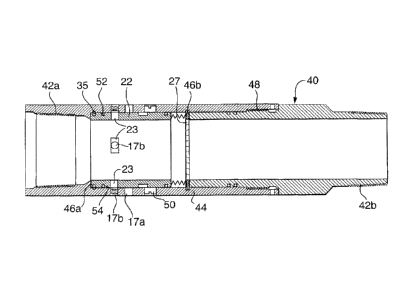
Referring to FIGS. la, lb and lc, a frac tool with inflow control is shown.
The tool is in the
form of a tubing string sub having a tubular body 40, one or more first ports
17a, one or more
second ports 17b axially offset from the first ports and a sleeve 22.
First set of ports 17a are suitable for injecting stimulating fluid
therethrough from the body's
inner bore to its outer surface. As such ports 17a may be generally free of
inserts that reduce the
effectiveness of stimulating fluid being injected outwardly therethrough. For
example, where the
ports are intended for fracturing treatment of the formation, they may be free
of any inserts or
may contain outflow force increasing nozzles etc. that increase the fracturing
effect of the fluid
as it passes out from the tubular. Ports intended for fracturing treatment
therethrough are
generally free of screens, inflow restricting chokes, etc., as these devices
generally reduce the
force of or interfere with outflows.
Second set of ports 17b are configured to control fluid passing inwardly
therethrough and may
contain inserts that effect a control on the fluid. For example, an inflow
control device 19a that
is configured to effect the flow rate and/or pressure drop of fluid passing
therethrough and/or a
screen 19b to filter oversize particles, both of which are shown in this
embodiment. Although
ports 17b are shown axially below ports 17a, this is not necessary. The axial
placement of the
ports could be reversed provided the sleeve is configured and installed to
move in such a way
that permits ports 17a and ports 17b to be opened each in turn.
The sleeve is axially slideable along internally or externally of the tubular
body and is moveable
through a plurality of positions to regulate fluid flow into and out of the
tubular body. In a first
position (FIG. la), sleeve 22 is positioned over first ports 17a and second
ports 17b to close all of
them against fluid flow therethrough. In a second position, as shown in FIG.
lb, the sleeve is
moved such that ports 17a are open and fluid can flow therethrough, while
ports 17b remain
closed. In a third position (FIG. 1c), sleeve 22 is moved to close fluid flow
through ports 17a,
while ports 17b are open to fluid flow therethrough. As such, in the first
position the tubular is
CA 02810412 2013-03-05
WO 2012/037645 8 PCT/CA2011/001027
suitable for at least run in procedures, in the second position, the frac tool
is suitable for injecting
stimulating fluid through ports 17a into the surrounding wellbore and in the
third position, the
tool is suitable for accepting flow back of production fluids, controlling
their flow as they enter
the tubular body.
Sleeve 22 is moveable between the three positions.
The sub 40 includes threaded ends 42a, 42b for connection into a tubing
string. Sub includes a
wall 44 having formed on its inner surface a cylindrical groove 46 for
retaining sleeve 22.
Shoulders 46a, 46b define the ends of the groove 46 and shoulder 46a and an
annular recess 46c
creates a stop for limiting the range of movement of the sleeve within the
groove. Shoulders 46a,
46b and recess 46c can be formed in any way as by casting, milling, etc. the
wall material of the
sub or by threading parts together, as at connection 48. The tubing string if
preferably formed to
hold pressure. Therefore, any connection should, in the preferred embodiment,
be selected to be
substantially pressure tight.
In this illustrated embodiment, sleeve 22 has one or more sleeve ports 23. As
illustrated, in this
embodiment, when in the first position, sleeve 22 is positioned with sleeve
ports 23 positioned
radially over a solid portion of tubular body wall 44 and are neither aligned
with ports 17a nor
ports 17b. As such, a solid portion of sleeve 22 is positioned over, blocking
flow through, ports
17a, 17b. When in the second and third positions, the sleeve is moved such
that sleeve ports 23
align with ports 17a and ports 17b, respectively.
Shear pins 50 are secured between wall 44 and sleeve 22 to hold the sleeve in
the first position.
An actuator is provided for moving sleeve 22 from the first position to the
second position. The
actuator may be any device or method, numerous of which are known. In this
illustrated
embodiment, the actuator includes a plug and a seat formed on the sleeve. A
plug in the form of
a ball 24 is used to land in seat 26 and with fluid pressure apply a force to
shear pins 50 and to
move the sleeve from the first position to the second position. In particular,
the inner facing
surface of sleeve 22 defines a seat 26 having a diameter Dseat, and ball 24,
is sized, having a
CA 02810412 2013-03-05
WO 2012/037645 9 PCT/CA2011/001027
diameter Dball, to pass through the drift diameter Dd of the tubular body but
engage and seal
against seat 26. When pressure is applied, as shown by arrows P, against ball
24, shears 50 will
release allowing sleeve 22 to be driven toward shoulder 46b until collet
fingers 27 land in recess
46c and the sleeve is stopped. The length of the sleeve and location of the
ports 23 are selected
with consideration as to the distance between recess 46c and ports 17a to
permit ports 23 to be
aligned with ports 17a, to open ports 17a to some degree, when the sleeve is
driven into
engagement with recess 46c.
The frac tool may be resistant to fluid flow outwardly therefrom except
through open ports 17a
and fluid cannot pass downwardly past seat 26 in which a ball is seated. Thus,
ball 24 is selected
to seal in seat 26 and seals 52, such as o-rings, are disposed in glands 54 on
the outer surface of
the sleeve, so that fluid bypass between the sleeve and wall 42 is
substantially prevented and
fluid pumped into the tubular body is diverted out through ports 17a.
Ball 24 can be formed of ceramics, steel, plastics or other durable materials
and is preferably
formed to flow back when fluid pressure thereabove, holding it in its seat, is
dissipated.
The engagement of collet fingers 27 in recess 46c, not only act as a stop for
the sleeve but also as
a releasable lock for holding the sleeve in the second position. Other
releasable locks would be
readily apparent. As such, the sleeve is maintained in the second position,
even after any fluid
pressure-applied force is removed, after the ball falls away from the seat and
even if a reverse
flow of fluid through ports from the outer surface inwardly to the inner bore
causes a suction
effect. As such, the first ports remain open during the initial back flow of
fracturing fluids
including proppant and formation debris. Since ports 17a are generally free of
inserts, back flow
of fluids and debris can occur readily in a generally uncontrolled manner
which mitigates the
residence of fracturing fluid on the formation.
When it is desired to begin controlling back flow of fluids, for example when
it the back flow is
likely to be predominantly produced fluids, the sleeve can be moved to the
third position to close
ports 17a and open the second ports 17b. In this position, fluid can move into
the tubular body,
but will be treated by passage through control devices 19a, 19b.
CA 02810412 2013-03-05
WO 2012/037645 10 PCT/CA2011/001027
To move the sleeve, the lock between collet fingers 27 and recess 46c must be
released. A lock
release mechanism may be employed in this regard. The form of the lock release
mechanism
may depend on the form of the releasable lock. In one embodiment, the lock
release mechanism
is a manipulation string that is run in to engage the sleeve, overcome the
lock by pulling the parts
out of engagement, such that the sleeve can be moved from the second position
to the third
position. In another embodiment, the lock release mechanism includes a lock
removal feature
that removes some feature of the lock environment so that the parts can be
moved apart.
In the illustrated embodiment, the locking effect between collet fingers 27
and recess 46c is
released by removing a portion of the collet fingers. In particular, lock
release is achieved when
running the drilling tool to remove the ball seats and clean out the ID of the
tubular. For
example, when treating a well and leaving the string in the well to achieve
production
therethrough, it is common to run in with a drilling tool to remove the
constrictions in the well
caused by ball seats such as seat 26. In this process, the seat portion at
Dseat is drilled out back
to the drift diameter Dd of the string. In this embodiment, the collet fingers
are formed such
that they have a portion 27a and therebehind a backside gap 33 protruding to
define a diameter
less than Dd. As such, when a drilling tool is passed through to open up the
string to Dd, portion
27a is removed and the collect fingers 27 engaged in recess 46c are separated
from the main
body portion of sleeve 22. As such, sleeve 22 is free to move. Collet fingers
27 may remain in
recess 46c or fall away but will no longer affect the movement of sleeve.
Sleeve 22 can be moved from the second position to the third position in
various ways. The
sleeve can be moved by engagement and manipulation thereof by a string, such
as when the
drilling tool is pulled up through the sleeve. It may have engagement dogs
that engage against
sleeve and pull the sleeve up until it is stopped against shoulder 46a. In the
illustrated
embodiment, a return member is provided to automatically move sleeve upwardly
to register
ports 23 with ports 17b, when the lock is released. In this illustrated
embodiment, a biasing
member 25 operates as the return member. The biasing member is normally
energized and
positioned in gap 33 between the main portion of sleeve and collet fingers 27.
Biasing member
25 normally exerts a separating force between the main portion of the sleeve
and collet fingers
CA 02810412 2013-03-05
WO 2012/037645 11 PCT/CA2011/001027
27, but while portion 27a remains intact, as in FIG.s la and 1 b, the biasing
member cannot
release the energy stored therein. However, when portion 27a is removed, the
biasing member
can drive the sleeve away from fingers 27 and therefore move the sleeve to the
third position. In
the illustrated embodiment, biasing member 25 is in the form of a compression
spring. However,
it is to be understood that biasing member 25 can take other forms, such as a
pressure chamber,
an elastomeric member, etc.
Since, in this embodiment, the sleeve is stopped by abutment against shoulder
46a, The length of
the sleeve between its end and ports 23 is selected with consideration as to
the distance between
shoulder 46a and ports 17b to permit ports 23 to be aligned with ports 17b, to
open ports 17a to
some degree, when the sleeve is driven into engagement with shoulder 46a.
It may be desirable to maintain sleeve 22 in the third position for long
periods of time. As such,
if the positioning of the sleeve in the third position is likely to be driven
to move, a second
releasable lock in this position may also be of interest. In the illustrated
embodiment, a
releasable lock may not be required as the biasing member will hold the sleeve
in the third
position. However, as a back up to ensure position three is maintained even if
the biasing
member fails or becomes dislodged, a releasable lock may be employed, such as
a snap ring 35
sized and positioned to expand out into a no-go recess in groove 46.
Fluids passing in through ports 17b are being treated by the control devices
19a, 19b positioned
therein. Since, the control devices are only exposed to substantial flow
therethrough after sleeve
22 is moved to the third position, they tend not to be fouled by significantly
debris laden fluids
such as fracturing fluid back flow.
If sub 40 is used in series with other subs, any subs in the tubing string
below sub 40 have seats
selected to accept balls having diameters less than Dseat and any subs in the
tubing string above
sub 40 have seats with diameters greater than the ball diameter Dball useful
with seat 26 of sub
40.
CA 02810412 2013-03-05
WO 2012/037645 12 PCT/CA2011/001027
Referring to FIGS. 2a and 2b, a wellbore fluid treatment assembly is shown,
which can be used
to effect fluid treatment of a formation 10 through a wellbore 12 and can be
left in place to
accept inflow, eventually from produced fluids in a controlled way. The
wellbore assembly
includes a tubing string 14 having a lower end 14a and an upper end extending
to surface (not
shown). Tubing string 14 includes a plurality of spaced apart ported intervals
16a to 16e each
including at least one port and some including a plurality of ports 17a, 17b
opened through the
tubing string wall to permit access between the tubing string inner bore 18
and the wellbore.
A packer 20a, such as a liner hanger packer, is mounted between the upper-most
ported interval
16a and the surface and further packers 20b to 20e are mounted between
adjacent ported
intervals. In the illustrated embodiment, a packer 20f is also mounted below
the lower most
ported interval 16e and lower end 14a of the tubing string. The packers divide
the wellbore into
isolated segments wherein fluid can be applied to one segment of the well, but
is prevented from
passing through the annulus into adjacent segments. As will be appreciated the
packers can be
spaced in any way relative to the ported intervals to achieve a desired
interval length or number
of ported intervals per segment. In addition, packer 20f need not be present
in some applications.
In the illustrated embodiment, the packers are disposed about the tubing
string and selected to
seal the annulus between the tubing string and the wellbore wall, when the
assembly is disposed
in the wellbore.
The packers may be of the solid body-type with at least one extrudable packing
element, for
example, formed of rubber. Solid body packers including multiple, spaced apart
packing
elements 21a, 21b on a single packer are particularly useful especially for
example in open hole
(unlined wellbore) operations. In another embodiment, a plurality of packers
is positioned with
packers in side by side relation on the tubing string, rather than using one
packer between each
ported interval.
Sliding sleeves 22c to 22e are disposed in the tubing string to control the
opening of the ports. In
this embodiment, a sliding sleeve is mounted over each ported interval to
close them against
fluid flow therethrough, but can be moved away from their positions covering
the ports to open
the ports and allow fluid flow therethrough. In particular, the sliding
sleeves are disposed to
CA 02810412 2013-03-05
WO 2012/037645 13 PCT/CA2011/001027
control the opening of the ported intervals through the tubing string by
alignment or
misalignment of holes 23 with ports 17a and 17b. The sliding sleeves that
protected two axially
offset sets of ports are each moveable from a first position covering both
sets 17a, 17b of its
associated ported interval (as shown in FIG. 2b by sleeves 22c and 22d) to a
second position
away from the first set of ports 17a wherein fluid flow of, for example,
stimulation fluid and
back flowing fluids, is permitted through the opened ports of the ported
interval (as shown in
FIG. 2b by sleeve 22e) and, thereafter, the sleeves are moveable from the
second position,
exposing ports 17a and covering ports 17b of its associated ported interval,
to a third position
closing ports 17a and exposing ports 17b for fluid flow therethrough, wherein
fluid flow of, for
example, produced fluids is permitted through the opened ports 17b of the
ported interval
including any flow control devices therein, as shown by all ports in FIG. 2c.
The assembly is run in and positioned downhole with the sliding sleeves each
in their first (all
ports closed) position. The sleeves are moved to their second position, with
ports 17a open, when
the tubing string is ready for use in fluid treatment of the wellbore. In one
embodiment, only
certain sleeves are opened at one time to permit fluid flow to the wellbore
segments accessed by
those certain sleeves, in a staged, concentrated treatment process.
The sliding sleeves may each moveable remotely from their closed port position
to their second
position, for example, without having to run in a line or string for
manipulation thereof. In one
embodiment, the sliding sleeves are each actuated by a device, such as plug
which may be in the
form of a ball 24e, which can be conveyed by gravity or fluid flow through the
tubing string. The
device engages against the sleeve, in this case ball 24e engages against
sleeve 22e, and, when
pressure is applied through the tubing string inner bore 18 from surface, ball
24e seats against
and creates a pressure differential above and below the sleeve which drives
the sleeve toward the
lower pressure side.
In the illustrated embodiment, the inner surface of each sleeve which is open
to the inner bore of
the tubing string defines a seat 26e onto which an associated ball 24e, when
launched from
surface, can land and seal thereagainst. When the ball seals against the
sleeve seat and pressure is
applied or increased from surface, a pressure differential is set up which
causes the sliding sleeve
CA 02810412 2013-03-05
WO 2012/037645 14 PCT/CA2011/001027
on which the ball has landed to slide to second position, opening ports 17a.
When the first ports
of the ported interval 16e are opened, fluid can flow therethrough to the
annulus between the
tubing string and the wellbore and thereafter into contact with formation 10.
Each of the plurality of sliding sleeves has a different diameter seat and
therefore each accept
different sized balls. In particular, the lower-most sliding sleeve 22e has
the smallest diameter
D1 seat and accepts the smallest sized ball 24e and each sleeve that is
progressively closer to
surface has a larger seat. For example, as shown in FIG 2b, the sleeve 22c
includes a seat 26c
having a diameter D3, sleeve 22d includes a seat 26d having a diameter D2,
which is less than
D3 and sleeve 22e includes a seat 26e having a diameter D1, which is less than
D2. This
provides that the lowest sleeve can be actuated to move to the second position
first by first
launching the smallest ball 24e, which can pass though all of the seats of the
sleeves closer to
surface but which will land in and seal against seat 26e of sleeve 22e.
Likewise, penultimate
sleeve 22d can be actuated to expose ports 17a of ported interval 16d by
launching a ball 24d
which is sized to pass through all of the seats closer to surface, including
seat 26c, but which will
land in and seal against seat 26d.
As will be appreciated, to achieve pressure differential forces as described
above with respect to
sleeves 22, a port must be opened below each seat. As such, lower end 14a of
the tubing string
can be open, closed and openable or fitted with an openable port, depending on
the operational
characteristics of the tubing string which are desired. In the illustrated
embodiment, includes a
pump out plug assembly 28. Pump out plug assembly acts to close off end 14a
during run in of
the tubing string, to maintain the inner bore of the tubing string relatively
clear. However, by
application of fluid pressure, for example at a pressure of about 3000 psi,
the plug can be blown
out to permit actuation of the lower most sleeve 22e by generation of a
pressure differential. As
will be appreciated, an opening adjacent end 14a is only needed where
pressure, as opposed to
gravity, is needed to convey the first ball to land in the lower-most sleeve.
Alternately, the lower
most sleeve can be hydraulically actuated, including a fluid actuated piston
secured by shear
pins, so that the sleeve can be opened remotely without the need to land a
ball or plug therein.
Any port opened in end, may be left fully open, closable to reverse flow or
fitted for controlled
inflow.
CA 02810412 2013-03-05
WO 2012/037645 15 PCT/CA2011/001027
The sleeves that have associated therewith two sets of ports can also be moved
into the third
position, as shown in FIG. 2c, wherein ports 17a are closed and ports 17b are
open. The sliding
sleeves may each moveable when desired from their second position to their
third position. For
example, after the force applied to open the sleeves is discontinued, a
suitable time for back flow
of fracturing fluids may be provided and after that the sleeves may be moved
to their third
position. In one embodiment, the sliding sleeves are each held in their second
position by a
releasable lock and a lock release mechanism is employed to release the lock
holding the sleeve
in place and the sleeve is moved to the third position. In the illustrated
embodiment, a drilling
tool 90 operates to both remove the seats 24 from the sleeves and to release
the lock holding the
sleeves in the second position. Each sleeve further includes a biasing member
that drives the
sleeve automatically to the third position, when the lock is overcome. The
drilling tool can
further include a latch 92 configured to engage the sleeves when passing
upwardly therethrough,
the latch acting as a back up to the biasing member and ensuring that the
sleeves are indeed
moved to the third position, when the drilling tool is pulled back toward
surface.
When the second ports 17b of the ported interval 16e are opened and ports 17a
are closed, fluid
can flow into the tubing string from the annulus outside the tubing string,
such fluids likely being
predominantly produced fluids from formation 10. The fluids flowing through
ports 17b are
treated by inserts therein, such as to control the particulate load, flow rate
and pressure drop of
the fluids passing therethrough.
While the illustrated tubing string includes five ported intervals, it is to
be understood that any
number of ported intervals could be used. In a fluid treatment assembly
desired to be used for
staged fluid treatment, at least two openable ports from the tubing string
inner bore to the
wellbore must be provided such as at least two ported intervals or an openable
end and one
ported interval. It is also to be understood that any number of ports can be
used in each interval.
Centralizer 29 and other standard tubing string attachments can be used.
CA 02810412 2013-03-05
WO 2012/037645 16 PCT/CA2011/001027
In use, the wellbore fluid treatment apparatus, as described with respect to
FIGS. 2a, 2b and 2c,
can be used in the fluid treatment of a wellbore and can remain in place for
controlled inflow
therethrough. For selectively treating formation 10 through wellbore 12, the
above-described
assembly is run into the borehole and the packers are set to seal the annulus
at each location
creating a plurality of isolated annulus zones. Fluids can then be pumped down
the tubing string
and into a selected zone of the annulus, such as by increasing the pressure to
pump out plug
assembly 28. Alternately, a plurality of open ports or an open end can be
provided or lower most
sleeve can be hydraulically openable. Once that selected zone is treated, as
desired, ball 24e or
another sealing plug is launched from surface and conveyed by gravity or fluid
pressure to seal
against seat 26e of the lower most sliding sleeve 22e, this seals off the
tubing string below sleeve
22e and opens ports 17a of ported interval 16e to allow the next annulus zone,
the zone between
packer 20e and 20f to be treated with fluid. The treating fluids will be
diverted through ports 17a
of interval 16e exposed by moving the sliding sleeve and be directed to a
specific area of the
formation. Ball 24e is sized to pass though all of the seats, including 26c,
26d closer to surface
without sealing thereagainst. When the fluid treatment through ports 16e is
complete, a ball 24d
is launched, which is sized to pass through all of the seats, including seat
26c closer to surface,
and to seat in and move sleeve 22d. This opens ports 17a of ported interval
16d and permits fluid
treatment of the annulus between packers 20d and 20e. This process of
launching progressively
larger balls or plugs is repeated until all of the zones are treated. The
balls can be launched
without stopping the flow of treating fluids. After treatment, fluids can be
shut in or flowed back
immediately. Once fluid pressure is reduced from surface, any balls seated in
sleeve seats can be
unseated by pressure from below to permit fluid flow upwardly therethrough.
The apparatus is particularly useful for stimulation of a formation, using
stimulation fluids, such
as for example, acid, gelled acid, gelled water, gelled oil, CO2, nitrogen
and/or proppant laden
fluids.
After treatment, the tubing string can be left in place to act as the
production tubing. A problem
in wellbore production, is that fluids that are stimulated to be produced may
not have entirely
desirable flow or content characteristics. If the produced fluids flow through
fully open ports,
such as ports 17a, the produced fluids flow in an uncontrolled manner
therethrough. As such, the
CA 02810412 2013-03-05
WO 2012/037645 17 PCT/CA2011/001027
tubing string, as illustrated, provides inflow control ports 17b that can be
opened, while ports 17a
are closed. The closing of ports 17a and opening of ports 17b can be done in
an intentional way,
such that they remain open for a selected period after stimulation treatment,
but the switch can be
made to ports 17b when it is appropriate to do so, such as when the return
flow is predominately
produced fluids rather than back flow of stimulating fluids. However, the
invention may provide
that the switch is conducted while other necessary wellbore or string
processes are being
conducted.
As such, the illustrated tubing string can be reconfigured at any time that it
is desired to do so, to
switch the inward flow of returning fluids from open ports to ports having
fluid control features
installed therein. Such inflow controlled ports 17b may, for example, have
screens installed in
association therewith (i.e. over or in) to filter out oversize particulate
matter.
Alternately or in addition, the inflow controlled ports 17b may have ICDs
installed in association
therewith. For example, a problem in wellbore production, typically along
horizontal wells, is
that the flow rate of fluids produced from the horizontal section is not
uniform over the length
between toe 14a and heel 14f. Instead, the fluid inflow rate is generally
higher near the heel
compared to the toe due to the inherent pressure drop in the horizontal
section. The differential
production rate, in some instances, could undesirably limit the overall
production that can be
achieved for a well. As such, inflow control devices may be employed in inflow
ports 17b along
the horizontal section of the well production tubing between the heel and the
toe. The ICDs
control the inflow rate into the production tubing along its length and can be
set such that an
essentially constant inflow rate profile can be achieved from the heel to the
toe along the length
of the well. In particular, the ICDs can be set to have progressively higher
hydraulic flow
resistances from the toe to the heel of the horizontal section of the well.
For example, the ICDs
in the inflow control ports of interval 16e can be set to exhibit less
resistance to fluid flow
therethrough than those of interval 16d and the ICDs in the inflow control
ports of interval 16d
can be set to exhibit less resistance to fluid flow therethrough than those of
interval 16c and so
forth. It is to be understood that not all inflow ports need have inflow
control. For example,
where pressure profile is of concern, some regions of lower production may
have inflow ports
without any inflow control devices associated therewith.
CA 02810412 2013-03-05
WO 2012/037645 18 PCT/CA2011/001027
The ICDs can be overlaid with screen such that oversize debris is prevented
from fouling the
ICD channels, which may be of relatively small diameter.
In one embodiment, as shown in FIG. 3a, a sub 60 is used with a retrievable
sliding sleeve 62
such that when stimulation and flow back are completed, the ball activated
sliding sleeve can be
removed from the sub. This facilitates use of the tubing string containing sub
60 for production.
This leaves the ports 17 of the sub open or, alternately, a flow control
device 66, such as that
shown in FIG. 3b, can be installed in sub 60.
In sub 60, sliding sleeve 62 is secured by means of shear pins 50 to cover
ports 17. When
sheared out, sleeve 62 can move within sub until it engages against no-go
shoulder 68. Sleeve 62
includes a seat 26, glands 54 for seals 52 and a recess 70 for engagement by a
retrieval tool (not
shown). Since there is no upper shoulder on the sub, the sleeve can be removed
by pulling it
upwardly, as by use of a retrieval tool on wireline. This opens the tubing
string inner bore to
facilitate access through the tubing string such as by tools or production
fluids. Where a series of
these subs are used in a tubing string, the diameter across shoulders 68
should be graduated to
permit passage of sleeves upwardly from therebelow.
Flow control device 66 can be installed in any way in the sub. The flow
control device acts to
control inflow from the segments in the well through ports 17. In the
illustrated embodiment,
flow control device 66 includes a running neck 72, a lock section 74 including
outwardly biased
collet fingers 76 or dogs and a flow control section including a wall section
78 including a
plurality of flow control openings 71 having at least one flow control insert
71a therein (herein
shown as screen) and seals 80a, 80b disposed at either end thereof. Openings
71 are sized and
positioned to overlap with ports 17 of the sub 60 with seals 80a, 80b disposed
above and below,
respectively, the ports. Flow control device 66 can be conveyed by wire line
or a tubing string
such as coil tubing and is installed by engagement of collet fingers 76 in a
groove 82 formed in
the sub.
CA 02810412 2013-03-05
WO 2012/037645 19 PCT/CA2011/001027
Referring to the FIG.s 4a to 4d, a hydraulically actuable frac tool sleeve
valve 110 is shown for
use downhole. Sleeve valve 110 may include a tubular segment 112, a sleeve 114
supported by
the tubular segment and a driver, shown generally at reference number 116, to
drive the sleeve to
move.
Sleeve valve 110 may be intended for use in wellbore tool applications. For
example, the sleeve
valve may be employed in wellbore treatment applications and in which the
valve is intended to
remain in the hole, after the wellbore treatment, for accepting production
fluids. Tubular
segment 112 may be a wellbore tubular such as of pipe, liner casing, etc. and
may be a portion of
a tubing string. Tubular segment 112 may include a bore 112a in communication
with the inner
bore of a tubing string such that pressures may be controlled therein and
fluids may be
communicated from surface therethrough, such as for wellbore treatment.
Tubular segment 112
may be formed in various ways to be incorporated in a tubular string. For
example, the tubular
segment may be formed integral or connected by various means, such as
threading, welding etc.,
with another portion of the tubular string. For example, ends 112b, 112c of
the tubular segment,
shown here as blanks, may be formed for engagement in sequence with adjacent
tubulars in a
string. For example, ends 112b, 112c may be formed as threaded pins or boxes
to allow threaded
engagement with adjacent tubulars.
Sleeve 114 may be installed to act as a piston in the tubular segment, in
other words to be axially
moveable relative to the tubular segment at least some movement of which is
driven by fluid
pressure. Sleeve 114 may be axially moveable through a plurality of positions.
For example, as
presently illustrated, sleeve 114 may be moveable through a run in position
(FIG 4a), an
intermediate position (FIG 4b), a wellbore treatment position (FIG 4c) and an
inflow-controlled
position (FIG. 4d). The installation site for the sleeve in the tubular
segment is formed to allow
for such movement.
Sleeve 114 may include a first piston face 118 in communication, for example
through ports 119,
with the inner bore 112a of the tubular segment such that first piston face
118 is open to tubing
pressure. Sleeve 114 may further include a second piston face 120 in
communication with the
outer surface 112d of the tubular segment. For example, one or more ports 122
may be formed
from outer surface 112d of the tubular segment such that second piston face
120 is open to
CA 02810412 2013-03-05
WO 2012/037645 20 PCT/CA2011/001027
annulus, hydrostatic pressure about the tubular segment. First piston face 118
and second piston
face 120 are positioned to act oppositely on the sleeve. Since the first
piston face is open to
tubing pressure and the second piston face is open to annulus pressure, a
pressure differential can
be set up between the first piston face and the second piston face to move the
sleeve by offsetting
or adjusting one or the other of the tubing pressure or annulus pressure. In
particular, although
hydrostatic pressure may generally be equalized between the tubing inner bore
and the annulus,
by increasing tubing pressure, as by increasing pressure in bore 112a from
surface, pressure
acting against first piston face 118 may be greater than the pressure acting
against second piston
face 120, which may cause sleeve 114 to move toward the low pressure side,
which is the side
open to face 120, into a selected intermediate position (FIG. 4b). Seals 118a,
such as o-rings,
may be provided to act against leakage of fluid from the bore to the annulus
about the tubular
segment such that fluid from inner bore 112a is communicated only to face 118
and not to face
120.
One or more releasable setting devices 124 may be provided to releasably hold
the sleeve in the
run-in position. Releasable setting devices 124, such as one or more of a
shear pin (a plurality of
shear pins are shown), a collet, a c-ring, etc. provide that the sleeve may be
held in place against
inadvertent movement out of any selected position, but may be released to move
only when it is
desirable to do so. In the illustrated embodiment, releasable setting devices
124 may be installed
to maintain the sleeve in its run-in position but can be released, as shown
sheared in FIG.s 4a and
4c, by differential pressure between faces 118 and 120 to allow movement of
the sleeve.
Selection of a releasable setting device, such as shear pins to be overcome by
a pressure
differential is well understood in the art. In the present embodiment, the
differential pressure
required to shear out the sleeve is affected by the hydrostatic pressure and
the rating and number
of shear pins.
Driver 116 may be provided to move the sleeve into the wellbore treatment
position. The driver
may be selected to be unable to move the sleeve until releasable setting
device 124 is released.
Since driver 116 is unable to overcome the holding power of releasable setting
devices 124, the
driver can only move the sleeve once the releasable setting devices are
released. Since driver
116 cannot overcome the holding pressure of releasable setting devices 124 but
the differential
pressure can overcome the holding force of devices 124, it will be appreciated
then that driver
CA 02810412 2013-03-05
WO 2012/037645 21 PCT/CA2011/001027
116 may apply a driving force less than the force exerted by the differential
pressure such that
driver 116 may also be unable to overcome or act against a differential
pressure sufficient to
overcome devices 124. Driver 116 may take various forms. For example, in one
embodiment,
driver 116 may include a spring and/or a gas pressure chamber 126, as shown,
to apply a push or
pull force to the sleeve or to simply allow the sleeve to move in response to
an applied force such
as an inherent or applied pressure differential or gravity. In the illustrated
embodiment of FIG.s
4, driver 116 employs hydrostatic pressure through piston face 120 that acts
against trapped gas
chamber 126 defined between tubular segment 112 and sleeve 114. Chamber 126 is
sealed by
seals 118a, 118b, such as o-rings, such that any gas therein is trapped.
Chamber 126 includes
gas trapped at atmospheric or some other low pressure. Generally, chamber 126
includes air at
surface atmospheric pressure, as may be present simply by assembly of the
parts at surface. In
any event, generally the pressure in chamber 126 is somewhat less than the
hydrostatic pressure
downhole. As such, when sleeve 114 is free to move, a pressure imbalance
occurs across the
sleeve at piston face 120 causing the sleeve to move toward the low pressure
side, as provided by
chamber 126, if no greater forces are acting against such movement.
In the illustrated embodiment, sleeve 114 moves axially in a first direction
when moving from
the run-in position to the intermediate position and reverses to move axially
in a direction
opposite to the first direction when it moves from the intermediate position
to the wellbore
treatment position. In the illustrated embodiment, sleeve 114 passes through
the run-in position
on its way to the wellbore treatment position. The illustrated sleeve
configuration and sequence
of movement allows the sleeve to continue to hold pressure in the run-in
position and the
intermediate position. When driven by tubing pressure to move from the run-in
position into the
intermediate position, the sleeve moves from one overlapping, sealing position
over port 128 into
a further overlapping, port closed position and not towards opening of the
port. As such, as long
as tubing pressure is held or increased, the sleeve will remain in a port
closed position and the
tubing string in which the valve is positioned will be capable of holding
pressure. The
intermediate position may be considered a closed but activated or passive
position, wherein the
sleeve has been acted upon, but the valve remains closed. In the presently
illustrated
embodiment, the pressure differential between faces 118 and 120 caused by
pressuring up in
bore 112c does not move the sleeve into or even toward a port open position.
Pressuring up the
tubing string only releases the sleeve for later opening. Only when tubing
pressure is dissipated
CA 02810412 2013-03-05
WO 2012/037645 22 PCT/CA2011/001027
to reduce or remove the pressure differential, can sleeve 114 move into the
third, port open
position.
While the above-described sleeve movement may provide certain benefits, of
course other
directions, traveling distances and sequences of movement may be employed
depending on the
configuration of the sleeve, piston chambers, releasable setting devices,
driver, etc. In the
illustrated embodiment, the first direction, when moving from the run-in
position to the
intermediate position, may be towards surface and the reverse direction may be
downhole.
Sleeve 114 may be installed in various ways on or in the tubular segment and
may take various
forms, while being axially moveable along a length of the tubular segment. For
example, as
illustrated, sleeve 114 may be installed in an annular opening 127 defined
between an inner wall
129a and an outer wall 129b of the tubular segment. In the illustrated
embodiment, piston face
118 is positioned at an end of the sleeve in annular opening 127, with
pressure communication
through ports 119 passing through inner wall 129a. Also in this illustrated
embodiment, chamber
126 is defined between sleeve 114 and inner wall 129a. Also shown in this
embodiment but
again variable as desired, an opposite end of sleeve 114 extends out from
annular opening 127 to
have a surface in direct communication with inner bore 112a. Sleeve 114 may
include one or
more stepped portions 131 to adjust its inner diameter and thickness. Stepped
portions 131, if
desired, may alternately be selected to provide for piston face sizing and
force selection. In the
illustrated embodiment, for example, stepped portion 131 provides another
piston face on the
sleeve in communication with inner bore 112a, and therefore tubing pressure,
through ports 133.
The piston face of portion 131 acts with face 120 to counteract forces
generated at piston face
118. In the illustrated embodiment, ports 133 also act to avoid a pressure
lock condition at
stepped portion 131. The face area provided by stepped portion 131 may be
considered when
calculating the total piston face area of the sleeve and the overall pressure
effect thereon. For
example, faces 118, 120 and 131 must all be considered with respect to
pressure differentials
acting across the sleeve and the effect of applied or inherent pressure
conditions, such as applied
tubing pressure, hydrostatic pressure acting as driver 116. Faces 118, 120 and
131 may all be
considered to obtain a sleeve across which pressure differentials can be
readily achieved.
CA 02810412 2013-03-05
WO 2012/037645 23 PCT/CA2011/001027
In operation, sleeve 114 may be axially moved relative to tubular segment 112
between the three
positions. For example, as shown in FIG. 4a, the sleeve valve may initially be
in the run-in
position with releasable setting devices 124 holding the sleeve in that
position. To move the
sleeve to the intermediate position shown in FIG. 4b, pressure may be
increased in bore 112a,
which pressure is not communicated to the annulus, such that a pressure
differential is created
between face 118 and face 120 across the sleeve. This tends to force the
sleeve toward the low
pressure side, which is the side at face 120. Such force releases devices 124,
for example shears
the shear pins, such that sleeve 114 can move toward the end defining face 120
until it arrives at
the intermediate position (FIG. 4b). Thereafter, pressure in bore 112a can be
allowed to relax
such that the pressure differential is reduced or eliminated between faces 118
and 120. At this
point, since the sleeve is free from the holding force of devices 124, once
the pressure
differential is sufficiently reduced, the force in driver 116 may be
sufficient to move the sleeve
into the wellbore treatment position (FIG. 4c). In the illustrated embodiment,
for example, the
hydrostatic pressure may act on face 120 and, relative to low pressure chamber
126, a pressure
imbalance is established that may tend to drive sleeve 114 to the illustrated
embodiment of FIG.
4c, which is the wellbore treatment position.
As such, a pressure increase within the tubular segment causes a pressure
differential that
releases the sleeve and renders the sleeve into a condition such that it can
be acted upon by a
driving force to move the sleeve to a further position. Pressuring up is only
required to release
the sleeve and not to move the sleeve into a port open position. In fact,
since any pressure
differential where the tubing pressure is greater than the annular pressure
holds the sleeve in a
port-closed, pressure holding position, the sleeve can only be acted upon by
the driving force
once the tubing pressure generated differential is dissipated. The sleeve may,
therefore, be
actuated by pressure cycling wherein a pressure increase within the tubular
segment causes a
pressure differential that releases the sleeve and renders the sleeve in a
condition such that it can
be acted upon by a driver, such as existing hydrostatic pressure, to move the
sleeve to a further
position.
The sleeve valve of the present invention may be useful in various
applications where it is
desired to move a sleeve through a plurality of positions, where it is desired
to actuate a sleeve to
open after increasing tubing pressure, where it is desired to open a port in a
tubing string
CA 02810412 2013-03-05
WO 2012/037645 24 PCT/CA2011/001027
hydraulically but where the fluid pressure must be held in the tubing string
for other purposes
prior to opening the ports to equalize pressure and/or where it is desired to
open a plurality of
sleeve valves in the tubing string hydraulically at substantially the same
time without a risk of
certain of the valves failing to open due to pressure equalization through
certain others of the
valves that opened first. In the illustrated embodiment, for example, sleeve
114 in both the first
and intermediate positions is positioned to cover port 128 and seal it against
fluid flow
therethrough. However, in the wellbore treatment position, sleeve 114 has been
pulled back
away from port 128 and leaves it open, at least to some degree, for fluid flow
therethrough.
Although a tubing pressure increase releases the sleeve to move into the
intermediate position,
the valve can still hold pressure in the intermediate position and, in fact,
tubing pressure creating
a pressure differential across the sleeve actually holds the sleeve in a port
closed position. Only
when pressure is released after a pressure up condition, can the sleeve move
to the port open
position. Seals 130 may be provided to assist with the sealing properties of
sleeve 114 relative to
port 128. Such port 128 may open to an annular string component, such as a
packer to be
inflated, or, as shown, may open bore 112a to the annular area about the
tubular segment, such as
may be required for wellbore treatment or production. In one embodiment, for
example, the
sleeve may be moved to expose and open port 128 through the tubular segment
such that fluids
from bore 112a can be injected into the annulus.
In the illustrated embodiment, for example, one or more ports 128 pass through
the wall of
tubular segment 112 for passage of fluids between bore 112a and outer surface
112d and, in
particular, the annulus about the string. In the illustrated embodiment ports
128 each include a
nozzle insert 135 for jetting fluids radially outwardly therethrough. Nozzle
insert 135 may
include a convergent type orifice, having a fluid opening that narrows from a
wide diameter to a
smaller diameter in the direction of the flow, which is outwardly from bore
112a to outer surface
112d such that the wider diameter is adjacent the inner diameter of the
tubular and the smaller
diameter is radially outward of the larger diameter, adjacent the outer
surface of the tubular. As
such, nozzle insert 135 may be useful to generate a fluid jet with a high exit
velocity passing
through the port in which the insert is positioned. Alternately or in
addition, ports 128 may have
installed therein a choking device for regulating the rate or volume of flow
outwardly
therethrough, such as may be useful in limited entry systems.
CA 02810412 2013-03-05
WO 2012/037645 25 PCT/CA2011/001027
As illustrated, valve 110 may include one or more locks, as desired. For
example, a lock may be
provided to resist sleeve 114 of the valve from moving from the run-in
position directly to the
wellbore treatment position and/or a lock may be provided to resist the sleeve
from moving from
the wellbore treatment position back to the intermediate position. In the
illustrated embodiment,
for example, an inwardly biased c-ring 132 is installed to act between a
shoulder 134 on tubular
member 112 and a shoulder 136 on sleeve 114. By acting between the shoulders,
they cannot
approach each other and, therefore, sleeve 114 cannot move from the run-in
position directly
toward the wellbore treatment position, even when shear pins 124 are no longer
holding the
sleeve. C-ring 132 does not resist movement of the sleeve from the run-in
position to the
intermediate position. However, the c-ring may be held by another shoulder 138
on tubular
member 112 against movement with the sleeve, such that when sleeve 114 moves
from the run-
in position to the intermediate position the sleeve moves past the c-ring.
Sleeve 114 includes a
gland 140 that is positioned to pass under the c-ring as the sleeve moves and,
when this occurs,
c-ring 132, being biased inwardly, can drop into the gland. Gland 140 may be
sized to
accommodate the c-ring no more than flush with the outer diameter of the
sleeve such that after
dropping into gland 140, c-ring 132 may be carried with the sleeve without
catching again on
parts beyond the gland. As such, after c-ring 132 drops into the gland, it
does not inhibit further
movement of the sleeve.
Another lock may be provided, for example, in the illustrated embodiment to
resist movement of
the sleeve from the wellbore treatment position back to the intermediate
position. The lock may
also employ a device such as a c-ring 142 with a biasing force to expand from
a gland 144 in
sleeve 114 to land against a shoulder 146 on tubular member 112, when the
sleeve carries the c-
ring to a position where it can expand. The gland for c-ring 142 and the
shoulder may be
positioned such that they align when the sleeve moves substantially into the
wellbore treatment
position. When c-ring 142 expands, it acts between one side of gland 144 and
shoulder 146 to
prevent the sleeve from moving from the wellbore treatment position back
toward the
intermediate position.
The tool may be formed in various ways. As will be appreciated, it is common
to form wellbore
components in tubular, cylindrical form and oftentimes, of threadedly or
weldedly connected
subcomponents. For example, tubular segment in the illustrated embodiment is
formed of a
CA 02810412 2013-03-05
WO 2012/037645 26 PCT/CA2011/001027
plurality of parts connected at threaded intervals. The threaded intervals may
be selected to hold
pressure, to form useful shoulders, etc., as desired.
As noted above, it may be desirable in some applications to provide the sleeve
valve with an in-
flow controlled position. For example, in some applications it may be useful
to open port 128 to
permit fluid flow therethrough and then later close the port 128 and open
other port 128a that has
an inflow control device associated therewith such as a screen or an ICD 119a.
As such at least a
portion 114a of the sleeve may be moveable from the wellbore treatment
position to a position
blocking flow through port 128 but opening flow through ports 128a. For
example, in one
embodiment, a portion 114a of the sleeve is separable from the sleeve and is
positionable to
block fluid flow through port 128 but exposes port 128a to the tubular inner
bore such that fluid
can flow therethrough. In the illustrated embodiment, for example, the sleeve
includes a
connecting web 114b that connects portion 114a to the remainder of the sleeve.
Web 114b is
formed to extend radially inwardly of the inner diameter ID of the sleeve and
is thinned such that
the backside 114b' thereof also protrudes inwardly of ID. As such, at least an
upper surface of
web 114b can be removed by a drilling tool passed through the ID of the sub,
as is common after
fluid treatment. After web 114b is removed, portion 114a can be separated from
the remainder
of the sleeve and can be moved to a position blocking flow through port 128
but opening flow
through port 128a. A biasing member 115, such as for example a pressurized gas
chamber, such
as a nitrogen chamber charge, may be positioned to drive movement of portion
114a once it is
separated from the remainder of the sleeve. Biasing member 115 may be
installed in a energized
condition, for example acting between the sides of ports 133. The biasing
member may move
with the sleeve during run in, etc. but cannot release the energy therein
until the web is removed
and the portion 114a is able to separate from the remainder of the sleeve.
When the web is
removed, the remainder of the sleeve is locked by ring 143 and the energy in
the biasing member
may drive portion 114a back along the bore 112a until stopped by a stop wall
112d. Stop wall
112d is spaced from ports 128 and 128a with consideration as to the length of
portion 114a such
that when the sleeve portion 114a is stopped against the wall 112d, it is
clear of port 128a but
covers port 128. A lock may be employed between sleeve portion 114a and the
tubular in order
to hold the sleeve portion in place.
CA 02810412 2013-03-05
WO 2012/037645 27 PCT/CA2011/001027
In the illustrated embodiment, ICD is shown as a labyrinth channel system, but
other ICD
mechanisms may be employed. In one embodiment, the ICD is adjustable and in
one
embodiment remotely adjustable, such as while positioned downhole.
The previous description of the disclosed embodiments is provided to enable
any person skilled
in the art to make or use the present invention. Various modifications to
those embodiments will
be readily apparent to those skilled in the art, and the generic principles
defined herein may be
applied to other embodiments without departing from the spirit or scope of the
invention. Thus,
the present invention is not intended to be limited to the embodiments shown
herein, but is to be
accorded the full scope consistent with the claims, wherein reference to an
element in the
singular, such as by use of the article "a" or "an" is not intended to mean
"one and only one"
unless specifically so stated, but rather "one or more". All structural and
functional equivalents
to the elements of the various embodiments described throughout the disclosure
that are know or
later come to be known to those of ordinary skill in the art are intended to
be encompassed by the
elements of the claims. Moreover, nothing disclosed herein is intended to be
dedicated to the
public regardless of whether such disclosure is explicitly recited in the
claims. No claim element
is to be construed under the provisions of 35 USC 112, sixth paragraph, unless
the element is
expressly recited using the phrase "means for" or "step for".