Note: Descriptions are shown in the official language in which they were submitted.
CA 02810638 2013-03-06
WO 2012/035445
PCT/1B2011/051496
1
DESCRIPTION
TRIGGER DISPENSER
[0001] The present invention relates to a manually operated
dispenser device of a liquid, generally trigger-operated.
[0002] Such dispenser devices, known as in the trade
"trigger pumps", are extremely widespread, with an annual
production of several hundred million pieces. They are in
fact widely used in the household cleaning sector, for
treating fabrics and in the world of hobbies etc.
[0003] For the production of such devices to be
economically worthwhile, the plants need to be able to
prbduce and assemble an extremely large number of pieces.
Consequently, even slight improvements to the production
process of the components and in the assembly process of
the same may entail significant economic benefits.
[0004]In particular, it is essential that the device is
easy to assemble even when it has internal components
which are asymmetric or off axis.
[0005]All this must necessarily marry with increasingly
restrictive requirements regarding
functionality of the
devices, reliability and the type of jet dispensed.
[0006] The purpose of the present invention is to realise
a manually operated dispenser device of a liquid, in
particular trigger-operated, which satisfies the
.aforesaid requirements.
2
[0006a] According to the present invention, there is provided
a dispenser device (1) for dispensing a liquid, comprising:
a container (C) provided with a neck (N) extending
along a container axis (X), destined to contain the
liquid to be dispensed, wherein the container comprises
an annular lateral container wall (200) around the
container axis (X) and an auxiliary liquid aspiration
duct (202), made entirely in said lateral wall (200) of
the container (C), said auxiliary liquid aspiration duct
(202) having an engagement mouth (208) and being open
near a bottom of the container (C);
a dispenser head (20) connectable to the neck (N) of
the container, comprising:
a) frame (22) comprising
i) a pressure chamber (24), a piston (26),
suitable to slide in an sealingly manner within
the pressure chamber (24) along a pressure axis
(Y), and a dispenser duct (30), in fluidic
communication with the pressure chamber (24),
to dispense the liquid to the outside;
ii) a secondary liquid aspiration duct (50)
connectable to the pressure chamber (24);
b) manual actuation devices operatively connected
to the piston (26) to move it in the pressure
chamber (24);
CA 2810638 2017-09-28
2a
c) an auxiliary body (2) with a main surface (4a),
which is attachable to the frame (22), comprising:
i) a primary liquid aspiration duct (8)
connectable to the auxiliary liquid aspiration
duct (202) of the container (C) and to the
secondary liquid aspiration duct (50) and
eccentric with respect to the container axis
(X);
said device being characterized in that
the primary liquid aspiration duct (8)
comprises, in a terminal part suitable for
connection with the auxiliary duct (202), a
flexible coupling portion (210) made in a less
rigid material than the material of the
remaining part of the primary liquid aspiration
duct (8).
[0006b] Preferred embodiments of the invention are described
hereunder.
[0007] Such purpose is achieved by a dispenser device (1) for
dispensing a liquid, comprising:
- a container (C) provided with a neck (N) extending along a
container axis (X), destined to contain the liquid to be
dispensed, wherein the container comprises an annular
CA 2810638 2017-09-28
2b
container wall (200) around the container axis (X) and an
auxiliary liquid aspiration duct (202), made entirely in said
lateral wall of the container (C), said auxiliary liquid
aspiration duct (202) being open near a bottom of the
container (C);
- a dispenser head (20) connectable to the neck (N) of the
container, comprising:
a) a pressure chamber (24), a piston (26), suitable to slide
in an sealingly manner within the pressure chamber (24) along
a pressure axis (Y), and a dispenser duct (30), in fluidic
communication with the pressure chamber (24), to dispense the
liquid to the outside;
b) manual actuation devices operatively connected to the
piston (26) to move it in the pressure chamber (24);
c) a primary liquid aspiration duct (8) connectable to the
auxiliary liquid aspiration duct (202) of the container (C)
and eccentric with respect to the container axis (X).
[0008] The characteristics and advantages of the dispenser
device according to the present invention will be evident from
the following description, made by way of a non-limiting
example, with reference to the attached drawings, wherein:
CA 2810638 2017-09-28
2c
[0009] - figure 1 shows a cross-section view of the dispenser
device according to the present invention, according to a
first embodiment;
[0010] - figure 2 shows an enlargement of the area II in
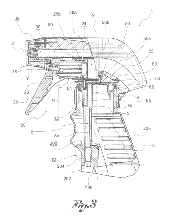
figure 1;
[0011] - figure 3 shows a cross-section view of a dispenser
device according to the present invention, according to a
further embodiment;
[0012] - figure 4 shows an enlargement of the detail IV in
figure 3;
[0013] - figure 5 shows the detail of figure 4, in separate
parts;
[0014] - figure 6 shows an auxiliary body of the device in
figure 3;
[0015] - figure 7 shows a front view of the auxiliary body in
figure 6; and
[0016] - figure 8 shows a cross-section view of the auxiliary
body in figure 7, taken along the section line
CA 2810638 2017-09-28
CA 02810638 2013-03-06
WO 2012/035445
PCT/1B2011/051496
3
=
VIII in figure 7.
[00U] With reference to the appended drawings, reference
numeral I globally denotes a manually operated dispenser
=
device of a liquid.
[0018] The dispenser device comprises a container, C to
contain the liquid to be dispensed, comprising a neck N
made by an annular wall W around a container axis X,
which defines by means of an annular rim B, a container
aperture A for access to the inside of the same.
[0019] The dispenser device 1 comprises a dispenser head 20
attached to the container C to manually aspirate the
liquid from the container and dispense it to the outside.
[0020] The head 20 is pre-assembled and in general sent for
filling of the container separately from it. After
filling the container with liquid, the head is coupled to
the container.
[0021]The head 20 further comprises an auxiliary body 2
attached to the neck N of the container C, at the
aperture A of the same, to close it peripherally forming
a seal.
[0022] In particular, the auxiliary body 2 comprises a main
portion 4, inserted through the aperture A in the neck N,
provided with a main surface 4a which remains external, .
==
and an annular. collar 6, overlapping the annular rim B of
the 'neck N, for example folded so as to straddle said
CA 02810638 2013-03-06
WO 2012/035445
PCT/1B2011/051496
4
annular rim B.
[0023] Preferably, the auxiliary body 2 has, on the outer
side, an annular groove 4b which surrounds the main
surface 4a.
[0024]The auxiliary body 2 has a primary liquid aspiration
duct 8 extending along the container axis X, coaxial to
said container axis X.
[0025]In one embodiment variation, the primary liquid
aspiration duct 8 is eccentric to the container axis X,
that is radially distanced from it.
[0026]The primary liquid aspiration duct 8 passes through
the thickness of the main portion 4, placing the
compartment inside the container in communication with
the main surface 4a.
[0027]In particular, preferably, the primary liquid
aspiration duct 8 is defined through a first tube 10,
coaxial to the container axis X.
[0028] Preferably, a flexible or rigid suction tube is
connectable to the tube 10, which extends as far as the
bottom of the container, to suck up the liquid.
[0029] Moreover, the auxiliary body 2 has a primary air
aspiration duct 12, radially distanced from the primary
liquid aspiration duct 8, passing through the thickness
of the main portion 4, to place the outer environment or
main surface 4a in communication with the compartment
CA 02810638 2013-03-06
WO 2012/035445
PCT/1B2011/051496
inside the container.
[0030] In= particular, preferably, the primary air
aspiration duct 12 is defined through a second tube 14,
radially distanced from the first tube 10.
[0031] Moreover, the head 20 comprises a frame 22 to
support the other components and form some passages for
the liquid. The auxiliary body 2 is attached to the frame
22.
[0032] The frame 22 has a pressure chamber 24, annularly
defined by a chamber wall 25, extending along a pressure
axis Y, preferably incident to the container axis X, for
example orthogonally.
[0033] The head 20 comprises a piston 26, sliding in the
pressure chamber 24 so as to be airtight along the
pressure axis Y, between a rest position, wherein the
volume of the pressure chamber 24 is maximum, and a limit
dispensing'position, wherein the volume of the pressure
chamber 24 is minimal, passing through intermediate
dispensing positions.
[0034] Preferably, the piston 26 comprises a head seal 26a
and a tail seal 26b, distanced from the head seal along
the pressure axis Y, for tightness between the piston and
the chamber wall 25 in which it slides.
[0035] The head 20 further comprises manual actuation
devices suitable to move the piston 26 manually in the
CA 02810638 2013-03-06
WO 2012/035445
PCT/1B2011/051496
6
pressure chamber 24.
[0036] Preferably, the actuation means comprise a trigger
28, suitable to act on the piston 26, for example
anchored to it, and engaged with the frame 22, for
example hinged so as to rotate with it or sliding in
translation on it.
[0037] Preferably, moreover, the head 20 comprises elastic
return means able to permanently influence the piston 26
or trigger 28 to return the piston 26 to the rest
position.
[0038] The frame 22 further presents a dispenser duct 30
extending along a dispensing axis Z, between a distal
extremity 32, at the aperture towards the outside, and an
opposite proximal extremity 34.
[0039] Preferably, the pressure axis Y is parallel and
separate from the dispenser axis Z.
[0040] The head 20 further comprises, preferably, a nozzle
38, attached to the distal extremity 32 of the dispenser
duct 30, to enable dispensing of the liquid in the
desired manner.
[0041]The pressure chamber 24 is suitable for being placed
in fluidic communication with the dispenser duct 30.
[0042] In particular, the head 20 comprises valve dispenser
means suitable for allowing the transit of liquid from
the pressure chamber 24 to the dispenser duct 30 when,
CA 02810638 2013-03-06
WO 2012/035445 PCT/1B2011/051496
7
during the dispensing phase, the piston 26 moves from the
rest position towards the dispenser limit position, and
the liquid exceeds a predefined pressure threshold.
[0043] For example, the valve dispenser means comprise an
elastically deformable diaphragm 40, attached to the
frame 22.
[0044] Moreover, the frame 22 has a secondary liquid
aspiration duct 50, which co-operates in the connection
of the pressure chamber 24 with the compartment inside
the container.
[0045] Preferably, the secondary liquid aspiration duct 50
comprises an axial section 50a, extending parallel to the
container axis X, and a radial section 50b, extending
parallel to the pressure axis Y of the pressure chamber
24. Following the movement of the liquid aspirated from
the container towards the pressure chamber, the axial '
section 50a is upstream of the radial section 50b.
[0046] Moreover, the head 20 comprises valve dispenser
means suitable for allowing the transit of liquid from
the secondary aspiration duct 50 towards the pressure
chamber 24 when, during a return phase, the piston 26
moves towards the rest position from the dispenser limit
position, and prevents transit of the liquid from the
pressure chamber 24 towards the secondary liquid
aspiration duct 50 during said dispensing phase.
CA 02810638 2013-03-06
WO 2012/035445
PCT/1B2011/051496
8
[0047] Preferably, said valve aspiration means comprise an
elastically deformable aspiration diaphragm 52, fitted
between the pressure chamber 24 and the secondary liquid
aspiration duct 50.
[0048]The frame 22 comprises a support plate 60, by means
of which the frame 22 engages with the auxiliary body 2.
[0049]The plate 60 has a functional surface 62 on the
outside, which the secondary liquid aspiration duct 50
comes out on, in a radially distanced position from the
container axis X that is at least partially misaligned
from the primary liquid aspiration duct 8.
[0050] Preferably the secondary liquid aspiration duct 50,
and in particular the axial section 50a of the same, is
on the opposite side to the secondary air aspiration duct
72 in relation to the container axis X.
[0051]When the head 20 is attached to the container, the
functional surface 62 of the frame 22 is axially
distanced from the main surface 4a of the auxiliary body
2, so that a joining compartment or duct 64 is formed
between these, which connects the main liquid aspiration
duct 8 of the auxiliary body 2 with the secondary liquid
aspiration duct 50 of the frame 22.
[0052]The primary liquid aspiration duct 8, the joining
compartment 64 and the secondary liquid aspiration duct
50 thereby form a liquid aspiration passage which places
CA 02810638 2013-03-06
WO 2012/035445
PCT/IB2011/051496
9
the compartment inside the container in communication
with the pressure chamber 24 of the head 20.
[0053] Moreover, preferably, the frame 22 comprises an
annular lip 66, projecting in the direction of the
container axis X from the functional surface 62 of the
plate 60, inserted in the groove 4b of the auxiliary body
2, to form a seal.
[0054]Moreover, the frame 22 comprises a tubular
aspiration insert 70, projecting from the functional
surface 62 and inserted so as to form a seal in the
aspiration tube 14 of the auxiliary body 2, defining
within it a secondary air aspiration duct 72. The insert
70 therefore crosses the joining compartment 64 destined
for transit of the liquid.
[0055]The primary air aspiration duct 12 and the secondary
air aspiration duct 72 are therefore in communication
with each other and form a separate air aspiration
passage sealed from the liquid aspiration passage.
[0056]In particular, the secondary air aspiration duct 72
comprises an aspiration hole 80 made through the chamber
wall 25.
[0057] Preferably, when the piston 26 is in the rest
position, the hole 80 is separated from the pressure
chamber 24 by the head seal 26a of the piston 26 and is
separated from the outside environment by the tail seal
,
CA 02810638 2013-03-06
WO 2012/035445
PCT/1B2011/051496
26b of the piston 26; when the
piston 26 is in the
dispensing limit position, the hole 80 is in
communication with the outside environment, but is
separated from the pressure chamber 24 by the tail seal
26b (and by the head seal 26a).
[0058] In an initial rest configuration, the piston 26 is
in the rest position, the valve dispenser means are
closed, the valve aspiration means are closed, the air
aspiration passage towards the outside is closed; the
presence of liquid to dispense in the pressure chamber 24
is presumed.
[0059] In the dispensing phase, the piston 26 completes a
dispensing stroke from the rest position to the limit
dispensing position by manual activation of the trigger
28.
[0060] By effect of the liquid in the pressure chamber 24,
the liquid aspiration valve means remain closed,
preventing the backflow of liquid towards the container.
[0061] By effect of the pressurised liquid, the valve
dispenser means open, making the liquid travel from the
pressure chamber 24 to the dispenser duct 30, thereby
enabling dispensing from the nozzle 38.
[0062] When the trigger is released, the elastic return
means move the piston 26 or the trigger 28 from the
=dispensing limit position towards the rest position.
CA 02810638 2013-03-06
WO 2012/035445
PCT/1B2011/051496
11
[0063] In the return phase, the piston 26 performs a return
stroke from the dispensing limit position towards .the
return position.
[0064] The negative pressure which is formed in the
pressure chamber 24 closes the dispenser valve means.
[0065] The negative pressure which is formed in .the
pressure chamber 24 opens the liquid aspiration valve
means and the liquid transits from the compartment inside
the container into the pressure chamber 24, through the
primary liquid aspiration duct 8, the joining compartment
64 and the secondary liquid aspiration duct 50. .
[0066] At least for a part of the return phase, the air
aspiration passage is in communication with the outside
environment, so that the air can be aspirated into the
compartment inside the container.
[0067] The air aspiration passage, and in particular the
secondary air aspiration duct 72,= is fluidically
separated from the liquid aspiration passage, and in
particular from the joining compartment 64, so that there
is no leakage of liquid.
[0068] According to a further embodiment, the container C
Comprises an annular container wall 200 around the
container axis X and an auxiliary liquid aspiration duct
202, made entirely in said lateral wall of the container
C.
CA 02810638 2013-03-06
WO 2012/035445
PCT/1B2011/051496
12
[0069] In other words, the container wall 200 comprises a
portion of functional wall 204, for example positioned
head-on with the container, that is on the side destined
for the liquid to come out, and an auxiliary wall 206, in
one piece with the container wall 200, inside the
container C, which runs along the portion of functional
wall 204, so as to form with it the auxiliary liquid
aspiration duct 202.
[0070] Said duct 202 is open near the bottom of the
container, to aspirate the liquid contained in it.
[0071] Preferably, said duct 202 starts from an engagement
mouth 208, axially distanced from the neck N of the
container C.
[0072] The primary liquid aspiration duct 8, at least
partially eccentric to the container axis X, is suitable
for inserting in the engagement mouth 208 of the
auxiliary liquid aspiration duct 202.
[0073] For example, advantageously, the primary liquid
aspiration duct 8 comprises a first section 8a, which
starts from the main surface 4a, having a first duct axis
proximal to the container axis X and a second section 8b,
adjacent to the first section 8a and terminating in the
engagement mouth 208, distal to the container axis X.
[0074] Preferably, moreover, the primary liquid aspiration
duct 8 comprises, in the terminal part suitable for
CA 02810638 2013-03-06
WO 2012/035445
PCT/1B2011/051496
13
insertion in the engagement mouth 208, a flexible
coupling portion 210, made in a less rigid material than
the material of the remaining part of the primary liquid
aspiration duct 8.
[0075] Preferably, the flexible coupling portion 210 is
made in one piece with the remaining part of the duct 8,
for example by means of a co-moulding process.
[00715] For example, the flexible coupling portion 210 is
made in Ethylene-Vinyl-Acetate (EVA) or in a material
from the group of thermoplastic elastomers (TPE); the
remaining part of the tube is rather made preferably made
from high density polyethylene (PEHD).
[0077] Advantageously, this makes insertion of the duct 8
in the engagement mouth 208 particularly easy.
[0078] Preferably, moreover, the primary liquid aspiration
duct 8 and the secondary liquid aspiration duct 50 are
positioned on diametrically opposite sides to the
container axis X. In particular, for example, the first
section 8a of the primary liquid aspiration duct 8 is
completely contained on one side of the container axis X
and the axial section 50a of the secondary liquid
aspiration duct 50 is completely contained on the other
side.
[0079]Innovatively, the dispenser device according to the
present invention, despite having asymmetric components
CA 02810638 2013-03-06
WO 2012/035445
PCT/1B2011/051496
14
and off-axis ducts, retains considerable assembly
simplicity.
[0080]In particular, advantageously, the head ensures a
good seal with the container, thanks to the interposition
of the auxiliary body between the frame and neck of,the
container, made in particularly suitable material for
forming a seal with the neck of the container.
[0081] Moreover, advantageously, the head ensures a good
internal seal between the frame and auxiliary body, made
in materials suitable for such purpose.
[0082] Advantageously, moreover, the dispenser device
ensures aspiration of the air in the container preventing
the leakage of liquid in said duct.
[0083] According to a further advantageous aspect, the
dispenser device ensures aspiration of the air in the
container preventing liquid from escaping from the air
aspiration passage, for example when the device is
inclined.
[0084] In particular, according to a further advantageous
aspect, the connection system of the head and container
is particularly suitable in the case of containers with
liquid aspiration ducts built-in to the container, for
which the built-in duct is strongly off-axis with the
aspiration duct of the frame and therefore needs an
intermediate fluidic connection structure.
= CA 02810638 2016-04-20
[0085] It is clear that a person skilled in the art may make
modifications to the dispenser device described above so as to
satisfy contingent requirements.