Note: Descriptions are shown in the official language in which they were submitted.
CA 02810682 2017-02-17
WO 2012/033499 PCT/IIS2010/048481
COLUMBARIUM CONSTRUCTION AND SHUTTER MOUNTING SYSTEM
2
3
4
BACKGROUND
6 Stone shutters are removably secured to columbarium structures by a
mounting
7 system that is preferably substantially concealed or substantially hidden
from view so as
8 not to detract from the appearance of the stone and the reverent
atmosphere of the
columbarium. The concealed mounting system must resist corrosion and it must
securely
hold the shutters in position despite extreme temperature swings and countless
freeze-
ti thaw cycles for season-after-season and year-after-year, for decades, if
not centuries. In
12 addition, the mounting system must permit the shutters to be relatively
easily removed
13 and replaced even after years or decades of being exposed to the
elements.
14 US Patent No. 4,6108,711 to Eickhof discloses one type of concealed
shutter
mounting system that meets all of the foregoing challenges. Variations of the
Eickhof
18 '711 concealed shutter mounting system have achieved significant
commercial success in
17 the columbarium industry. However, a simpler and more cost effective
concealed
18 fastener system is needed in view of the recent trend away from using
large 24" x 24"
19 stone panels and toward the use of 8" x 8" individual niche shutters.
The terms "shutter,"
"panel," "slab" and "facing stone" are used interchangeably throughout this
specification.
21 A standard columbarium niche is 8" x 8". Until relatively recently, it
was
22 common to use 24" x 24" stone slabs with false joints cut into the
finish face of the stone
23 slab to simulate nine 8" x 8" individual niche shutters. Each of the
nine 8" x 8" spaces on
24 the large panel is typically engraved with a the name, birth year and
death year of the
deceased person whose urn resides behind that 8" x 8" space. Thus, each time
an urn is
26 to be placed into one of the nine niches, or each time one of the nine
niches is to be
27 engraved, the entire 24" x 24" stone panel has to be removed and then
replaced. A
28 typical 24" x 24" stone panel weighs about sixty pounds. Because of the
potential for
1
CA 02810682 2013-03-06
WO 2012/033499 PCT/US2010/048481
1 misspelling of names or errors in the birth or death dates during each
time the panel is
2 engraved, it is not uncommon to have to discard and replace an entire
panel due to a
3 single mistake made when engraving one of the nine niches. Accordingly,
it should be
4 appreciated that large panels are not only difficult to handle by a
single person due to
their size and weight, but the use of large panels can be expensive if the
panels need to be
6 replaced due to engraving errors.
7 As a result of the foregoing concerns with the use of 24" x 24"
panels, a relatively
8 recent trend in the columbarium industry is to use 8" x 8" individual
niche panels. These
9 smaller panels are easier to handle during initial installation and when
they need to be
subsequently removed for engraving or when placing an urn within the niche. If
there is
11 ever an engraving error, only the single 8" x 8" panel needs to be
replaced instead of the
12 entire 24" x 24" panel. It should be appreciated, however, that when
going from one
13 large panel to nine smaller individual panels, all other things being
equal, the amount of
14 individual hardware pieces required to mount the panels will necessarily
increase as will
the amount of material costs and labor costs associated with the initial
assembly of the
16 panels and the initial mounting of the panels.
17 Accordingly, there is a need in the industry for a universal
concealed mounting
18 system capable of use with virtually any size columbarium shutters, but
which has fewer
19 pieces and is quicker and easier to assemble and install then currently
available mounting
systems in order to reduce material costs and labor costs so that even the use
of smaller
21 individual 8" x 8" shutters is at least as cost effective as using
larger 24" x 24" panels
22 mounted with currently available mounting systems.
23 Heretofore, columbaria structures have been constructed using a
variety of
24 different materials and techniques. For example, some columbarium
structures have been
constructed using cast-in-place or precast concrete to form the niches. Other
26 columbarium structures have been constructed entirely from aluminum
members welded
27 or bolted together to form the niches. While each of these types of
construction may
28 serve the intended purpose, both construction types are costly and time
consuming. U.S.
29 Patent No. 5195,812 to Eickhof (hereinafter "the '812 patent") discloses
a columbarium
2
CA 02810682 2013-03-06
WO 2012/033499 PCT/US2010/048481
1 structure that is comprised of a framework of vertical risers and
horizontal shelves
2 secured together by brackets and tie-rods to form the niches. The '812
patent discloses
3 that the vertical risers are constructed of cement fiberboard and the
plastic shelves are
4 constructed of extruded plastic. The '812 patent discloses that the back
of the niches are
closed off by large cement fiberboard panels secured by rivets or screws to
the back
6 flange of the extruded horizontal shelves. The framework of niches is
then secured to a
7 supporting wall or another bank of niches. The type of framework
construction
8 disclosed in the '812 patent has proven to be very commercially
successful due to the
9 savings in labor, time and materials over previous construction methods
because the
framework is comprised of relatively light weight prefabricated members
designed to
11 easily fit together for quick assembly while still providing a durable
and quality
12 appearance.
13 Some customers, however, viewed the use of plastic shelves as being
of lesser
14 quality and it was also found that the dimension tolerances of the
extruded plastic shelves
could not be satisfactorily controlled, impeding the assembly process. As a
result, as
16 disclosed in co-pending U.S. Patent Application No. 12/476529 to Eickhof
(hereinafter
17 "the '529 application"), the extruded plastic shelves were replaced with
cement
18 fiberboard. While cement fiberboard shelves provide a more high quality
appearance
19 than plastic shelves, they are much heavier and therefore more expensive
to ship and
more difficult to lift and handle. Furthermore, with the use of a cement
fiberboard shelf,
21 both a front rail and a back rail are necessary to support the shelf and
to provide the
22 necessary surface area on which to secure the cement fiberboard to
enclose the back of
23 the niches and to support the stone facing at the front of the niche.
Accordingly, there is
24 a need for a columbarium construction that provides the features and
advantages of the
framework system disclosed in the '812 patent and which provides the higher
quality
26 appearance disclosed in the '529 application, but which is lighter
weight for easier
27 handling, which reduces shipping costs, and which reduces handling and
labor costs for
28 assembly.
29 Furthermore, although the concealed mounting system disclosed in the
'529
application was a significant improvement over previous concealed mounting
systems,
3
CA 02810682 2013-03-06
WO 2012/033499 PCT/US2010/048481
1 the mounting system disclosed in the '529 application did not permit in-
and-out
2 adjustment of the shutters or facing stones. As a result, if there was
even a minor
3 variation in thickness of the facing stones, it was difficult to adjust
the stones in-and-out
4 to provide a smooth or flush wall surface. Furthermore, with the mounting
system of the
'529 application, when a facing stone was removed, unless it was replaced
exactly in the
6 original location the vertical gap between adjacent stones would be
inconsistent and
7 detract from the appearance of the columbarium unless time was taken to
adjust the
8 facing stone to correct the gap or spacing between the adjacent stones.
Additionally,
9 some customers prefer a columbarium structure with a relief pattern in
the facing stones.
Accordingly, it is desirable to provide a concealed mounting system that can
11 accommodate different stone thicknesses and to permit in-and-out
adjustment so the
12 facing stones can be easily placed with the desired relief pattern in
the wall. It is also
13 desirable to provide a mounting system, that will allow the facing
stones to be replaced in
14 the same location so as to ensure spacing between the stones remains
uniform without
having to adjust the stones after they are replaced.
16 DESCRIPTION OF THE DRAWINGS
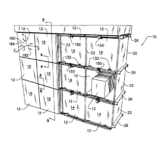
17 FIG. 1 is a perspective view of a columbarium comprising a plurality
of niches,
18 wherein some of the niches are open, some are shown with inner closure
panels disposed
19 over the front opening, and other niches are shown with shutters mounted
utilizing an
embodiment of a concealed mounting system cooperating with an embodiment of
the
21 horizontal member.
22 FIG. 2 is partial side perspective view of the columbarium of FIG. 1
showing a
23 detailed view of the preferred embodiment of the concealed mounting
system and
24 horizontal member.
FIG. 3 is a cross-sectional view of the columbarium of FIG. 1 as viewed along
26 lines 3-3 of FIG. 1.
27 FIG. 4 is an enlarged view of the area circled in FIG. 3 showing in
detail the
28 preferred embodiment of the bottom hanger and swivel socket of the
concealed mounting
4
CA 0 2 8 10 6 8 2 2 0 17 - 0 2 - 17
WO 2012/033499 PCT/US2010/048481
system.
2 FIG. 5 is an enlarged view of the other area circled in FIG. 3
showing in detail the
3 preferred embodiment of the upper clip and upper lock of the concealed
mounting
4 system.
FIG. 6 is a rear perspective view of a shutter illustrating a portion of the
preferred
embodiment of the concealed mounting system secured to the back side of the
shutter.
7 FIG. 7 is an exploded perspective view of the shutter and portion of
the concealed
mounting system of FIG. 6 and illustrating the slots fabricated into the back
side of the
9 shutter to receive the anchors.
to FIG. 8 is a perspective view of a columbarium with an example of a
relief pattern
11 to show how different size facing stones and different thicknesses of
stones can be used
12 with the concealed mounting system of the present invention to create
different mosaics
13 and relief patterns.
14 DESCRIPTION
16 Referring now to the drawings, wherein like reference numerals
designate
16 identical or corresponding parts throughout the several views, FIG. 1 is
a perspective
17 view of a columbarium 10 comprising a plurality of niches 12 which may
hold one or
18 more urns 13. Some of the niches 12 are shown open, some are shown with
inner closure
19 panels 14 disposed over the niche opening, and other niches 12 are shown
with shutters
20 or facing stones 16 secured over the closure panels 14 utilizing a
concealed mounting
21 system 100 as described in detail later.
22 The columbarium 10 preferably comprises a framework 20 of
horizontally
23 spaced, vertical, planar risers 22 and vertically spaced, horizontal
shelves 24. As
24 disclosed in US Patent No. 5,195,812 to Eickhof (hereinafter "the '812
Patent") and in
25 pending U.S. Application No. 12/476529 (hereinafter "the '529
Application"),
26 shelf brackets
26 and tie rods
27 28 (best viewed in FIG. 3) secure the vertical risers 22 and horizontal
shelves 24 in
5
CA 02810682 2013-03-06
WO 2012/033499 PCT/US2010/048481
spaced relation to define a grid of a plurality of niches 12. However, unlike
the systems
2 disclosed in the '812 patent or in the '529 Application, in the
embodiment of the present
3 invention (discussed in greater detail later), the horizontal shelves 24
are preferably
4 comprised of a single horizontal member 200 that includes a front rail
202 and a back
flange 204 joined by a planar web 206 (best viewed in FIG. 3). As discussed in
detail
6 later, the front rail 202 cooperates with the concealed mounting system
100 to adjustably
7 support the shutters or facing stones 16. The back flange 204 provides a
surface to which
8 the back wall 32 is secured by rivets or threaded connectors. It should
be appreciated that
9 the large section modulus of the horizontal member 200 (resulting from
the front rail 202,
back flange 204 and web 206) provides substantial lateral and longitudinal
stability when
11 the framework structure 20 is tied together with the tie rods 28.
12 The horizontal member 200 is preferably fabricated from extruded
aluminum, but
13 may be fabricated from pultruded fiber reinforced polymer ("FRP") or any
other suitably
14 rigid, weather resistant, and dimensionally stable, extrudable or
pultrudable materials.
The dimensions of the horizontal member 200 may vary depending on the desired
size of
16 the niches 12, the span between risers 22, any anticipated static or
dynamic loading
17 conditions, the overall dimensions of the framework 20 and the support
structure (if any)
18 to which the framework 20 is to be secured.
19 As best illustrated in FIGs. 2-5, the front rail 202 of the
horizontal member 200
includes a forwardly projecting flange 208 having a top surface 210 offset a
distance
21 downwardly from the top surface of the web 206. The front rail 202 also
includes a
22 downwardly projecting flange 212. A top channel 214 and a top slot 216
are also formed
23 along the length forwardly projecting flange 208. Referring to FIG. 3,
when two
24 horizontal members 200 are disposed in vertical spaced relation, the top
slot 216 of the
lower horizontal member 200 is vertically aligned with the front face of the
downwardly
26 projecting flange 212 of the upper horizontal member 200 so that the
inner closure panel
27 14 is substantially vertical. As best viewed in FIGs. 4 and 5, a turn
tab 218 is pivotally
28 secured to the downwardly projecting flange 212 by a threaded connector
or rivet 220 to
29 hold the top edge of the inner closure panel 14 in position, while the
bottom edge of the
inner closure panel 14 is received in the top slot 216. To remove the inner
closure panel,
6
CA 0 2 8 10 6 8 2 2 0 17 - 0 2 - 17
WO 2012/033499 PCT/US2010/048481
1 the turn tab 218 is rotated up to free the top edge of the inner closure
allowing the top
2 edge to tilt forwardly so it can be grasped and lifted from the top slot
216 of the lower
3 horizontal member 200.
4 Referring to FIGs. 2-7, the concealed mounting system 100 preferably
includes an
upper clip 102 and at least one, preferably two, lower support hangers 104
secured to the
6 back side of the shutter 16. The upper clip 102 preferably includes an
upwardly curving
hook 106 that receives and is engaged by the upper lock 150 (described in
greater detail
a later). The lower support hangers 104 preferably comprise an L-shaped
bracket 108 with
9 threaded studs 110 threadably received through a threaded apertures 112
in the
rearwardly projecting leg 114 of the L-shaped bracket 108. The upper clip 102
and
11 hangers 104 are preferably fabricated from extruded aluminum or other
suitably rigid,
12 weather resistant and dimensionally stable, extrudable or pultrudable
material.
13 In the preferred embodiment, as best illustrated in FIGs. 4, 5 and 7,
the clip 102
14 and hangers 104 are secured with threaded anchors 120. The heads 122 of
the threaded
anchors are received within inverted T-shaped slots 124 cut into the back side
of the
16 stone such as disclosed in US Patent No. 4,020,610,
17 . The threaded shaft 126 of the anchors 120 project from the
back
18 face of the shutter 16 and are received through apertures 128 in the
clips 102 and hangers
19 104. A nut 130 is threaded onto the projecting threaded shaft 126 and
are preferably
tightened to approximately 95 in-pounds of torque to securely attach the clips
102 and
21 hangers 104 in place and to prevent their rotation.
22 The preferred concealed mounting system 100 further includes at least
one hanger
23 support 132, preferably two, for cooperatively receiving and supporting
the threaded stud
24 110. The hanger support 132 preferably comprises a swivel socket with an
elongated
body 134 having an aperture 136 near one end and a socket or indentation 138
at an
26 opposite end. The swivel socket 132 is slidably positioned along the
front rail 202 of the
27 horizontal member 200 by a threaded lug 140 having a head 142 received
within the top
28 channel 214 of the front rail 202. The shaft 144 of the lug 140 extends
through the top
29 channel 214 and into the aperture 146 of the swivel socket 132 and is
secured by a nut
7
CA 02810682 2013-03-06
WO 2012/033499 PCT/US2010/048481
1 148. By loosening and tightening the nut 148, the swivel socket 132 can
pivot or swivel
2 about the lug 140 and can be slidably, adjustably, fixably positioned
anywhere along the
3 length of the top channel 214 in order to align the socket 138 to receive
the downwardly
4 extending threaded stud 110. By turning the threaded stud 110 clockwise
or
counterclockwise it will cause the shutter 16 to raise or lower, respectively,
relative to the
6 swivel socket 132 and front rail 202 thereby providing vertical
adjustment of the shutter
7 16. Likewise, by loosening and tightening the nut 148 on the lug 140, the
swivel socket
8 132 can pivot inwardly or outwardly relative to the front rail 202
thereby providing in-
and-out or fore-and-aft adjustment at the bottom of the shutter 16.
The concealed mounting system 100 also preferably includes an upper lock 150.
ii The upper lock 150 includes a rearwardly projecting flange 152 having an
elongated slot
12 154. Similar to the swivel sockets 132, the upper lock 150 is slidably
positioned along
13 the front rail 202 of the horizontal member 200 by a threaded lug 140
having a head 142
14 received within the top channel 214 of the front rail 202. The shaft 144
of the lug 140
extends through the top channel 214 and into the elongated slot 154 of the
rearwardly
16 projecting flange 152. By loosening and tightening the nut 148 threaded
over the shaft
17 144 of the lug 140, the upper lock 150 can be positioned inwardly or
outwardly relative
18 to the front rail 202 thereby providing in-and-out or fore-and-aft
adjustment at the top of
19 the shutter. Furthermore, by loosening and tightening the nut 148 on the
lug 140 the
upper lock can be slidably, adjustably, fixably positioned at the desired
location along the
21 channel 214. This lug and nut configuration avoids the need to drill a
hole through the
22 front rail required for the locking screw in the '529 application.
Additionally, because
23 the lugs 140 of the top lock 150 and bottom hanger supports 132 use the
same channel,
24 the front rails has a simpler cross-section and requires less material
than the front rail
disclosed in the '529 application.
26 The preferred upper lock 150 includes a forwardly extending channel
156, and a
27 downwardly extending channel 158. Apertures 160, 162 extend through the
forwardly
28 extending channel 156 and downwardly extending channel 158,
respectively. A locking
29 screw 164 passes through both apertures 160, 162. The locking screw 164
includes a
threaded upper shaft 166 and a rectangular lower shaft 168. The threaded upper
shaft 166
8
CA 02810682 2013-03-06
WO 2012/033499 PCT/US2010/048481
1 is threadably received by a nut 170 disposed within the forwardly
extending channel 156.
2 The nut 170 is larger than the diameter of the apertures 160, 162 such
that the locking
3 screw 164 is vertically supported within the forwardly extending channel
156 by the nut
4 170. The width of the rectangular lower shaft 168 of the locking screw is
preferably only
slightly less than the width between the legs of the downwardly extending
channel 158
6 such that the rectangular lower shaft 168 prevents the locking screw 164
from rotating
7 within the channel 158.
8 As best illustrated in FIG. 2, the nut 170 is accessible for rotation
by an open end
9 wrench 172 (FIG. 2) inserted in the gap 174 between vertically adjacent
shutters 16. It
should be appreciated that because the cooperation of the rectangular lower
shaft 168
ii within the downwardly extending channel 158 prevents the locking screw
164 from
12 rotating. Upon turning the nut 170 clockwise using the wrench 172, the
locking screw
13 164 is caused to move downwardly allowing the end of the rectangular
lower shaft 168
14 to engage the upwardly curving hook 106 of the upper clip 102. Likewise,
by rotating the
nut 170 counter-clockwise using the wrench 172, the locking screw 164 is
caused to
16 move upwardly thereby disengaging the end of the rectangular lower shaft
168 from the
17 upward hook 106 of the clip 102 and allowing the shutter 16 to be easily
removed for
18 access to the niche 12. The end of the rectangular lower shaft 168 is
preferably beveled
19 to better mate with the upwardly curving hook 106.
The in-and-out adjustment capability at the top of the shutter when combined
with
21 the in-and-out adjustment capability at the bottom of the shutter,
allows for easier and
22 faster installation of shutters and better accommodates different
shutter thicknesses,
23 whether due to thickness tolerances or inconsistencies in the stone or
whether different
24 stone thicknesses are being used to create a relief pattern such as
shown in FIG. 8.
Furthermore, it should be appreciated that once the nut 148 is tightened down,
the swivel
26 sockets 132 and the top lock 150 are prevented from pivoting or sliding
horizontally
27 within the top channel 214. Thus, if the facing stone or shutter 16 is
ever removed, when
28 it comes time to replace the shutter, the threaded studs 110 will be
guided to seat in the
29 bottom of the sockets 138 of the swivel socket 132 and the top lock 150
will cooperate to
ensure that the shutter is returned to the exact same position before it was
removed
9
CA 02810682 2013-03-06
WO 2012/033499
PCT/US2010/048481
1 thereby avoiding the tedious task of having to readjust the shutter to
ensure a uniform gap
2 with the adjacent shutters.
3 As shown
in FIG. 1, It should also be appreciated that through the pivotable
4 movement of the swivel sockets 132, and with the centrally positioned
upper lock 150,
the shutter is capable of pivoting about a vertical Y axis as indicated by
arrow 180.
6 Furthermore, with threaded studs 110 received within the swivel sockets
132, and with
7 the curvature of the upper clip cooperating with the upper lock 150, the
shutter is also
8 able to pivot about a horizontal X axis as indicated by arrow 182. Also,
with the
9 independent vertical adjustability of the threaded studs 110 cooperating
with the swivel
sockets, the shutter is also able to pivot about the Z axis as indicated by
arrow 184. Thus,
11 the shutter 16 is capable of being adjustable in three dimensions or
about three axes of
12 rotation, thereby enabling infinite adjustment of the shutters 16 to
ensure uniform gaps
13 are maintained between adjacent shutters for a more pleasing aesthetic
appearance and to
14 ensure the front of adjacent shutters are flush if desired, or as
illustrated in FIG. 8, to
allow adjacent shutters to be moved in or out to create a relief pattern if
desired.
16 As shown in FIG. 8, it should also be appreciated that the concealed
mounting
17 system 100 allows more versatility than current shutter mounting systems
by allowing the
18 upper clips 102 and hangers 104 on the back of the shutters 16 to have
varying positions
19 between adjacent shutters and it allows for the shutters 16 to be placed
anywhere along
the front rail. This versatility will permit different sized niche fronts to
be used along the
21 columbarium wall thereby avoiding the post-office-box look that is often
created when an
22 entire columbarium wall comprises a grid of 8" x 8" shutters. For
example, the mounting
23 system 100 will easily allow 8" x 8" single niche shutters to be
positioned adjacent 8"
24 high x 16" wide shutters or vertical 16" high x 8" wide shutters or 12"
x 12" shutters or
24" x 24" panels as desired. Accordingly, the mounting system 100 will allow
more
26 versatility in the configuration of niche fronts to create
embellishments and introduce
27 more and different types of stone mosaic patterns.
28 The foregoing hardware and components comprising the concealed
locking
29 system are preferably made of corrosion resistant material such as
stainless steel, brass or
CA 02810682 2013-03-06
WO 2012/033499 PCT/US2010/048481
1 aluminum or plated with a corrosion resistant finish and are preferably
galvanically
2 compatible with the other components to which they come into contact to
minimize
3 oxidation or corrosion so they remain capable of supporting the loads
anticipated for the
4 structure and withstanding extreme environmental conditions to which they
may be
subject.
6 It should be appreciated that the concealed mounting system 100 and
cooperating
7 horizontal member 200 may have application outside the internment
industry where a
8 concealed mounting system is desired for security or aesthetic reasons.
For example, the
9 concealed mounting system 100 and cooperating horizontal member 200 may
be used in
building structures that require removable wall panels. Another application
may be for
11 removably securing protective panels over windows of buildings or houses
for protection
12 from hurricanes or high winds. The foregoing mounting system 100 is
equally suitable
13 for fixed wall panels, where, once mounted, there may never be a need to
remove the
14 panel. Other applications may include the commercial sign industry where
a concealed
hardware is desirable to deter vandals and allow easy change-out of signs,
16 advertisements, tenant directories, etc.
17 The foregoing description is presented to enable one of ordinary
skill in the art to
18 make and use the invention and is provided in the context of a patent
application and its
19 requirements. Various modifications to the preferred embodiment of the
apparatus, and
the general principles and features of the system and methods described herein
will be
21 readily apparent to those of skill in the art. Thus, the present
invention is not to be
22 limited to the embodiments of the apparatus, system and methods
described above and
23 illustrated in the drawing figures, but is to be accorded the widest
scope consistent with
24 the spirit and scope of the appended claims.
11