Note: Descriptions are shown in the official language in which they were submitted.
CA 02810934 2013-03-08
METHOD AND DEVICE FOR AUTOMATIC REMOVAL OF CARBON DEPOSITS FROM
FLOW CHANNELS IN "NON-RECOVERY" AND "HEAT RECOVERY" COKE OVENS
[0001] The invention relates to a method for automatic removal of carbon
deposits
from flow channels in "Non-Recovery" and "Heat-Recovery" coke ovens, there
being utilized
one coke oven bank typically comprised of several coke oven chambers arranged
side by
side for cyclical carbonization of coal, and there being used an air dosage
facility operating at
positive pressure in order to remove carbon deposits accumulating in flow
cross-sections of
the oven system by combustion and thereby counteracting a reduction of the
oven
performance rate. The invention also relates to a device by means of which
this method can
be implemented, wherein this device is integrated into the coke oven bank and
at least into
one coke oven chamber, so that carbon deposits can be removed during operation
without
modifying any arrangement.
[0002] Carbonization of coal to obtain coke is often accomplished in coke oven
chambers of the so-called "Non-Recovery" or "Heat Recovery" type which are
distinguished
from conventional coke oven chambers in that the coke oven gas evolving during
coal
carbonization is not captured and recovered but utilized for combustion and
heating. On coal
carbonization in this oven type, the gas evolving during coal carbonization
streams into a gas
space located above the coke cake where partial combustion of the coke oven
gas occurs
with a sub-stoichiometric quantity of air. As a result hereof, the coal or
coke cake is heated
from above. The gas space above the coke cake is also called primary heating
space.
[0003] Partly burnt coking gas from the primary heating space is then passed
via so-
called "downcomer" channels into flue gas channels located under the coke oven
chamber
bottom floor and provided for complete combustion of partially burnt coke oven
gas. These
are supplied with secondary combustion air through secondary air soles
connected to the
atmosphere outside. The gas space under the coke cake is also called secondary
heating
space. In the majority of layouts, the vertically arranged downcomer channels
pointing
downwards in the direction of flow are located in non-frontal side walls of
the coke oven
chambers whereby partially burnt coke oven gas streams into the flue gas
channels.
[0004] An embodiment for coke oven chambers comprised of downcomer channels in
side walls is described in WO 2009077082 A2. This invention relates to a
device for feeding
and controlling of secondary air from secondary air ducts into flue gas
channels of horizontal
CA 02810934 2013-03-08
coke oven chambers. The flue gas channels are located underneath the coke oven
chamber
floor on which coal carbonization is realized. Controlling elements which can
precisely control
the air flow into the flue gas channels are mounted in the connecting channels
between the
flue gas channels and secondary air ducts which serve for the supply of
secondary air. The
coke oven chamber is comprised of so-called "downcomer" channels for discharge
of
partially burnt gases from the carbonization process which are integrated in
the lateral coke
oven chamber wall, these "downcomer" channels connecting the coke oven chamber
interior
with the flue gas channels.
[0005] In most layouts, the number of downcomer channels in one coke oven
chamber wall amounts up to 12, so a total of 24 downcomer channels can be
provided per
oven. The downcomer channels are downwards directed and in the majority of
layouts, they
are arranged in the walls of coke oven chambers because two walls each
laterally enclose
one coke oven chamber. In the upper section of a downcomer channel, the flow
cross-
section can be altered by means of an adjusting element, thus it is possible
to adjust the
effluent gas volume stream from a channel in longitudinal oven direction.
[0006] Partially burnt coke oven gas is composed of gas components, i.e.
hydrogen,
carbon monoxide, water, methane as well as, though in lesser portions, ethane,
ethene,
propane, propene and higher-grade hydrocarbons, for example benzene, toluene,
xylene.
Thus it contains volatile compounds which may condensate or pyrolyse in the
downcomer
channels and which lead to non-desired carbon deposits. Carbon deposits thus
formed are
composed of tar-laden, soot-forming compounds, and more particularly of
graphite, and in
the course of operating time these deposits may build-up in substantial
quantities. In
particular, these deposits accumulate in the downcomer channels in case
temperatures in
these channels are too low and if no further combustion air is admitted.
Thereby, these
deposits constrain or block the flow cross-sections of the downcomer channels.
[0007] US 6187148 B1 describes a valve for a Non-Recovery coke oven through
which the gas pressure in the interior of a coke oven chamber can be better
controlled and
whereby a supply of air into the downcomer channels is feasible. The valve has
a rotating
plug with a beveled end which progressively connects or disconnects the
interior cavity of a
coke oven chamber with the downcomer channel in order to control and regulate
the gas
pressure in the oven interior. By controlling the gas pressure, the volume of
combustion air
can be controlled as a function of the temperature gradients admitted into the
oven. The
2
CA 02810934 2013-03-08
combustion of a majority of the coal gas in the secondary heating spaces below
the coke
oven chamber, depending on the valve aperture degree, creates a thermal
gradient through
the coke oven chamber floor whereby coke quality is substantially improved.
This publication
does not describe the formation of deposits due to the pyrolysis of coke oven
gas.
[0008] Owing to a combination of a low partial pressure of oxygen and a low
temperature, these cracked hydrocarbon compounds preferably deposit at the
entrance
cross-sections or within the downcomer channels directed downwardly into the
lower oven,
for example in form of elementary carbon, graphite, tar, soot or similar
compounds. Carbon-
laden deposits pose a noticeable factor of interference for the operation of
coke oven
chambers. For example, such deposits constrain gas-conducting facilities so
that the flow of
gas for heating is slowed down or even prevented.
[0009] This problem has hitherto been solved virtually by feeding compressed
air
periodically into the downcomer channels, depending on the visual appearance
of oven
emissions and depending on the estimated oven performance rate, so that carbon
deposits
are removed from the cross-section by way of a compressed-air pulse. For this
purpose, the
lockable downcomer channel inspection ports arranged on the oven top are
utilized to ensure
access to the channels located underneath when being in open status. To clean
these
channels, operators manually blow compressed-air through a compressed-air
lance into the
inspection port for a certain period of time. Through the introduced
compressed-air, carbon
deposits in the further course of flow are burnt with the free OH radicals
contained in air. The
supply with compressed-air is ensured, for example, by way of a mobile
compressor.
[0010] Though this manual procedure removes carbon deposits, it is liable to
failures,
because in a status when the oven doors are closed the entrance cross-section
of the
downcomer channels cannot be visually inspected during operation from the oven
top. The
concurrently reduced process velocity in turn frequently entails delays in the
operational
sequencing.
[0011] A permanent supply of air into the downcomer channels of the downwardly
directed lateral chamber walls already leads to a complete combustion of the
partially burnt
crude gases and on account of the reduced heating performance associated
therewith it is
non-desired in flue gas channels further downstream underneath the oven
chamber. As the
downcomer channels are constrained or blocked, the negative pressure in the
oven chamber
above the coal is reduced or it may even happen that a positive pressure is
developed. With
3
CA 02810934 2013-03-08
a reduction of the negative pressure, the aspirated portion of air is reduced,
and with a
positive pressure, the required primary combustion air can no longer stream
into the oven
chamber. In this case, released crude gas escapes from primary air opening
ports in the
oven top and oven door, thereby causing a substantial ecological burden.
Therefore,
possibilities are searched for to either avoid or periodically remove such
deposits. However,
a visual monitoring is non-desired for practical and economic considerations.
[0012] Carbonization of coal according to the õNon-Recovery" or õHeat
Recovery" ¨
principle follows a distinct coking cycle in the course of which distinct
values of temperature
and pressure prevail at the relevant spots of a coke oven chamber. During coal
carbonization, a certain amount of coal is charged at ambient temperature into
the oven
chamber to be charged and operated sub-stoichiometrically above the oven sole.
Owing to
this circumstance, a temperature drop which can be documented by thermocouples
usually
arranged in the oven chamber vault area initially occurs in this oven chamber.
[0013] In normal operation, after the charging procedure within a time
interval
of t / TEnd = 0 to 0.15, the temperature drop in an oven chamber is
characterized in that a
temperature minimum of the oven chamber temperature ranges between 800 C and
1150 C, depending on the oven type. The ratio 'T I TEnd corresponds to the
standardized
operating time of the oven. Starting from an initial temperature level of
approx. 1000 C to
1450 C at the moment of charging the oven (t I TEnd = 0), the temperature in
the oven
chamber, depending on the oven type, falls shortly by approx. 200 C to 350
C. During the
subsequent time interval / TEnd = 0.15 to 1.0, the oven chamber temperature
again comes
close to the initital temperature level.
[0014] DE 102006004669 Al teaches a coking oven in flat construction style, a
so-
called non-recovery or heat-recovery coking oven which is comprised at least
of a measuring
device to measure the concentration of gas constituents of a coke oven
chamber, coke oven
sole and/or waste gas flue, and in which the optimal feed of primary and/or
secondary air is
determined and controlled via a process computer on the basis of these data.
The invention
also covers a coal carbonization process utilizing such a coking oven. The
invention teaches
the application of measuring parameters for automated control of the feed of
combustion air,
but it does not describe the removal of carbonaceous deposits with the
peculiarities of this
task.
4
CA 02810934 2013-03-08
[0015] US 4124450 A describes a method for reducing the quantity of primary
air fed
into a coke oven chamber throughout the coking period by keeping the quantity
of heated
secondary air for the combustion of the partly burnt coking gas in the lateral
downcomer
channels such that a temperature of 1200 F to 2400 F is set in the lateral
downcomer
channels, and a temperature of 1800 F to 2700 F is set in the secondary air
soles lying
below the coke oven chamber, wherein, by further combustion of incompletely
burnt coking
gas from the downcomer channels, in that the coking continues from the tip to
the bottom
floor and to the sides of the coke cake, the remaining incompletely burnt
coking gas is burnt
in a lateral combustion chamber charged with bricks at a temperature of at
least 1600 F, and
the effluent gas is removed in an effluent gas shaft at a negative pressure in
a water column
of between 3.8 and 4.3 mm.
[0016] WO 2006128612 Al describes a device for the combustion of coking gas in
a
coking chamber of a coke oven of the "Non-Recovery" type or "Heat-Recovery"
type, wherein
a multiplicity of entrance openings for primary air are arranged in the top of
each oven
chamber in such a manner that the coking gas which forms during the coking is
brought into
contact uniformly with the desired quantity of primary air for the partial
combustion of the
coking gas, and these entrance openings for primary air above the oven for
each oven
chamber are combined separately by an air feed system, and the air feed
systems of the
individual oven chambers are connected to an air feed system common to many
oven
chambers, and a control member for changing the quantity of primary air over
the
carbonization time is provided in each case between the common air feed system
and the air
feed systems for the individual oven chambers.
[0017] DE 3701875 Al describes a method for producing coke in a
regeneratorless coke
oven having a coking chamber, in which the coal is heated with a gas line
leading to a
heating flue below the coking chamber, while a negative pressure is maintained
in the coking
chamber, and wherein air is introduced into the coking chamber in such a
quantity that a
reducing atmosphere is maintained not only in the coking chamber but also in
the heating
flue, wherein furthermore the hot combustion gases still containing burnable
substances are
conducted from the heating flue into an effluent gas combustion chamber, in
which the
burnable substances are burnt with excess air at a temperature which reduces
the formation
of nitrogen oxides formed from nitrogen oxide constituents present in the
combustion gases
to a minimum, and then desulfurization and heat recovery are carried out.
5
CA 02810934 2013-03-08
[0018] The pressure in a coke oven chamber also varies in the course of the
coke
making process. "Non-recovery and heat-recovery" coke ovens operate in
negative pressure
mode, whereof an emission-friendly appearance is derived for this oven type.
The level of the
negative pressure in the chambers is usually adjusted and set through a
suction blower or by
exploiting the natural draft of a chimney so as to make a sufficient stream of
air volume
available for the combustion of the maximal crude gas volume stream escaping
during the
initial phase of coal carbonization in order to avoid flame-off losses and
emissions through
primary air opening ports and oven doors. Negative pressures in the oven
chamber above
the coal cake may range between -10 Pa and -100 Pa.
[0019] Thus there are indicators on the basis of which a periodical removal of
carbonaceous coverings can be effected. Now, therefore, it is the object to
perform a
removal of carbonaceous coverings at suitable spots inside a coke oven chamber
based on
measured values for pressure and temperature. The removal of carbonaceous
coverings is
to be performed in the simplest possible manner in order to be able to perform
a removal of
these coverings without shutting down the coke oven chamber or even in running
operation.
[0020] The present invention solves this task by providing for a method
according to
which compressed air is periodically conducted into the downcomer channels
depending on
at least one measuring parameter so that carbon deposits accumulating therein
are
removable by an injection of compressed air blown into the downcomer channel.
Removal of
coverings is accomplished by way of combustion in such a manner that the
carbonaceous
coverings react with the free OH radicals as well as with the oxygen of the
gas introduced
and that an additional suction and cleaning effect is achieved by the inlet
pulse of
compressed air. Injection of compressed air is performed with advantage
through the
inspection ports of the downcomer channels because these are easily accessible
and
because a retrofit is readily possible.
[0021] Control of air injection, for example, can be accomplished via a
measurement of
pressure at any spots of the coke oven chamber. However, the control of air
injection, for
example, can also be accomplished via a measurement of temperature at any
spots of the
coke oven chamber. The introduced compressed air contains the oxygen required
to burn-off
the coverings. A gas enriched with oxygen may also be utilized to implement
the present
invention.
6
CA 02810934 2013-03-08
[0022] The present invention makes it possible to remove carbonaceous
coverings
during operation without requiring an interruption of operation or dismantling
of a coke oven
chamber. Air or oxygen-laden gas is conducted with the desired approach
through
measuring signals or upon expiry of a determined time interval into the
downcomer channels
so that a temporal introduction of oxygen-laden gas is effected. A partial
cooling-down of the
downcomer channels involved by an excessive or uncontrolled supply of oxygen-
laden gas
and entailing possible damage to a coke oven chamber is thus avoided.
[0023] Claim is laid in particular to a method for automatic removal of
carbon deposits
from flow channels in "Non-Recovery" and "Heat Recovery" coke ovens and the
entrance
openings of the downcomer cross section thereof which are on the coke chamber
side,
wherein. a coke oven bank comprised of several coke oven chambers each
comprised
of two lateral coke oven chamber walls and downcomer channels arranged
therein is supplied with compressed air through a compressed air mains,
and which is characterized in that
= a partial stream of compressed air is branched off into at least one coke
oven
chamber and streams into the downcomer channels and can be shut off, and
= the compressed air is fed via a pipe end into the downcomer channels,
which
pipe end is arranged such that the air streams onto the spots where
empirically the majority of deposits accumulate, and
= this partial stream of compressed air, depending on at least one measuring
parameter for pressure or temperature, is conducted into at least one
downcomer channel so that carbon deposits accumulating therein are
removable by a blow of compressed air injected into the downcomer channel.
[0024] This measuring parameter, for example, is a pressure parameter which
is
measured at least at one spot in the coke oven. It is then related to an
already known design
value or to another measurable pressure value. As a rule, one or two
individual pressure
parameters are thus measured. For example, the pressure parameter is a
pressure
differential measured in the combustion chambers below and above the coal and
coke cake,
i.e. between the primary heating space and the flue gas channels underneath
the coke oven
chamber and which amount to Ap > 30 Pa to release and trigger the blow of
compressed air
injection. The pressure parameter may be a pressure differential measured
between the gas
7
CA 02810934 2013-03-08
space of a coke oven chamber, the primary heating space, and the ambient
atmosphere, and
which amounts to -70 Pa < Ap < 40 Pa to release and trigger the blow of
compressed air
injection.
[0025] In case the downcomer channels are blocked due to a clogging upstream,
then
the pressure differential between both combustion chambers, i.e. between the
primary
heating space and the secondary heating space, empirically rise to values of
AP > 30. Due to
the clogging, the secondary combustion process in the secondary air soles
lacks the partially
burnt coking gas. As a consequence, the coal charge is solely heated from
above, i.e. by the
heat from the primary combustion process This leads to a reduced process
velocity which
empirically results in a reduction of the oven performance rate.
[0026] The measuring parameter may also be a temperature parameter which is
measured at least at one spot in the coke oven. This temperature parameter,
for example, is
the temperature measured in the gas space above the coke cake and which
exceeds
T = 1100 C to release and trigger the blow of compressed-air injection.
[0027] The compressed air is for example a normal, non-dried air with an
atmospheric
composition. It is brought through a compressor to a pressure level that is
suitable for
introduction or injection into the inspection ports of the downcomer channels.
However, the
compressed air may also be air which is enriched with oxygen. In another
embodiment of the
present invention, the compressed air may also be replaced with pure oxygen.
For better
execution, the compressed air may also be enriched with combustion-inert
gases. Hence, the
compressed air may also be enriched with nitrogen or waste gas branched off
from the
combustion process. The medium may also be pure oxygen. Finally, the
compressed air may
be air which is mixed with the partially or completely burnt waste gas of the
coke oven
chamber. The medium is typically supplied at a positive pressure of 0.1 to 10
bar. The
medium may be dried or non-dried.
[0028] To release and trigger the compressed air blow, the measuring values of
the
probes are advantageously picked-up, evaluated and controlled by a digital
computer. To
implement the present invention, it is already sufficient if the measuring
value of at least one
pressure or temperature parameter is picked-up, evaluated and controlled by a
digital
computer so that this computer depending on the measuring values turns on at
least one
blow of compressed air into an ancillary piping and the associated downcomer
channels. But
the computer may also turn on at least one blow of compressed air injection
into a
8
CA 02810934 2013-03-08
distribution mains and the associated downcomer channel depending on the
measuring
values.
[0029] In a further embodiment of the invention, a plurality of measured
values are
determined, such that, for example, a combined measurement and evaluation of
temperature
and pressure measuring signals is performed, and the partial stream of
compressed air is
periodically conducted into at least one downcomer channel depending on at
least two
measuring parameters.
[0030] It is also feasible to effect a periodical introduction of compressed
air based upon
empirical values, with the result that the measuring value represents an
empirical
determination of a time interval according to which this partial stream of
compressed air is
periodically conducted into at least one downcomer channel. As an example, the
empirical
values can be determined by preceding measurements of at least one measuring
parameter
of a pressure or temperature value.
[0031] A removal of carbonaceous coverings can be performed at each downcomer
channel of all coke oven chambers. But a removal of carbonaceous coverings can
also be
performed at an individual downcomer of all coke oven chambers, at each
downcomer of one
coke oven bank only, or at each individual downcomer of just one coke oven
bank. It is also
conceivable to effect the removal of the carbonaceous coverings at further
spots of the coke
oven chamber, although the downcomer channels represent the preferred place of
applying
the present invention. To this end, a pipe end is arranged in such a way that,
depending on
at least one measuring parameter of a pressure or temperature value, the
partial stream of
compressed air streams onto the spots where empirically the majority of
deposits
accumulate.
[0032] Due to the large geometrical distance of several meters to the
relevant
downcomer channels located downstream, a removal of carbonaceous coverings by
means
of a prior art controlled elevated primary volume stream into the coke oven
chamber yields
no cleaning effect. For ovens with air supply through the top, this is
reasoned by the fact that
the primary air flow streaming through the oven top initially enters in normal
direction into the
coke oven chamber, said air stream being vertically directed downwards and
striking there
upon the coal cake surface. On this way further downwards, the oxygen
concentration
continuously decreases owing to combustion processes, and the residual oxygen
concentration resting at the coal cake surface finally is so small that it
does not cause any
9
CA 02810934 2013-03-08
effects there in terms of combustion and removal of deposits due to the large
distance to the
downcomer channels.
[0033] A disproportional increase in primary air volume is not possible
because the
process requires sub-stoichiometrical conditions in the combustion chamber
above the
charge.
[0034] Claim is also laid to a device by way of which the inventive method can
be
implemented. Claim is laid in particular to a device in a coke oven chamber
for automatic
removal of carbon deposits from flow channels in "Non-Recovery" and "Heat
Recovery" coke
ovens or the entrance openings of the downcomer cross section thereof which
are on the
coke chamber side, the said device comprised of
= a compressed-air mains installed on the oven top of a coke oven bank built-
up
of several coke oven chambers and connecting the coke oven chambers in
transverse direction,
and which is characterized in that
= the compressed-air mains on the top is comprised of at least one branch
which terminates in its further course into a pipe which in one downcomer
channel in a coke oven chamber is comprised of a pipe end to emit
compressed air, and
= the pipe end is arranged in such a way that the air streams onto the spots
where empirically the majority of deposits accumulate, and at least one
measuring probe for pressure or temperature is arranged at at least one spot
in the coke oven, and
= the latter has a digital computer, which picks up, evaluates and controls
the
control values from at least one pressure sensor or one thermocouple, such
that at least one blow of compressed air into the ancillary piping and into at
least one downcomer channel is turned on by this computer depending on the
measured values.
[0035] For example, the compressed air can be furnished by a compressor. It is
then fed
into a compressed air main. With advantage it extends transversely along the
coke oven
bank. This can be arranged at the level of the top of the coke oven bank. But
for example,
this can also be arranged at the level of service platforms of the oven sole
located laterally at
10
CA 02810934 2013-03-08
the oven front sides of the coke oven bank. Moreover, an arrangement of this
line at the level
of the ground floor is also conceivable.
[0036] The piping on the top of the coke oven bank is then comprised of a
branch which
terminates in its further course into an ancillary pipe extending in
longitudinal oven direction
from the pusher side to the coke side of the oven, and from which at least
another piping
branches off in the further course, said piping terminating into a pipe end
which is suitable to
emit compressed air in a downcomer channel.
[0037] To this effect, each coke oven chamber of a coke oven bank may have a
branch
at the transversely extending compressed air mains, said branch then leading
in another
branch into each downcomer of the coke oven chamber wall. However, it is also
feasible
that only one coke oven chamber has a branch from which all downcomer channels
are
supplied with compressed air in further branches. Furthermore, it is also
feasible that each
coke oven chamber has a branch at the transversely extending compressed air
mains,
whereby only one downcomer channel is furnished with compressed air. Finally
it is feasible
that only one piping on the top of the coke oven bank has a branch which in
its further course
terminates in an ancillary piping extending in longitudinal oven direction
from pusher side to
coke side of the oven, and from which only another distribution mains branches
off in the
further course of the flow route which terminates in a pipe end that is
suitable to emit
compressed air in a downcomer channel.
[0038] In a simple embodiment, it is also conceivable that a pipe end suitable
to emit
compressed air terminates in each downcomer channel of each coke oven chamber
of a
coke oven chamber bank.
[0039] In an embodiment of the inventive method, at least one pipe end has a
built-on
nozzle jet attachment which is suitable to eject a compressed air blow. In an
advantageous
layout, the outlet openings of the nozzle jet can be so configured that the
compressed air
streams at an angle to the vertical line greater than 00 into the cross-
section of the
downcomer aperture. In another embodiment of the inventive method, at least
one pipe end
is horizontally angled. As a result hereof, the pipe end which is suitable to
eject a
compressed air bow can be pointed to the entrance opening of the downcomer
cross-
section. In another embodiment, the outlet opening of the pipe end can be
slotted,
rectangular, annular or circular as well as include a combination of several
outlet shapes of
these. The pipe shapes or configurations for pipe ends as described
hereinabove can be
11
CA 02810934 2013-03-08
implemented at just one pipe or pipe end, but also at an arbitrary number of
pipes or pipe
ends.
[0040] On account of the high temperatures in the downcomer channel which
range
between 950 and 1500 C, the pipe end is made from any material that should be
resistant to
heat. In exemplary configurations, the pipe end is made from a heatproof iron
material, a
ceramic silica material, or a corundum material. Preferably this material is
selected from the
group of heat-resistant steels or refractory ceramic construction materials.
Out of this group
of construction materials, those materials especially suitable are, for
example, materials
especially rich in alumina as well as highly burnt materials based on the raw
material
corundum with A1203-portions ranging between 50-94%, SiO2-portions ranging
between 1.5-
46%, Cr2O3-portions less than 29 %, Fe2O3-portions less than 1.6% and ZrO2-
portions less
than 32%, because these materials are characterized by a high temperature of
application
over 1500 C.
[0041] To control the stream of compressed air into an ancillary piping, the
ancillary
piping is comprised of an automatable valve cock element to serve as shutoff
device to
control the stream of compressed air. The ancillary piping may also be
comprised of an
automatable slide gate element to control and regulate the compressed air
flow. The same
holds for the pipe ends with our without a built-on nozzle jet attachment. To
control the blow
of injected compressed air, at least one pipe end with or without a built-on
nozzle attachment
may be comprised of an automatable valve cock element to control and regulate
the flow of
compressed air. But it is also feasible to choose an automatable slide gate
element to control
and regulate the flow of compressed air. Finally, the control of compressed
air can be
executed by any arbitrary control and/or regulating device.
[0042] All the shutoff devices which serve to control and regulate the
compressed air
flow can be actuated, for example, electrically, hydraulically or by
compressed air. In an
embodiment of the present invention, the element to control and regulate the
compressed air
flow is actuated hydraulically. In another embodiment of the present
invention, the element to
control and regulate the compressed air flow is actuated electrically. In
another embodiment
of the present invention, the element to control and regulate the compressed
air flow is
actuated pneumatically.
[0043] The arrangement of measured value probes on the oven top, for example,
is
taken in such a manner that pressure measuring probes for pressure measurement
are
12
CA 02810934 2013-03-08
conducted through the inspection ports into the downcomer channels of the coke
oven
chamber to be liberated from carbon deposits. But these can also be conducted
into the
primary heating space. For example, 1 to 24 pressure measuring probes for
pressure
measurement are conducted through the inspection ports into the downcomer
channels of
the coke oven chambers to be liberated from carbon deposits. However, for
pressure
measurement, it is also possible to conduct 1 to 3 pressure measuring probes
through the
oven top of the coke oven chamber to be liberated from carbon deposits. It is
also feasible to
conduct 1 to 2 pressure measuring probes for pressure measurement laterally
through the
oven chamber doors of the coke oven chamber to be liberated from carbon
deposits. Finally,
it is also feasible to conduct 1 to 4 pressure measuring probes for pressure
measurement
laterally through the front walls of the oven located above the coke oven
chamber door and
covering the primary heating space. In this manner, a comparative signal is
available which
takes a temperature or pressure measuring value at one spot located in the
upper section of
the coke oven chamber and connected with the primary heating space.
[0044] The arrangement of the other measuring value probes, for example, is
done in
such a manner that 1 to 4 pressure measuring probes for pressure measurement
are
conducted through the lateral front walls of the oven chamber located under
the coke oven
chamber door and covering the secondary heating space or into the secondary
air sole. For
pressure measurement, it is also feasible to conduct 1 to 8 pressure measuring
probes
through the lateral front walls of the oven chamber located under the coke
oven chamber
door and covering the secondary heating space or into the secondary air sole.
It is also
possible to arrange 1 to 2 pressure measuring probes for pressure measurement
in the
connecting channels between the secondary heating space under the coal cake
and the
waste gas collecting duct of the coke oven bank. It is furthermore possible to
arrange 1 to 2
pressure measuring probes for pressure measurement in the waste gas collecting
duct
extending transversely to the coke oven bank on the oven top. It is also
possible to arrange 1
to 2 pressure measuring probes for pressure measurement in the waste gas
collecting duct
extending transversely to the coke oven bank under the coke oven chamber
doors. The
figures indicated hereinabove should be understood as exemplary
configurations, with it
being possible to arrange individual or several pressure measuring probes at
different
positions, too.
13
CA 02810934 2013-03-08
[0045] Thus, the pressure measurements can also be taken in the connecting
channels
between the secondary heating chamber under the coal cake and the waste gas
collecting
duct of the coke oven bank. In one embodiment, there is an upwardly directed
stream in
these channels because the waste gas collecting duct is arranged on the oven
top. In this
form, they are therefore also designated as "uptake" channels and they are
also arranged in
the lateral coke oven walls, though between the downcomer channels. By
arranging pressure
measuring probes in the gas flow upstream and downstream of the deposits
impeding proper
flow through, it is then possible to determine a pressure differential as a
measured value.
[0046] To serve as control signals, it is also feasible to determine
temperature
measuring values. With the coke oven chamber to be liberated from carbon
deposits, at least
one thermocouple is conducted in the vault crest of the coke oven chamber to
be liberated
from carbon deposits through the oven top or through the lateral oven doors
above the coke
cake. Furthermore, at least one thermocouple can be conducted into the gas
space above
the coke cake through the coke oven chamber doors of the coke oven chamber to
be
liberated from carbon deposits. It is also possible to conduct at least one
thermocouple
through the inspection ports into the downcomer channels of the coke oven
chamber to be
liberated from carbon deposits. Since no temperature differential versus
another measuring
value is needed to take-up the temperature measuring values, the installation
of temperature
measuring probes at just one of these positions is feasible. As a matter of
fact, however,
several temperature measuring probes may be provided for. At other positions,
too, which
are eligible for this purpose, an installation may be provided for. For
example, this can also
be effected at the coke oven chamber wall, even though this approach is less
advantageous.
A combined measurement and evaluation of temperature and pressure measuring
signals is
also conceivable.
[0047] The control signal can also be given according to a fixed time interval
without
measuring data acquisition. Thus, above all during the initial phase of coal
carbonization
which is characterized by particularly high rates of carbon deposits due to
sub-stoichiometric
conditions prevailing in the upper oven chamber, it is advantageous to inject
compressed air
within shorter time intervals, e.g. 10 hrs, 24 his, and 36 hrs after the
charging procedure, into
the downcomers, thereby counteracting a process retarding in a preventive
approach.
[0048] In one embodiment, only the control element per oven wall is actuated
that
isolates the ancillary pipe extending from pusher side to coke side from the
main delivery
14
CA 02810934 2013-03-08
pipe. In this case, the shutoff elements in the ancillary pipe are in open
position and are
automatically supplied with compressed air as soon as the evaluation unit
transmits the
signal for opening. In this case, the air volume per downcomer channel can be
adjusted and
set manually by means of the valve cock position or by way of a calibrating
element.
[0049] In another embodiment of the present invention, at least one
distribution main
which branches off from the ancillary piping or one pipe end with or without
built-on nozzle jet
attachment is comprised of an automatable valve cock element to control and
regulate the
compressed air blow. In another embodiment of the present invention, at least
one
distribution main which branches off from the ancillary piping or one pipe end
with or without
built-on nozzle jet attachment is comprised of an automatable slide gate
element to control
and regulate the compressed air blow.
[0050] The present invention bears the advantage in that carbonaceous
coverings and
deposits forming in coke oven chambers of the "heat recovery" or "non-
recovery" type during
operation by pyrolysis of carbonaceous coking gases can be removed without any
further
operational interruption in a non-mechanical manner. A trouble-free operation
of the coke
oven chambers is thus feasible. An excessive supply of air and a resultant
cooling-off of the
downcomer channels are avoided because the feed is controlled by measuring
values.
[0051] The invention is elucidated in greater detail by way of four drawings,
with the
inventive method not being confined to these embodiments. FIG. 1 shows a coke
oven
chamber with laterally arranged downcomer channels which can be seen in a
frontal view
obliquely laterally from the top. FIG. 2 shows a coke oven bank with an
arrangement of two
coke oven chambers which can be seen in a frontal view obliquely laterally
from the top.
FIG. 3 shows a coke oven chamber in a lateral view, which is comprised of a
waste gas
collecting duct underneath the coke oven chamber doors. FIG. 4 shows a coke
oven
chamber in a lateral view which is comprised of a waste gas collecting duct on
the top of the
coke oven chamber.
[0052] FIG. 1 shows a coke oven chamber (1) on which the coke oven chamber
doors (2) have been removed so that the coke oven chamber opening (3) can be
seen. To
be seen in the coke oven chamber (1) is the coal cake (4) which is carbonized
and which
therefore develops coking gas (5). The coking gas (5) streams into the primary
heating
space (6) where it is mixed with a sub-stoichiometric volume of air and
partially burnt. The
partially burnt coking gas (7) streams through lateral openings (8) in the
coke oven chamber
15
CA 02810934 2013-03-08
wall (9) into the downcomer channels (10) where carbonaceous deposits (11) are
formed
due to the temperature level and the pyrolysis taking place under sub-
stoichiometric
conditions. From a compressed air main (12) extending transversely to the coke
oven
chamber (1), an ancillary piping (13) branches-off which extends
longitudinally to the coke
oven chamber (1). From this ancillary piping, in turn, pipes (14) branch off
which feed the
individual downcomer channels (10) with compressed air (15). These pipes (14)
lead through
the inspection opening ports (16) of the downcomer channels (10) in the top
(17) of the coke
oven chamber (1). The feed of compressed air (15) is controlled and regulated
by a shutoff
element (18) which in this case is a slide gate (18a). The slide gate is
driven by an electrical
control unit (18b) which is linked to a computer unit. Upon opening the slide
gate (18a),
air (15) or an oxygen-laden gas streams through the pipe end (19) into the
downcomer
channels (10). The compressed air mains (12) and the ancillary piping (13) are
also isolated
from each other by means of a controllable shutoff valve (18c) and a control
unit (18d). The
pipe end (19) may be arranged at any arbitrary level in the downcomer channel
(10), but is
preferably so arranged that the air (15) streams onto the spots (11) where
empirically the
majority of deposits accumulate. By means of a temporal and dosed feed of air
(15), the
carbonaceous deposits (11) in the downcomer channel (10) are burnt. Partly
burnt coking
gas (7) is then passed into the secondary heating spaces (20) where it is
completely burnt
by the feed of further secondary air (21).
[0053] FIG. 2 shows an arrangement of two coke oven chambers (1) in a coke
oven
bank (22), above which a central compressed air main (12) extending
transversely to the
coke oven chambers (1) is arranged. From this compressed air main (12), an
ancillary
piping (13) branches-off which extends longitudinally to the coke oven
chambers (1). From
this ancillary piping (13), another distribution mains (14) branch off which
feed the individual
pipes (14) with compressed air (15). The distribution mains (14) are comprised
of pipe ends
(19), which terminate in the downcomer channels (10), where the oxygen-laden
compressed
air (15) leads to a combustion of carbonaceous coverings and deposits (11).
Two of these
pipe ends (19) are horizontally angled-off (19a). The distribution mains (14)
are shut-off by
shutoff elements (18), thus making it possible to control the feed of air into
these distribution
mains (14). In the primary heating room (6), the coking gases (5) streaming
out from the
coke cake (4) are burnt with a sub-stoichiometric volume of air, i.e. primary
air (23). The
combustion air (23) needed for this purpose is supplied through primary air
opening
16
CA 02810934 2013-03-08
ports (24) in the coke oven chamber top (25). The downcomer channels (10) take-
up the
partially burnt coking gas (7) from the primary heating space (6) and lead it
into the
secondary heating spaces (20) which are fed with air (21) via the secondary
air soles (26).
Waste gas from the secondary heating space (20) is conducted into the central
waste gas
duct (27).
[0054] FIG. 3 shows a coke oven chamber (1) in a lateral view. To be seen here
are the
frontal coke oven chamber doors (2), which are illustrated in an embodiment in
which the
coke oven chamber doors (2) are perfectly fitted into the coke oven chamber
walls (28)
located thereabove. From the coal or coke cake (4) the coking gas (5) streams
into the
primary heating space (6), from where it is conducted via opening ports (8)
into the
downcomer channels (10). From there it streams into the secondary heating
spaces (20),
where it is burnt through opening ports (20a, 20b) with secondary air coming
from the
secondary air soles (26). The completely burnt coking gas (29) is passed
through a collecting
duct (30) into a central waste gas main (27) where the waste gas (29) is
collected and
utilized in "Heat-Recovery" ovens for recovery of heat. The downcomer channels
(10) may
get clogged with carbonaceous coverings (11). Therefore, they are fed via a
central
compressed air main (12) and an ancillary piping (13) with compressed air
which is
distributed via distribution mains (14) with pipe ends (19) into the downcomer
channels (10).
Both the distribution main (14) and the pipe ends (19) can be shut-off via
valves (18c, 18).
The valves (18) in turn are linked to a digital computer unit (31) which is
controlled through
control signals from sensors (32). The sensors (32) are located in the primary
heating
space (6) of the coke oven chamber (1), where a pressure measuring sensor
(32a) and a
thermocouple (32b) are arranged, and in the secondary heating space (20) under
the coke
oven chamber (1), where also one pressure sensor (32a) and one thermocouple
(32b)
element each are arranged, and in the central waste gas main (27), where one
pressure
sensor (32a) each is arranged in the waste gas collecting duct (30) and in the
central waste
gas main (27). The measuring values of the sensors are picked-up by the
digital computer
unit (31) which will then activate the valves (18) of the compressed air mains
leading into the
downcomer channels (10). By supplying compressed air, the carbonaceous
coverings (11) in
the downcomer channels (10) are removed. For comparative purposes, two
downcomer
channels with carbonaceous coverings (11) are shown in the sketch.
17
CA 02810934 2013-03-08
[0055] FIG. 4 shows the same coke oven chamber (1) in a lateral view, but with
a waste
gas collecting duct (27) on the top (25) of the coke oven chamber. On the top
(25) it also has
a central compressed air mains (12), from where an ancillary piping (13)
branches off and
from where the individual distribution mains (14) with the pipe ends (19)
branch off with the
distribution main (14) into the downcomer channels (10). In the central waste
gas main (27),
which is installed here on the top (17) of the coke oven chamber (1), a
pressure sensor (32a)
is arranged. In the secondary heating space, there are two pressure measuring
sensors (32a), and in the primary heating space, there are one pressure
measuring
sensor (32a) and one temperature measuring sensor (32b) each. Here, too, one
can see
carbonaceous coverings (11) at two downcomer channels (10) which are removed
by the
feed of compressed air (12).
[0056] List of reference numerals
1 Coke oven chamber
2 Frontal coke oven chamber doors
3 Coke oven chamber opening
4 Coke or coal cake
Coking gas
6 Primary heating space
7 Partially burnt coking gas
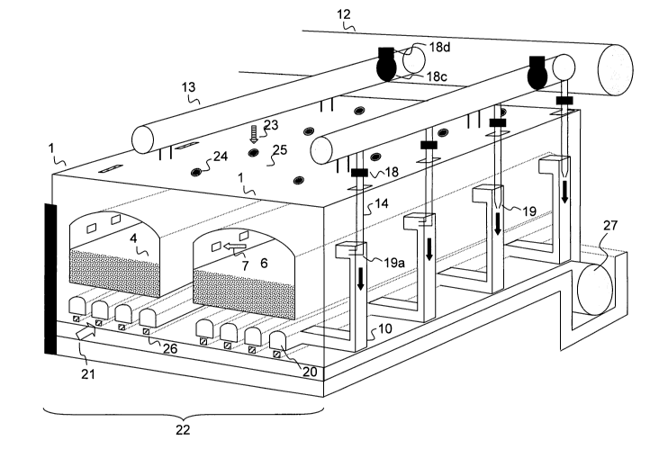
8 Openings of downcomer channels
9 Coke oven chamber wall
õDowncomer" channels
11 Carbonaceous deposits
12 Central compressed air mains
13 Ancillary piping
14 Piping as distribution main
Compressed air
16 Inspection opening ports
17 Top of coke oven chamber
18 Shutoff device
18a Slide gate
18b Electrical control device
18
CA 02810934 2013-03-08
18c Valve cock
18d Electrical control device
19 Pipe end of compressed air mains
19a Horizontally angled pipe end
20 Secondary heating spaces
21 Secondary air
22 Coke oven bank
23 Primary air
24 Primary air opening ports
25 Top of coke oven chamber
26 Secondary air soles
27 Central waste gas main
28 Coke oven chamber walls
29 Waste gas
30 Waste gas collecting duct
31 Digital computer unit
32 Measuring sensor
32a Pressure measuring sensor
32b Temperature measuring sensor
19