Note: Descriptions are shown in the official language in which they were submitted.
CA 02811039 2013-03-08
SWING ARM DEVICE FOR ELECTRIC TWO- OR THREE-WHEELED VEHICLE
FIELD OF THE INVENTION
The present invention relates to a swing arm device for an electric two- or
three-
wheeled vehicle, and particularly, relates to a swing arm vehicle for which a
battery
for an electric vehicle and a charger are disposed for an electric two- or
three-
wheeled vehicle including a swing arm.
BACKGROUND OF THE INVENTION
As a structure for fixing a battery in an electric vehicle such as an electric
motorcycle,
a fuel-cell motorcycle, or a hybrid motorcycle, there is disclosed a structure
in which
one end of a swing arm is coupled to a swing shaft, the other end of the swing
arm
supports the rear wheel, an electric motor for driving the rear wheel is
placed at the
other end side of the swing arm, and a battery is disposed at a position near
the
swing shaft of the swing arm, as disclosed in, for example, Japanese Published
Patent
Application No. 2008-221976.
Japanese Published Patent Application No. 2008-221976 describes disposing a
motor,
a PDU, and a battery in a swing arm, however, because the battery needs to be
charged, it is necessary to mount a charger on a vehicle body. In that case,
it is
WH-13932CA/lh
CA 02811039 2014-09-10
= -
WH-13932CA
SN 2,811,039
- 2 -
necessary to design where on the vehicle body side the charger is disposed,
and in
addition, it is also necessary to consider how wiring for the battery and
charger is
routed between the swing arm to swing and the vehicle body being a stationary
side.
SUMMARY OF THE INVENTION
One aspect of the present invention provides a swing arm device for an
electric two-
or three-wheeled vehicle suitable for an electric two- or three-wheeled
vehicle for
which a swing arm of an electric vehicle includes a motor, a control unit,
battery and
charger, the swing arm stores electrically-operated components integrally, and
wiring
is simplified as much as possible, and which does not require large
modification on
the vehicle body side.
In one aspect of the present invention provides a swing arm device for an
electric two-
or three-wheeled vehicle to be fitted on an electric vehicle including a swing
arm one
end of which is coupled to a swing shaft and the other end of which supports a
rear
wheel, an electric motor placed at the other end side of the swing arm and for
driving
the rear wheel, and a control unit and battery for supplying electric power to
the
electric motor, wherein a charger for charging the battery is incorporated in
the swing
arm.
According to the above aspect of the present invention, as a result of
incorporating the
charger in the swing arm, a reduction in wiring between the charger and the
battery
and concentration and compact placement of electrical components due to
integral
storage of the electrically-operated components can be achieved.
Moreover, the electrically-operated components that require large modification
on the
vehicle body side can be integrally stored.
CA 02811039 2014-09-10
WH-13932CA
SN 2,811,039
- 3 -
In another aspect of the invention, the control unit controls energization of
the electric
motor and is disposed at a front end side of the swing arm, the charger is
integrally
disposed on the control unit, while the charger includes a charge cord for
external
charging, a storage portion for storing the charge cord is provided on a
vehicle body
side of the electric vehicle, and the charge cord is routed into the storage
portion from
the control unit through near the swing shaft of the swing arm.
According to the above aspect of the present invention, electrical systems can
be
directly connected between the charger and the control unit, and the number of
components can be reduced by simplifying wiring cables.
In yet another aspect of the invention, components with small heat capacities
are
aggregated on a control board that is placed at a vehicle front side in the
control unit
and components with large heat capacities are disposed in a modularized manner
at a
rear end side of the swing arm with respect to the control board.
According to the above aspect of the present invention, disposing the
components of
the control unit in a modularized manner allows having optimal placement by
function, and space saving can be achieved.
In a further aspect of the invention, a storage portion for storing the charge
cord is
provided under a floorboard of the electric vehicle.
According to the above aspect of the present invention, when providing a
storage
portion of the charge cord, effective use of the dead floor space including
steps and a
step-over portion can be achieved.
CA 02811039 2013-03-08
- 4 -
In yet a further aspect of the invention, a storage portion for storing the
charge cord
is provided under a step of the electric vehicle.
According to the above aspect of the present invention, when providing a
storage
portion of the charge cord, effective use of the dead space under the step can
be
achieved.
In another aspect of the invention, a storage portion for storing the charge
cord is
provided below a storage box of the electric vehicle.
According to the above aspect of the present invention, when providing a
storage
portion of the charge cord, effective use of the dead space below the storage
box can
be achieved.
In yet another aspect of the invention, a lid for taking out the charge cord
is
provided in an exterior surface that covers the outside below the storage box.
According to the above aspect of the present invention, providing the
dedicated
take-out opening in the storing portion allows an improvement in convenience
when
taking out the charge cord.
In another aspect of the invention, a cap is included for insulation and
waterproofing
in a charging terminal at a tip of the charge cord.
According to the above aspect of the present invention, fitting the cap on the
charging terminal at the tip of the charge cord allows preventing electric
leakage and
deterioration of the terminal of the charge cord in a non-use state.
WI-13932CAph
CA 02811039 2013-03-08
- 5 -
In a further aspect of the invention, the charge cord has stretchability.
According to the above aspect of the present invention, the charge cord having
stretchability allows an improvement in ease of storing into the storage
portion.
In yet a further aspect of the invention, in a meter device for indicating a
vehicle state
placed on the electric vehicle, an indicator for confirming charge of the
charger is
provided.
According to the above aspect of the present invention, by providing the
indicator in
the meter device, and the indicator turning on to start charging and turning
off when
the charging is completed, charge confirmation can be easily performed.
BRIEF DESCRIPTION OF THE DRAWINGS
Preferred embodiments of the invention are shown in the drawings, wherein:
Fig. 1 is a left side view of an electric two-wheeled vehicle mounted with a
battery
for an electric vehicle of the present invention.
Fig. 2 is a left side view showing an example of an embodiment of a battery
for an
electric vehicle of the present invention, which shows a state where a cover
of a
swing arm part where the battery for an electric vehicle is disposed is
removed.
Fig. 3 is a top view of the swing arm part of Fig. 2 in which the battery for
an electric
vehicle is disposed.
Fig. 4 is an exploded perspective view of the swing arm.
WH-13932CA/lh
CA 02811039 2013-03-08
- 6 -
Fig. 5 is an enlarged sectional view of a reduction gear mechanism.
Fig. 6 is an explanatory sectional view showing a floor tunnel part in a
vehicle
having a floor tunnel.
Fig. 7 is a top view of the swing arm after potting process.
Fig. 8 is an explanatory plan view showing an example of a meter device
mounted
on a vehicle.
Fig. 9 is a block diagram showing a whole configuration of an electrical
system to be
applied to the electric two-wheeled vehicle.
Fig. 10 is a block diagram showing a configuration of a component circuitry of
only a
charger of an electrical system to be applied to the electric two-wheeled
vehicle.
DETAILED DESCRIPTION OF THE PREFERRED EMBODIMENTS
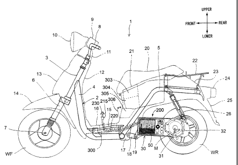
Hereinafter, preferred embodiments of the present invention will be described
in
detail with reference to the drawings. Fig. 1 is a side view of an electric
two-wheeled
vehicle 1 according to an embodiment of the present invention. The electric
two-
wheeled vehicle 1 is a scooter type saddle-type vehicle having a low
floorboard 16,
and drives a rear wheel WR by an electric motor M stored in a swing arm (unit
swing) 30. To a front portion of a vehicle body frame 2, a head pipe 3 that
pivotally
supports a stem shaft (not shown) so as to be freely rotatable is joined. To
an upper
WH-13932CAph
CA 02811039 2013-03-08
- 7 -
portion of the stem shaft, a steering handle 8 to be covered with a handle
cover 11 is
joined, and to a lower portion, on the other hand, a pair of left and right
front forks 6
that pivotally support a front wheel WF so as to be freely turnable by an axle
7 are
joined.
The vehicle body frame 2 includes a main pipe 4 extending downward from a rear
portion of the head pipe 3 and a rear frame 5 coupled to a rear end portion of
main
pipe 4 and extending upward in a vehicle-body rear portion. To the main pipe 4
located under the low floorboard 16, a floor frame 15 that supports the low
floorboard 16 is attached. Moreover, to a junction portion between the main
pipe 4
and the rear frame 5, a pair of left and right pivot plates 17 are attached.
The swing arm 30 is a cantilever type having an arm portion at only the left
side in
the vehicle width direction, and is pivotally supported on the vehicle frame 2
so as to
be freely swingable via a swing shaft 19 that penetrates through a link 18
attached to
the pivot plate 17. The swing arm 30 is a partially hollow structure made of a
metal
such as aluminum, in which the electric motor M is stored near an axle 32, and
a
board 50 serving as a control device is arranged in front of the electric
motor M in
the vehicle body. A battery 56 (refer to Fig. 3) that supplies electric power
to the
electric motor M is arranged on the right side in the vehicle width direction
of the
board 50.
The rear wheel WR is pivotally supported on the swing arm 30 so as to be
freely
rotatable by the axle 32, and a rear end portion of the swing arm 30 is
suspended
from the rear frame 5 via a rear cushion 26. Moreover, under a seat 20, a
storage box
21 to serve as a baggage locker space is disposed so as to be sandwiched by
the pair
of left and right rear frames 5.
WH-13932CA/lh
CA 02811039 2013-03-08
- 8 -
The main pipe 4 of the vehicle body frame 2 is covered with a front cowl 13 on
a side
forward of the vehicle body and a leg shield 12 on a side rearward of the
vehicle
body. On the top of the handle cover 11, a meter device 9 is arranged, and at
a side
forward of the vehicle body with respect to the meter device 9, a headlight 10
is
attached. To an upper portion of the front forks 6, a front fender 14 that
covers the
front wheel WF is fixed.
The outside of the rear frame 5 in the vehicle width direction is covered with
a seat
cowl 23, and a tail lamp device 24 is attached to a rear end portion of the
seat cowl
23. Above the tail lamp device 24, a rear carrier 22 joined to the rear frame
5 projects,
and below the tail lamp device 24, a rear fender 23 that covers the rear wheel
WR
from behind and above is provided.
Fig. 2 is an enlarged side view of the swing arm 30 mounted with a battery for
an
electric vehicle in a state where a cover is removed. Moreover, Fig. 3 is a
top view of
the swing arm 30, and Fig. 4 is an exploded perspective view of the swing arm
30.
The same reference signs as the above denote the same or equivalent parts. As
described above, the swing arm 30 is a partially hollow structure made of a
metal
such as aluminum, and provided as a cantilever type that supports the rear
wheel
WR by an arm portion 39 provided on the left side in the vehicle width
direction. In
a lower portion on a side forward of the vehicle body with respect to the
swing arm
30, a pair of left and right pivot flanges 36 each formed with a through-hole
19a for
the swing shaft 19 (refer to Fig. 1) are provided.
On a side upward of the vehicle body with respect to the pivot flanges 36, a
storage
space 35 into which the battery 56 consisting of a plurality of battery cells
is inserted
is formed, and a wide case portion 38 that forms an outer shell portion of the
storage
space 35 and the arm portion 39 are continuously formed via a curved portion
40. At
WH-13932CA/lh
CA 02811039 2013-03-08
- 9 -
the left side in the vehicle width direction of the storage space 35 and the
arm
portion 39, a thin plate-like swing arm cover 57 that covers the board 50 and
the
electric motor M in an integrated manner is attached.
To a rear end portion of the arm portion 39, reduction gear cases 33, 41 in
which
reduction gears that reduce the rotation speed of the electric motor M is
stored are
attached. The axle 32 projects toward the right side in the vehicle width
direction
from the reduction gear case 41, and to an end portion of the axle 32, a wheel
34 of
the rear wheel WR is fixed by a nut 32a. A tubeless tire is used for the rear
wheel
WR, and an air valve 42 is provided on the wheel 34. Moreover, on the
reduction
gear case 33, a mounting flange 37 formed with a through-hole 26a for
attaching the
rear cushion 26 (refer to Fig. 1) is provided.
Fig. 5 is an enlarged sectional view of a reduction gear mechanism 720. There
is
arranged a reduction gear mechanism between the electric motor M and the axle
32.
The swing arm 30 according to the present embodiment is a cantilever type that
supports the rear wheel WR by only a left arm portion, and at a position on a
side
rearward of the vehicle body of the arm portion, the electric motor M and the
reduction gear mechanism 720 are disposed in a concentrated manner.
The electric motor M is provided as an inner rotor type consisting of a stator
701
fixed to an inner wall of the swing arm 30 and having a stator coil and a
rotor 702
fixed to a motor drive shaft 705 via a collar 703. An end portion of the left
side in the
vehicle width direction of the motor drive shaft 705 is pivotally supported by
a
bearing 704 fitted in the swing arm cover 57. The right side in the vehicle
width
direction of the motor drive shaft 705 is pivotally supported by a bearing 707
fitted in
the reduction gear case 33 and a bearing 709 fitted in the reduction gear case
41. At
an end portion rearward of the vehicle body of the reduction gear case 33, a
support
VVH-13932CAph
CA 02811039 2013-03-08
- 10 -
hole 26a for a rear shock unit 26 is formed. In the swing arm cover 57, on a
side
forward of the vehicle body of the electric motor M, an output wiring 700 of
the
electric motor M is arranged.
Rotational drive force transmitted to the motor drive shaft 705 is transmitted
to the
final output shaft (axle) 32 via the reduction gear mechanism 720.
Specifically, the
rotational drive force is transmitted, via a first reduction gear wheel 713
that meshes
with a reduction gear 708 formed at an end portion of the right side in the
figure of
the motor drive shaft 705, a first reduction shaft 710 that is pivotally
supported so as
to be freely rotatable by a bearing 712 fixed to the first reduction gear
wheel 713 and
fitted in the reduction gear case 33 and a bearing 711 fitted in the reduction
gear case
41, and a second reduction gear wheel 715 that meshes with a reduction gear
formed
on the first reduction shaft 710, to the final output shaft 32 that is
pivotally
supported so as to be freely rotatable by a bearing 714 fixed to the second
reduction
gear wheel 715 and fitted in the reduction gear case 33 and a bearing 718
fitted in the
reduction gear case 41.
To an end portion of the right side in the figure of the final output shaft
32, the wheel
34 of the rear wheel WR is fixed via a collar 717. On the inner diameter side
of the
wheel 34, a brake drum having a liner 719 is formed, and inside thereof, a
pair of
upper and lower brake shoes (not shown) to be driven by a brake cam (not
shown) is
stored. On the side leftward in the figure with respect to the bearing 718, an
oil seal
716 is disposed.
Near the swing shaft on one end side of the swing arm 30, there is formed
inside a
square-shaped storage space 35 in an integrated manner. The storage space 35
is
arranged so that, when the swing arm 30 is fitted on an electric vehicle, an
opening
VVH-13932CAph
CA 02811039 2013-03-08
- 11 -
side (opening portion) of the storage space 35 is located lateral to the
electric vehicle,
and the battery 56 can be inserted from the opening side.
A battery for an electric vehicle, as a result of the battery 56 being
assembled onto
the board (control unit) 50 in an integrated manner, and being inserted and
fixed to
the storage space 35 of the swing arm 30 in the assembled state, is mounted on
an
electric two-wheeled vehicle by being directly fitted on the swing arm 30
without
using a dedicated case.
The battery 56 according to the present embodiment has a module structure
configured so as to obtain a predetermined high voltage by connecting a
plurality of
battery cells. The plate-like battery cells, which have been laminated with
their
planar portions oriented in the front-rear direction of the vehicle body, are
stored in
the storage space 35 having a substantially rectangular parallelepiped shape
formed
in the wide case portion 38. Accordingly, the battery 56 being a heavy object
is
disposed close to the swing shaft 19 of the swing arm 30, and the moment of
inertia
during swinging of the swing arm 30 is reduced to allow a smooth swing motion.
Moreover, the battery cells are provided as a laminate type where each cell is
packed
with a soft laminate sheet. By the laminate-type battery, not only can a high
energy
density and an improvement in heat dissipation performance be expected, but an
attaching operation to the swing arm 30 and a battery replacement operation
are also
facilitated.
The board (control unit) 50 serving as a control device internally containing
a battery
charger according to the present embodiment is arranged close to the battery
56 on
the left side in the vehicle width direction thereof. The board (control unit)
50
consists of a control board 50a, a heating element board 50b, and an aluminum
board
50c, and which are disposed so that their respective planar portions are
oriented in
WH-13932CA/lh
CA 02811039 2013-03-08
- 12 -
the vehicle width direction. The control board 50a is disposed close to the
battery 56
on the left side in the vehicle width direction thereof, and the heating
element board
50b is coupled to a side rearward of the vehicle body of the control board
50a. The
aluminum board 50c is disposed close to the battery 56 on the left side in the
vehicle
width direction thereof. Further, circuits and elements, etc., (a thermistor
51, a group
of input/output filters 52 for a charger, a charger power factor improving
inductor
53, a charger power factor improving capacitor 54, a DC output smoothing
capacitor
55) disposed in a dispersed manner on the respective boards compose a charger
200.
As a result of disposing the components on the respective boards in a
dispersed
manner to form a charger 200 and incorporating the charger 200 in the swing
arm 30,
electrical systems can be directly connected, and the number of components can
be
reduced by simplifying flexible wiring cables (harnesses).
A charge cord 220 for external charging connected to the charger 200 is stored
in a
storage portion 300 provided under the low floorboard 16. The charge cord 220
is
formed in a curled shape having stretchability, and to an AC plug (charging
terminal) 215 at its tip portion, a cap 230 for insulation and waterproofing
is freely
removably fitted. This arrangement allows for effective use of the dead space
under
the low floorboard 16. Moreover, forming the charge cord 220 in a curled shape
allows an improvement in ease of storing, and the freely removable cap 230
allows
preventing electric leakage and deterioration of the terminal of the charge
cord 220
in a non-use state.
Moreover, the storage portion 300 may include a winding device for the charge
cord
220.
In the foregoing example, the storage portion 300 is formed under the low
floorboard 16, however, as shown in, for example, Fig. 6, in the case of a
vehicle of a
WH-13932CAph
CA 02811039 2013-03-08
- 13 -
type having a floor tunnel 400, a storage portion 301 may be formed in a part
located
on the main pipe 4 that is inserted through the inside of the floor tunnel 400
in the
front-rear direction, and storage portions 302 may be formed under steps 401
located
on both sides of the floor tunnel 400. This arrangement allows for effective
use of the
dead floor space including the steps 401 and the floor tunnel (step-over
portion) 400.
Moreover, in the case of a vehicle including the storage box 21 that stores a
helmet
etc., under the seat 20, as shown in Fig. 1, a storage portion 303 or 304 may
be
provided at a position upward or position downward of the storage box 21.
Further,
when there is a space under the storage box 21, a storage portion 305 may be
provided in the space under the storage box 21. This arrangement allows for
effective use of the dead space below the storage box 21.
Further, providing a lid 306 for taking out the charge cord 220 in an exterior
surface
that covers the outside of the storage portion 305 can provide a structure
which
allows taking out the charge cord 220 without opening the seat 20. Providing a
dedicated take-out opening by the lid 306 allows an improvement in convenience
when taking out the charge cord 220.
Between the battery 56 and the aluminum board 50c, a sponge rubber 501 having
a
predetermined thickness width is disposed. In the sponge rubber 501, a
plurality of
slits for inserting a plate-like terminal 500 provided at the left end portion
in the
figure of each battery cell are formed. As a result of inserting the plate-
like terminal
500 into each slit, the position of the plate-like terminal is defined.
Moreover, by the
sponge rubber 501, the usage of a potting material 59 (refer to Fig. 5) during
a
potting process to be described later can be reduced for a reduction in weight
of the
swing arm 30. The aluminum board 50c is disposed close to the sponge rubber
501.
WH-13932CA/lh
CA 02811039 2013-03-08
- 14 -
On the control board 50a, elements for control signals that generate little
heat are
mounted. On the other hand, elements in which a large current flows to
generate
heat are mounted on the heating element board 50b and the aluminum board 50c.
Further, out of the heating elements, electronic components with large heat
capacities including the thermistor 51, the group of input/output filters 52
for a
charger, the charger power factor improving inductor 53, the charger power
factor
improving capacitor 54, and the DC output smoothing capacitor 55 are mounted
on
the heating element board 50b, and out of the heating elements, electronic
components with small heat capacities are mounted on the aluminum board 50c.
Thus, providing a heating element board 50b on which only heating elements
having
large calorific values are disposed in a concentrated manner allows a
reduction in a
heat load of heat generation of the heating elements mounted on the heating
element
board 50b to be applied to other elements. Moreover, separating the position
to
arrange heating elements from the position to arrange other control elements
allows
an increase in the degree of freedom of layout of the pivot flanges 39 and the
through-holes 19a, etc.
That is, in the board (control unit) 50, aggregating components that generate
little
heat on the control board 50a and disposing components with large heat
capacities in
a modularized manner on the heating element board 50b that is at a rear end
side of
the swing arm 30 with respect to the control board 50a allows having optimal
placement by function, and space saving can be achieved.
The battery cells that compose the battery 56 are arranged to be respectively
fixed to
the aluminum board 50c so that the control unit 50 is disposed at a front end
side of
the swing arm.
W1-1-13932CA/lh
CA 02811039 2013-03-08
- 15 -
As a result of the circuits of the control unit 50 being electrically
connected with the
respective battery cells, the battery 56 is charged, and a voltage from the
battery 56 is
supplied to the control board 50a to control driving of the electric motor M.
Moreover, by disposing the heating element board 50b on the side rearward of
the
vehicle body with respect to the control board 50a, effect of the thermal
influence of
the heating elements on the control board 50a located on the upstream side in
the
vehicle-body traveling direction can be prevented. Further, as a result of the
control
board 50a being disposed on the outside of the battery 56 in the vehicle width
direction, the thickness in the vehicle width direction can be reduced. Also,
because
the heating board 50b is arranged at a position to overlap with the rear wheel
WR in
a side view of the vehicle body, the heating elements can be arranged, taking
advantage of a space formed between the battery 56 and the electric motor M,
so that
an excessively long swing arm length can be prevented.
Moreover, as shown in Fig. 4, the battery 56, as a result of a predetermined
number
of cell plates being laminated in the front-rear direction of the vehicle
body, shows a
substantially rectangular parallelepiped shape where its longitudinal
direction is
oriented in the vehicle width direction, and is stored in the storage space 35
of the
wide case portion 38. On an inner surface 43 of the storage space 35, guide
grooves
44 to store the respective plate-like battery cells at predetermined
positions,
respectively, are formed.
The guide grooves 44 are arranged, by forming a plurality of groove portions
corresponding to the respective battery cells along the direction into which
the
battery 56 is inserted at an upper surface and lower surface in the storage
space 35,
so that, when storing the respective battery cells that compose the battery
56, side
surface portions of the cells (each cell) are fitted into the guide grooves 44
and can be
VVH-13932CAph
CA 02811039 2013-03-08
- 16 -
fixed in position. Providing the guide grooves 44 allows eliminating a
dedicated
component for holding the cells and having a compact configuration as a whole.
In the wide case portion 38, a through-hole 38a into which a sealing plug 45
is fitted
is formed. On the other hand, in a coupling plate 46 that couples the battery
56 and
the board (control unit) 50 in a position forward of the vehicle body, a
through-hole
47 into which the sealing plug 45 is fitted is formed. The sealing plug 45 and
the
through-holes 38a, 47 are used in a "resin potting process" that is performed
during
assembly of the swing arm 30. The potting process is for physically fixing the
battery
56 and the board (control unit) 50 to the swing arm 30 as well as obtaining
insulation
and vibration isolation of the board (control unit) 50, and further increasing
heat
dissipation of the respective portions.
The potting process is performed by inserting the battery 56 and the board
(control
unit) 50 into the wide case portion 38, performing positioning by fitting the
sealing
plug 47 into the through-holes 38a, 47, and then pouring the potting material
59
made of a liquid resin that hardens over time around the battery 56, with an
opening
portion of the wide case 38 facing upward. The potting material 59 is
injected, as
shown in Fig. 7, so as to cover the control board 50a and the aluminum board
50c
and cover a part on the side of a mounting surface of the capacitor 53, the
group of
various transformers 55, etc., mounted on the heating element board 50b. The
potting material 59 also has a function of increasing heat dissipation of the
battery 56
etc.
Then, by removing the sealing plug 45 after the potting material 59 hardens, a
communication hole that communicates the inside with the outside of the wide
case
portion 38 is formed at the position where the sealing plug 45 existed. By the
communication hole, even when a gas is discharged from the battery 56, the gas
is
WH-13932CAph
CA 02811039 2013-03-08
- 17 -
smoothly discharged to the outside, so that a rise in the pressure in the
swing arm 30
can be prevented.
That is, a high-pressure releasing escape passage that externally leads an air
pressure
(for high pressure release) when the ambient temperature of the battery having
reached a high temperature has risen can be formed by a potting material, so
that a
dedicated member for forming an escape passage can be eliminated.
The potting material poured into the storage space 35 from the periphery is
filled
around a space of the battery 56 stored in the storage space 35 to harden in a
state
where the potting material exists around a space including at least a coupling
part
with the control board 50a in an upper portion of the cells, so that the
position of the
battery 56 is fixed with respect to the storage space 35 due to interposition
of the
potting material. The swing arm cover 57 to serve as a lid body is covered in
this
state on the opening side of the storage space 35.
According to this structure, by fixing the battery 56 positioned in the
storage space
35 by interposition of the potting material, the battery 56 can be mounted in
the
swing arm 30 in an integrated manner. Moreover, by fixing the control board
50a
together with the battery (battery cells) 56 by potting, a dedicated fixing
component
can be eliminated.
In the meter device 9, as shown in Fig. 8, an indicator 250 for confirming
charge of
the charger 200 is provided. This indicator 250 is arranged so as to turn on
when the
AC plug (charging terminal) 215 of the charge cord 220 is taken out of the
storage
portion and inserted in an external outlet to start charging and turn off when
the
charging is completed. Accordingly, because the AC plug (charging terminal)
215
WH-13932CA/lh
CA 02811039 2013-03-08
- 18 -
can be pulled out of the outlet after the indicator 250 turns off, charge
confirmation
can be easily performed.
According to the foregoing arrangement, by making a dedicated case for holding
the
battery 56 no longer necessary and using the swing arm 30 itself as a case to
hold the
battery 56, a reduction in the number of components and a reduction in weight
can
be performed despite reliably fixing the battery 56 to the swing arm 30.
Because a structure in which the battery 56 being a heavy object can be
incorporated
later is provided, vehicle assemblability is improved, and it is also not
necessary to
make the swing arm 30 partially bulge in line with the shape of the battery
56, which
thus contributes to a reduction in the number of components and a reduction in
weight, while the battery 56 can be reliably fixed to the swing arm 30.
Directly fixing the battery 56 to the swing arm 30 allows using the swing arm
30 as a
heat sink, so that the effect of cooling the battery 56 can be improved.
Moreover, as a result of simplifying the mounting structure of the battery 56,
the
battery unit as a whole can be made compact, and the degree of freedom in
design
with respect to other configurations, such as placement of electrical
components, can
be improved.
Fig. 9 and Fig. 10 are block diagrams showing a configuration of an electrical
system
to be applied to the electric two-wheeled vehicle 1. The same reference signs
as the
above denote the same or equivalent parts. Fig. 10 shows a component circuit
of
only a charger, and Fig. 9 shows an overall configuration other than the same.
In
Figs. 9 and 10, elements mounted on the control board 50a are shown by "broken
lines," elements mounted on the aluminum board 50c are shown by "alternate
long
WH-13932CA/lh
CA 02811039 2013-03-08
- 19 -
and short dashed lines," and elements mounted on the heating element board 50b
are shown by thick "solid lines."
On the control board 50a, elements for control signals in which a small
current flows
are mounted. These elements generate little heat, and the control board 50a is
formed by a glass epoxy board. Moreover, on the aluminum board 50c, elements
in
which a large current flows and which are incapable of self-heat dissipation
are
mainly mounted. Examples of these electronic components include a
semiconductor
element (FET, diode), a resistor, and a film capacitor, and these are
increased in heat
dissipation by being mounted on the highly heat-conductive aluminum board 50c.
Further, on the heating element board 50b, large-sized electronic components
in
which a large current flows and which are capable of self-heat dissipation are
mainly
mounted. Examples of these electronic components include an inductor, a
transformer, and an electrolytic capacitor, and the heating element board 50b
is
arranged at a position where the influence of battery heat is unlikely to be
received
to obtain an improvement in heat dissipation.
Also, in the block diagrams of Figs. 9 and 10, elements mounted on the heating
element board 50b are an input filter 209 and an output filter 201
(corresponding to
the above-described group of input/output filters 52), a PFC circuit 207
(corresponding to the above-described charger power factor improving capacitor
53), and an AC-DC transformer 204 (corresponding to the above-described
charger
DC-converting capacitor 54) of the charger 200 and a DC-DC transformer 108
(corresponding to the above-described group of various transformers 55) and an
output filter 110 of a DC-DC section 106.
Referring to Fig. 9, the lithium ion battery 56 is electrically connected to
an input side
of an inverter 123 via a contactor 104, and an output side of the inverter 123
is
WH-13932CA/lh
CA 02811039 2013-03-08
- 20 -
connected to the electric motor M by a three-phase alternating current line.
To the
contactor 104 that is on/off controlled by a mechanical contact that operates
with an
electromagnetic force, a pre-charge relay 105 that prevents a surge in supply
current
is connected in parallel.
A BMU (Battery Management Unit) 100 includes a monitoring circuit (ASIC) 101
for
the voltage, temperature, etc., of the battery 56, a cell balance discharging
unit 102
for correcting a variation in the capacity of battery cells, and a controller
103 that
controls these.
Between the controller 103 in the BMU 100 and a controller 122 serving as a
control
device for controlling the inverter 123, respective lines for a permanent
system 116, a
control system 117, a main switch system 118, and CAN communication 119 are
arranged. Moreover, an overcharge alert signal 120 is transmitted from the
controller 103 of the BMU 100, and a contactor control signal 121 is
transmitted from
the controller 122 of the inverter 123.
To the controller 122 of the inverter 123, sensor signals are input from an
angle
sensor 124 that detects the rotation angle of the electric motor M, a throttle
sensor
125 that detects the throttle operation amount by a rider, a seat SW (switch)
126 that
detects whether the rider is seated on the seat 20, a side stand SW 127 that
detects
whether a side stand (not shown) of the electric vehicle 1 is retracted, and a
bank
angle sensor 129 that detects the inclination (bank angle) of the electric
vehicle. A
buzzer 128 serving as an alarm is actuated in response to an actuation signal
from
the controller 122 when an overdischarged state or the like of the battery 56
is
detected.
WH-13932CAph
CA 02811039 2013-03-08
- 21 -
The permanent line 116 is connected to the DC-DC section 106 that converts a
large
current supplied from the battery 56 to a control current. The DC-DC section
106
includes a primary-side drive unit 107, a DC-DC transformer 108, an output
rectifier
circuit 109, an output filter 110, a primary-side driver IC 113 that supplies
a PWM
signal to the primary-side drive unit 107, and a secondary-side driver IC 114
that
supplies a PWM signal to the output rectifier circuit 109. To the primary-side
driver
IC 113, a start signal 115 is supplied from the controller 122. Moreover, to
the
permanent line 116, one-end sides of an antitheft alarm unit 133 and a main SW
136
are connected.
The control line 117 is connected to the controller 122 of the inverter 123.
To the
control line 117, one end of a meter indicator 132 serving as an actuation
indicator
lamp of the antitheft alarm unit 133 is connected. Moreover, the meter
indicator 132
is connected with a speed sensor that detects a vehicle speed, and the meter
indicator
132 is arranged so as to function as a speed warning lamp when the vehicle
speed
exceeds a predetermined value.
To the main SW line 118, lamps 130 such as blinkers, a headlight (H/L) 10, and
general electrical equipment 131 such as a battery cooling fan. An end portion
of the
main SW line 118 is connected to an automatic power-off relay 135 that enables
actuation of the headlight 10 etc., under a predetermined condition even if
the main
SW 136 is turned off.
Referring to Fig. 10, to the charger 200, input and output lines (A, B) of a
direct
current to be connected to the battery 56 and an AC plug 215 to be connected
to a
commercial alternating current power supply, or the like are connected. The
charger
200 includes an input filter 209, a bridge diode 208, a PFC circuit 207
serving as a
power factor improving circuit, a primary-side drive unit 206, an AC-DC
WH-13932CAph
CA 02811039 2013-03-08
- 22 -
transformer 204, an output rectifier circuit 203, and an output filter 201. A
signal of
an overcurrent detection circuit 212 disposed between the primary-side drive
unit
206 and the AC-DC transformer 204 is input to a PFC-PWM driver IC 213. On the
other hand, a signal of a voltage detection circuit 202 connected to the
output filter
201 is input to a PFC-PWM driver IC 213 via a photocoupler 205. The PFC
circuit 207
and the primary-side drive unit 206 are driven by PWM signal 210 output from
the
PFC-PWM driver IC 213, respectively. To the PFC-PWM driver IC 213, a start
signal
214(c) from the controller 122 of the inverter 123 is input.
The scope of the claims should not be limited by the preferred embodiments set
forth
in the examples, but should be given the broadest interpretation consistent
with the
description as a whole.
WH-13932CA/lh