Note: Descriptions are shown in the official language in which they were submitted.
CA 02811042 2013-03-08
WO 2012/044660 PCT/US2011/053617
RAZOR HANDLE WITH A ROTATABLE PORTION
FIELD OF THE INVENTION
The invention generally relates to handles for razors, more particularly to
handles with a
rotatable portion.
BACKGROUND OF THE INVENTION
Recent advances in shaving razors, such as a 5-bladed or 6-bladed razor for
wet shaving,
may provide for closer, finer, and more comfortable shaving. One factor that
may affect the
closeness of the shave is the amount of contact for blades on a shaving
surface. The larger the
surface area that the blades contact then the closer the shave becomes.
Current approaches to
shaving largely comprise of razors with only a single axis of rotation, for
example, about an axis
substantially parallel to the blades and substantially perpendicular to the
handle (i.e., front-and-
back pivoting motion). The curvature of various shaving areas, however, does
not simply
conform to a single axis of rotation and, thus, a portion of the blades often
disengage from the
skin during shaving as they have limited ability to pivot about the single
axis. Therefore, blades
on such razors may only have limited surface contact with certain shaving
areas, such as under
the chin, around the jaw line, around the mouth, etc.
Razors with multiple axes of rotation may help in addressing closeness of
shaving and in
more closely following skin contours of a user. For example, a second axis of
rotation for a razor
can be an axis substantially perpendicular to the blades and substantially
perpendicular to the
handle, such as side-to-side pivoting motion. Examples of various approaches
to shaving razors
with multiple axes of rotation are described in U.S. Patent Nos. 5,029,391;
5,093,991; 5,526,568;
5,560,106; 5,787,593; 5,953,824; 6,115,924; 6,381,857; 6,615,498; and
6,880,253; U.S. Patent
Application Publication Nos. 2009/066218; 2009/0313837; 2010/0043242; and
2010/0083505;
and Japanese Patent Laid Open Publication Nos. H2-34193; H2-52694; and H4-
22388.
However, to provide another axis of rotation, such as an axis substantially
perpendicular to the
blades and substantially perpendicular to the handle; typically, additional
parts are implemented
with increased complexity and movement. Furthermore, these additional
components often
require tight tolerances with little room for error. As a result, current
approaches introduce
complexities, costs, and durability issues for manufacturing, assembling, and
using razors with
multiple axes of rotation.
CA 02811042 2013-03-08
WO 2012/044660 PCT/US2011/053617
2
What is needed, then, is a razor, suitable for wet or dry shaving, with
multiple axes of
rotation, for example, an axis substantially perpendicular to the blades and
substantially
perpendicular to the handle and an axis substantially parallel to the blades
and substantially
perpendicular to the handle. The razor, including powered and manual razors,
is preferably
simpler, cost-effective, reliable, durable, easier and/or faster to
manufacture, and easier and/or
faster to assemble with more precision.
SUMMARY OF THE INVENTION
In one aspect, the invention relates to a handle for a shaving razor. The
handle comprises
a frame and a pod operably coupled to the frame such that the pod is
configured to rotate about
an axis substantially perpendicular to the frame. The pod comprises a base and
a cantilever tail
extending from the base. A distal end of the cantilever tail is not fixed in
position and/or is
loosely retained by the frame. The cantilever tail generates a return torque
upon rotation of the
pod about the axis.
The foregoing aspect can include one or more of the following embodiments. The
frame
can define at least one aperture therethrough and the base can comprise at
least one projection
extending therefrom. The at least one aperture of the frame can be configured
to receive the at
least one projection of the base to couple the pod to the frame such that the
at least one projection
can rotate in the at least one aperture so that the pod can rotate about the
axis. Each of the at
least one aperture and the at least one projection can be generally
cylindrical. The frame can
comprise a substantially rigid cradle such that the pod can be coupled to the
cradle. The frame
can also comprise at least one wall loosely retaining the distal end of the
cantilever tail. The
distal end of the cantilever tail can move or flex upon rotation of the pod.
The at least one wall
can comprise a first wall and a second wall that are offset such that the
first wall and the second
wall can be substantially parallel and non-coplanar. The cradle, the first
wall, and the second
wall can be integrally formed. The pod can be unitary. Substantially all of
the cantilever tail can
flex when the pod rotates. The cantilever tail can form a substantially T-
shaped configuration
comprising an elongate stem and a perpendicular bar at the distal end of the
cantilever tail such
that the perpendicular bar is loosely retained by the frame. Each of the
elongate stem and the
perpendicular bar can be generally rectangular. A thickness of the elongate
stem can flare larger
towards the base. The perpendicular bar can be twisted when the pod is in an
at rest position.
The perpendicular bar can be twisted about 5 degrees to about 10 degrees when
the pod is in the
at rest position. The elongate stem may not contact the frame. The elongate
stem can generate
CA 02811042 2013-03-08
WO 2012/044660 PCT/US2011/053617
3
the return torque upon rotation of the pod. The pod can be configured to
rotated about +/- 24
degrees from an at rest position. The return torque of the cantilever tail can
be in a range of
about 8 N*mm to about 16 N*mm when the pod has been rotated about 12 degrees
from an at
rest position.
In another aspect, the invention relates to a shaving razor. The shaving razor
comprises a
handle comprising a frame and a blade cartridge connecting assembly operably
coupled to the
frame such that the blade cartridge connecting assembly is configured to
rotate about a first axis
substantially perpendicular to the frame. The blade cartridge connecting
assembly comprises a
pod in the pod comprises a base and a cantilever tail extending from the base.
A distal end of the
cantilever tail is loosely retained by the frame. The cantilever tail
generates a return torque upon
rotation of the pod. The shaving razor also comprises a blade cartridge unit
releasably attached
to the blade cartridge connecting assembly. The blade cartridge unit comprises
at least one blade
and the blade cartridge unit is configured to rotate about a second axis
substantially parallel to the
at least one blade. The blade cartridge unit is configured to rotate about the
first axis and the
second axis when connected to the blade cartridge connecting assembly.
This aspect can include one or more of the following embodiments. The frame
can define
at least one aperture therethrough and the base can comprise at least one
projection extending
therefrom. The at least one aperture of the frame can be configured to receive
the at least one
projection of the base to couple the pod to the frame such that the at least
one projection can
rotate in the at least one aperture so that the pod can rotate about the axis.
The frame can
comprise a substantially rigid cradle such that the pod can be coupled to the
cradle. The frame
can further comprise at least one wall loosely retaining the distal end of the
cantilever tail. The
cradle and the at least one wall can be integrally formed. A portion of the
cantilever tail may not
contact the frame. The return torque of the cantilever tail can be in a range
of about 8 N*mm to
about 16 N*mm when the pod has been rotated about 12 degrees from an at rest
position. The
blade cartridge connecting assembly can further comprise a docking station
releasably attached to
the base of the pod such that the blade cartridge unit can be releasably
attached to the docking
station.
BRIEF DESCRIPTION OF THE DRAWINGS
Other features and advantages of the present invention, as well as the
invention itself, can
be more fully understood from the following description of the various
embodiments, when read
together with the accompanying drawings, in which:
CA 02811042 2013-03-08
WO 2012/044660 PCT/US2011/053617
4
FIG. 1 is a schematic perspective view of a rear of a shaving razor in
accordance with an
embodiment of the invention;
FIG. 2 is a schematic perspective view of a front of the shaving razor of FIG.
1;
FIG. 3 is a schematic perspective view of a rear of a handle of a shaving
razor according
to an embodiment of the invention;
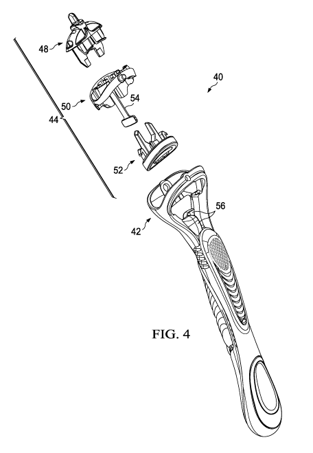
FIG. 4 is a schematic exploded perspective view of the handle of FIG. 3;
FIG. 5 is a schematic perspective view of a pod in accordance with an
embodiment of the
invention;
FIG. 6 is a schematic rear view of the pod of FIG. 5;
FIG. 7 is a schematic perspective view of a front of the pod of FIG. 5;
FIG. 8 is a schematic side view of the pod of FIG. 5;
FIG. 9 is a schematic perspective view of a portion of a frame of a handle
according to an
embodiment of the invention;
FIGS. 10A-10E depict a procedure for assembling a portion of a handle
according to an
embodiment of the invention;
FIG. 11 depicts a procedure for compressing a pod in accordance with an
embodiment of
the invention;
FIGS. 12A-12C depict a schematic front view of a pod and a portion of a frame
of a
handle during various stages of rotation according to an embodiment of the
invention; and
FIG. 13 is a schematic perspective view of a portion of a cantilever tail of a
pod and a
portion of a frame of a handle in accordance with an embodiment of the
invention.
DETAILED DESCRIPTION OF THE INVENTION
Except as otherwise noted, the articles "a," "an," and "the" mean "one or
more."
Referring to FIGS. 1 and 2, a shaving razor 10 of the present invention
comprises a
handle 20 and a blade cartridge unit 30, which removably connects or
releasably attaches to the
handle 20 and contains one or more blades 32. The handle 20 comprises a frame
22 and a blade
cartridge connecting assembly 24 operably coupled thereto such that the blade
cartridge
connecting assembly 24 is configured to rotate about an axis of rotation 26
that is substantially
perpendicular to the blades 32 and substantially perpendicular to the frame
22. The blade
cartridge unit 30 is configured to rotate about an axis of rotation 34 that is
substantially parallel
to the blades 32 and substantially perpendicular to the handle 20. Nonlimiting
examples of
suitable blade cartridge units are described in U.S. Patent No. 7,168,173.
When the blade
CA 02811042 2013-03-08
WO 2012/044660 PCT/US2011/053617
cartridge unit 30 is attached to the handle 20 via the blade cartridge
connecting assembly 24, the
blade cartridge unit 30 is configured to rotate about multiple axes of
rotation, for example, a first
axis of rotation 26 and a second axis of rotation 34.
FIGS. 3 and 4 depict an embodiment of a handle 40 of the present invention.
The handle
5 40 comprises a frame 42 and a blade cartridge connecting assembly 44
operably coupled thereto
such that the blade cartridge connecting assembly 44 is configured to rotate
about an axis of
rotation 46 that is substantially perpendicular to the frame 42. The blade
cartridge connecting
assembly 44 comprises a docking station 48 engageable with a blade cartridge
unit (not shown), a
pod 50, and an ejector button assembly 52. The pod 50 is operably coupled to
the frame 42, such
that it is rotatable relative to the frame 42, with the docking station 48 and
the ejector button
assembly 52 removably or releasably attached to the pod 50. Nonlimiting
examples of suitable
docking stations and ejector button assemblies are described in U.S. Patent
Nos. 7,168,173 and
7,690,122 and U.S. Patent Application Publication Nos. 2005/0198839,
2006/0162167, and
2007/0193042. In an embodiment, the pod 50 is flexible such that it is
separable from the frame
42. The pod 50 comprises a cantilever tail 54 in which a distal end of the
cantilever tail 54 is
loosely retained by a pair of offset walls 56 of the frame 42. The cantilever
tail 54 generates a
return torque when the pod 50 is rotated about axis 46 such that the pod 50 is
returned to an at
rest position. Nonlimiting examples of suitable springs retained between walls
to generate a
return torque are described in U.S. Patent No. 3,935,639 and 3,950,845 and
shown by the
Sensor 3 disposable razors (available from the Gillette Co., Boston,
Massachusetts).
FIGS. 5 through 8 depict a pod 60 of the present invention. The pod 60
comprises a base
62 with one or more projections 64 and a cantilever tail 65 extending
therefrom. The projections
64 may extend from any exterior portion of the base 62. In an embodiment, the
projections 64
are generally cylindrical. By "generally cylindrical" the projections 64 may
include non-
cylindrical elements, e.g., ridges, protrusions, or recesses, and/or may
include regions along its
length that are not cylindrical, such as tapered and/or flared ends due to
manufacturing and
design considerations. Additionally or alternatively, one or more of the
projections 64 may
include a bearing pad 66 of larger size between the projections 64 and the
base 62. For example,
each of the projections 64 may include a bearing pad 66 of larger size between
the projections 64
and the base 62. In an embodiment, the cantilever tail 65 forms a
substantially T-shaped
configuration comprising an elongate stem 67 and a perpendicular bar 68 at a
distal end. In an
embodiment, the elongate stem 67 and the perpendicular bar 68 are each
generally rectangular.
By "generally rectangular" the elongate stem 67 and the perpendicular bar 68
may each include
CA 02811042 2013-03-08
WO 2012/044660 PCT/US2011/053617
6
non-rectangular elements, e.g., ridges, protrusions, or recesses, and/or may
include regions along
its length that are not rectangular, such as tapered and/or flared ends due to
manufacturing and
design considerations. For example, a thickness (T) of the elongate stem 67
may gradually flare
larger towards a proximal end of the elongate stem 67 relative to the base 62.
Gradually flaring
the thickness of the elongate stem 67 may help to reduce stress concentrations
when the pod 60 is
rotated so that yield stresses of the material of the elongate stem 67 will
not be exceeded, which
if exceeded would result in failure such as permanent deformation or fatigue
with repeated use.
Similarly, a height (H) of the elongate stem 67 may flare larger, e.g.,
gradually flare larger or
quickly flare larger, towards a distal end of the elongate stem 67, as the
elongate stem 67
approaches the perpendicular bar 68. In this arrangement, a length (L1) of the
elongate stem 67
can be maximized to achieve desirable stiffnesses and return torques when the
pod 60 is rotated.
Alternatively, the elongate stem 67 and the perpendicular bar 68 may each form
any geometric,
polygonal, or arcuate shape, e.g., an ovoid shape. An interior of the pod 60
defines a hollow
portion therethrough with two open ends, for example, a top end and a bottom
end. Interior
surfaces of the pod 60 may optionally include projections extending into the
hollow portion,
grooves, channels, and/or detents to engage corresponding mating shapes of a
docking station at
one end of the pod 60 and an ejector button assembly at another end of the pod
60. The
cantilever tail 65 extends from a front portion 69 of the base 62, though the
cantilever tail 66 may
alternatively extend from a rear portion 70 of the base 62.
In the present invention, a single component, specifically the pod 60, serves
multiple
functions. The pod 60 facilitates an axis of rotation in a razor handle,
namely an axis of rotation
substantially perpendicular to one or more blades when a razor is assembled
and substantially
perpendicular to a frame of a handle. When rotated from an at rest position,
the pod 60 generates
a return torque to return to the rest position by way of a spring member, such
as a cantilever
spring or a leaf spring. The return torque is generated by the cantilever tail
65 of the pod 60. For
example, the return torque is generated by elongate stem 67 of the cantilever
tail 65. The pod 60
also serves as a carrier for an ejector button assembly, a docking station,
and/or a blade cartridge
unit (e.g., via the docking station).
In an embodiment, the pod 60 is unitary and, optionally, formed from a single
material.
Additionally or alternatively, the material is flexible such that the entire
pod 60 is flexible.
Preferably, the pod 60 is integrally molded such that the cantilever tail 65,
which comprises the
elongate stem 67 and the perpendicular bar 68, and the base 62 are integrally
formed. A unitary
design ensures that the base 62 and the cantilever tail 65 are in proper
alignment to each other.
CA 02811042 2013-03-08
WO 2012/044660 PCT/US2011/053617
7
For example, the position of the cantilever tail 65 relative to an axis of
rotation is then controlled,
as well as the perpendicular orientation of the base 62 and the cantilever
tail 65. Furthermore,
the base 62 and the cantilever tail 65 do not separate upon drop impact.
Referring now to FIG. 9, a portion of a frame 72 of a handle comprises a
cradle 74 and
one or more apertures 76 defined in the cradle 74. In an embodiment, the
apertures 76 are
generally cylindrical. By "generally cylindrical" the apertures 76 may include
non-cylindrical
elements, e.g., ridges, protrusions, or recesses, and/or may include regions
along its length that
are not cylindrical, such as tapered and/or flared ends due to manufacturing
and design
considerations. Furthermore, the cradle 74 can be open at least at one end and
define a hollow
interior portion. Additionally or alternatively, a bearing surface 77 may
surround one or more of
the apertures 76 such that the bearing surface 77 extends into the hollow
interior portion. For
example, bearing surfaces 77 may surround each of the apertures 76. One or
more walls 78 may
have a portion thereof that extends into the hollow interior portion. In an
embodiment, a pair of
walls 78 may each have a portion that extends into the hollow interior
portion. Optionally, the
pair of walls 78 may be offset such that they are not in opposing alignment.
For example, the
walls 78 can be generally parallel and generally non-coplanar. Furthermore,
the pair of walls 78
may be arranged so that they do not overlap. Top surfaces 79 of the walls 78
may have a lead-in
surface, such as a sloped top surface or a rounded edge top surface to lead a
distal end of a
cantilever tail of a pod into and between the walls 78 during assembly.
Additionally or
alternatively, the hollow interior portion may also include at least one shelf
80 or at least one
sloped surface that at least partially extends into the hollow interior
portion.
In one embodiment, the cradle 74 forms a closed, integral loop to provide
structural
strength and integrity. Alternatively, the cradle 74 does not form a closed
loop, but is still
integrally formed. Where the cradle 74 does not form a closed loop, the cradle
74 can be made
thicker for added strength and integrity. In forming an integral structure,
the cradle 74 does not
require separate components for assembly; separate components may come apart
upon drop
impact. An integral structure facilitates easier manufacturing, e.g., via use
of a single material,
and when the cradle 74 is, optionally, substantially rigid or immobile, the
rigidity helps to
prevent the apertures 76 from spreading apart upon drop impact and thus helps
to prevent release
of an engaged pod. Thus, the cradle 74 can be durable and made from non-
deforming material,
e.g., metal diecast, such as zinc diecast, or substantially rigid or immobile
plastic. The rigidity of
the cradle 74 also facilitates more reliable control of the distance of the
apertures 76 as well as
their concentric alignment. In an embodiment, the cradle 74 is integrally
formed with the walls
CA 02811042 2013-03-08
WO 2012/044660 PCT/US2011/053617
8
78 to form one component. Additionally or alternatively, the entire frame 72
of the handle can
be substantially rigid or immobile in which soft or elastic components may be
optionally
disposed on the frame 72 to assist with a user gripping the razor.
FIGS. 10A through 10E depict a procedure for assembling a handle of the
present
invention. A frame 82 of the handle comprises a cradle 84 defining an opening
at least at one
end and a hollow interior portion therein. Each of a pair of offset walls 86
of the frame 82 has a
portion thereof that extends into the hollow interior portion. A flexible pod
90 comprises a base
92 and a flexible cantilever tail extending from the base 92. The cantilever
tail comprises an
elongate stem 94 and a perpendicular bar 96 at a distal end thereof. To engage
the frame 82 and
the pod 90, the pod 90 is positioned (Step 1) within the hollow interior
portion of the frame 82
and aligned such that a first mounting member 98 of the pod 90 correspond in
shape and align
with a second mounting member 100 of the frame 82 and the perpendicular bar 96
of the
cantilever tail is located near the walls 86 of the frame 82. In an
embodiment, the first mounting
member 98 of the pod 90 comprise one or more projections extending from the
base 92 and the
second mounting member 100 of the frame 82 comprise one or more apertures
formed in the
cradle 84. To assist in preventing improper alignment and engagement of the
pod 90 and the
cradle 84, in embodiments with a plurality of projections extending from the
base 92 and a
plurality of apertures formed in the cradle 84, one of the projections is
larger than the other
projections and one of the corresponding apertures is larger than the other
apertures.
Additionally or alternatively, the first mounting member 98 of the pod 90
comprise one or more
apertures formed in the base 92 and the second mounting member 100 of the
frame 82 comprises
one or more projections extending into the hollow interior portion of the
cradle 84. The base 92
and/or the first mounting member 98 of the pod 90 are then compressed and
positioned (Step 2)
such that the first mounting member 98 aligns with the second mounting member
100 and the
perpendicular bar 96 is located between the walls 86. When decompressed, the
first mounting
member 98 mates with the second mounting member 100 and the perpendicular bar
96 is loosely
retained by the walls 86. In an embodiment, of the cantilever tail, only the
distal end of the
cantilever tail, specifically the perpendicular bar 96, contacts the frame 82
when the pod 90 is
decompressed. For example, substantially all of the elongate stem 94 of the
cantilever tail does
not contact the frame 82. In an embodiment in which the pod 90 comprises
bearing pads and the
cradle 84 comprises bearing surfaces, when the pod 90 is coupled to the cradle
84, the bearing
pads of the pod 90 are configured such that substantially the remaining
portions of the base 92
(e.g., other than the bearing pads and the first mounting member 98) do not
contact the cradle 84.
CA 02811042 2013-03-08
WO 2012/044660 PCT/US2011/053617
9
Having only the bearing pads and the first mounting member 98 contact the
cradle 84 serves to
reduce or minimize the friction and/or resistance of the pod 90 when rotated
relative to the cradle
84. A portion of a docking station 102 is then positioned (Step 3) within a
hollow interior
portion of the pod 90 and then mated (Step 4) to the pod 90 such that
extensions of the docking
station 102 correspond in shape and mate with grooves and/or detents on an
interior surface of
the pod 90. In an embodiment, the docking station 102 is substantially rigid
such that the pod 90
is locked into engagement with the frame 82 when the docking station 102 is
coupled to the pod
90. Additionally or alternatively, the docking station 102 is stationary
relative to the pod 90. For
example, wires can stake the docking station 102 to the pod 90. In an
embodiment, when the
docking station 102 is staked to the pod 90, the docking station 102 can
expand the pod 90, for
example, the distance between the projections, beyond the pod's 90 as-molded
dimensions. An
ejector button assembly 104 corresponds in shape and mates (Step 5) with the
pod 90 by aligning
and engaging extensions of the ejector button assembly 104 with corresponding
grooves and/or
detents on the interior surface of the pod 90. In an embodiment, once the
ejector button assembly
104 is engaged to the pod 90, the ejector button assembly 104 is movable
relative to the pod 90
and the docking station 102 such that movement of the ejector button assembly
104 ejects an
blade cartridge unit attached to the docking station. In an alternative
embodiment, the ejector
button assembly 104 can be engaged to the pod 90 before the docking station
102 is engaged to
the pod 90.
FIG. 11 depicts a procedure for compressing and decompressing a flexible pod
110,
which comprises a base 112 and one or more projections 114 extending from the
base 112. In an
embodiment, the entire pod 110 is flexible and, therefore, compressible such
that the pod 110 is
engageable with a frame 116 (shown in sectional view in FIG. 11) defining one
or more apertures
118 and a hollow interior portion. To engage the pod 110 to the frame 116,
similar as to
discussed above, the pod 110 is positioned (Step 1) within the hollow interior
portion of the
frame 116. The base 112 and/or the projections 114 of the pod 110 are then
compressed (Step
2A) such that the projections 114 freely clear the hollow interior portion of
the frame 116 and the
projections 114 can then align with the apertures 118. By compressing the base
112 along the
portions with the projections 114, the base 112 and the projections 114 of the
pod 110 fit
substantially entirely within the hollow interior of the frame 116. When
decompressed (Step
2B), the pod 110 is free to spring back to is open, natural position and the
projections 114 mate
with the apertures 118. In an embodiment, when decompressed, the projections
114 penetrate
deep into the apertures 118 for a secure fit into the frame 116, which can be
substantially rigid or
CA 02811042 2013-03-08
WO 2012/044660 PCT/US2011/053617
immobile. Additionally or alternatively, the projections 114 correspond in
size and mate with the
apertures 118 via a pin arrangement, ball and socket arrangement, snap-fit
connection, and
friction-fit connection.
A distal end of the projections 114 can be disposed about or near an exterior
surface of
5 the frame 116. In such an arrangement, robustness of the entire razor
assembly need not be
compromised so that features can jump each other in assembly. Additionally,
separate features
or components are unnecessary to achieve deep penetration into the apertures
118. For example,
the apertures 118 are not defined by more than one component and the apertures
118 do not need
to be partially open on the top or bottom to engage the projections 114 into
the apertures 118.
10 Because the frame 116 is formed from substantially rigid or immobile
material, the projections
114 and the apertures 118 can be designed to engage without requiring any
secondary activity,
such as dimensional tuning, to ensure proper positioning while also minimizing
the slop of the
pod 110 when rotating relative to the frame 116. In an embodiment, the frame
116 is integrally
formed with the walls, such as a pair of offset walls, to form one
substantially rigid or immobile
component. In such an arrangement, the rest position of the pod 110 is more
precisely
controlled.
FIGS. 12A though 12C depict a portion of a handle during various stages of
rotation. A
flexible pod 120 comprises a base 122 with projections 124 and a cantilever
tail 126 extending
therefrom. The cantilever tail 126 comprises an elongate stem 127 and a
perpendicular bar 128
at a distal end thereof. A frame 134 defines one or more apertures 136, and
the frame 134 also
comprises a pair of offset walls 138. FIG. 12A depicts a rest position of the
pod 120 with respect
to the frame 134 when no forces are being applied to the pod 120. In an
embodiment, the
cantilever tail 126 can have a spring preload when engaged with the frame 134
which minimizes
or eliminates wobbliness of the pod 120 when the pod 120 is in the rest
position. The spring
preload provides stability to a blade cartridge unit upon contact with a
shaving surface. In such
an arrangement, the rest position of the pod 120 is a preloaded neutral
position. Aligning the pod
120 in the preloaded neutral position relative to the frame 134 and
establishing the spring preload
are precisely controlled due to the pod 120 being a single, unitary component
and the frame 134
and the walls 138 being formed from a single, unitary component. Further, by
loosely retaining
the perpendicular bar 128 of the cantilever tail 126 with a pair of offset
walls 138, the
requirement for clearance, for example, to account for manufacturing errors
and tolerances,
between the perpendicular bar 128 and the walls 138 is minimized or
eliminated. The offset of
the walls 138 allows the perpendicular bar 128 to spatially overlap the walls
138 without having
CA 02811042 2013-03-08
WO 2012/044660 PCT/US2011/053617
11
the walls 138 grip or restrain the perpendicular bar 128, thereby avoiding the
necessity of
opposing retaining walls. Opposing retaining walls require clearance between
the walls and the
perpendicular bar to allow for free movement of the perpendicular bar and for
manufacturing
clearances. Such a clearance would result in unrestrained or sloppy movement
of the pod 120 at
the preloaded neutral position as well as perhaps a zero preload.
Alternatively, opposing
retaining walls without clearance would pinch the perpendicular bar and
restrict motion.
When forces are applied to the pod 120, for example, via the blade cartridge
unit when
coupled to the pod 120, the pod 120 can rotate relative to the frame 134. The
projections 124 of
the pod 120 are sized such that the projections 124 rotate within the
apertures 136 to facilitate
rotation of the pod 120. In such an arrangement, when the pod 120 is engaged
to the frame 134,
the projections 124 can only rotate about an axis, but not translate. In an
embodiment, the
projections 124 have a fixed axis (i.e., the concentric alignment of the
apertures 136) that it can
rotate about. Additionally or alternatively, the projections 124 can be sized
so that frictional
interference within the apertures 136 provides certain desirable movement or
properties. When
the pod 120 is rotated, because the perpendicular bar 128 of the pod 120 is
loosely retained by
the pair of offset walls 138, the offset walls 138 interfere with and twist
the perpendicular bar
128 of the pod 120 such that the elongate stem 127 flexes. Optionally,
substantially all of the
cantilever tail 126, including the elongate stem 127 and the perpendicular bar
128 flexes or
moves during rotation. Alternatively, upon rotation, only a portion of the
cantilever tail 126,
specifically the elongate stem 127, flexes or moves. In flexing, the
cantilever tail 126 generates a
return torque to return the pod 120 to the rest position. In an embodiment,
the elongate stem 127
generates the return torque upon rotation of the pod 120. The larger the
rotation of the pod 120,
the larger the return torque is generated. The range of rotation from the
preloaded neutral
position can be about +/- 4 degrees to about +/-24 degrees, preferably about
+/- 8 degrees to
about +/-16 degrees, and even more preferably about +/- 12 degrees. The frame
134 of the
handle can be configured to limit the range of rotation of the pod 120. In an
embodiment,
shelves or sloping surfaces that extend into the interior of the frame 134 can
limit the range of
rotation of the pod 120 in that an end of the pod 120 will contact the
respective shelf or sloping
surface. The return torque can be either linear or non-linear acting to return
the pod 120 to the
rest position. In an embodiment, when rotated to +/- 12 degrees from the rest
position, the return
torque can be about 12 N*mm.
Various return torques can be achieved through combinations of material choice
for a pod
and dimensions of a cantilever tail. In various embodiments, to achieve a
desired return torque,
CA 02811042 2013-03-08
WO 2012/044660 PCT/US2011/053617
12
the material and/or shape of the pod can be selected from a range of a highly
flexible material
with a thick and/or short cantilever tail to a substantially rigid material
with a thin and/or long
cantilever tail. A range of desired return torque can be about 0 N*mm to about
24 N*mm,
preferably about 8 N*mm to about 16 N*mm, and even more preferably about 12
N*mm.
Preferably, the pod is formed from thermoplastic polymers. For example,
nonlimiting examples
of materials for the pod with desirable properties, such as flexibility,
durability (breakdown from
drop impact), fatigue resistance (breakdown from bending over repeated use),
and creep
resistance (relaxing of the material), can include PolylacC) 757 (available
from Chi Mei
Corporation, Tainan, Taiwan), Hytre1C) 5526 and 8283 (available from E. I.
duPont de Nemours
& Co., Wilmington, Delaware), ZytelC) 122L (available from E. I. duPont de
Nemours & Co.,
Wilmington, Delaware), CelconC) M90 (available from Ticona LLC, Florence,
Kentucky),
Pebax(i) 7233 (available from Arkema Inc., Philadelphia, Pennsylvania),
CrastinC) S500,
S600F20, S600F40, and S600LF (available from E. I. duPont de Nemours & Co.,
Wilmington,
Delaware), CelenexC) 1400A (M90 (available from Ticona LLC, Florence,
Kentucky), DelrinC)
100ST and 500T (available from E. I. duPont de Nemours & Co., Wilmington,
Delaware),
HostaformC) XT 20 (available from Ticona LLC, Florence, Kentucky), and
SurlynC) 8150
(available from E. I. duPont de Nemours & Co., Wilmington, Delaware).
Furthermore, the
selection of a material may affect the stiffness and yield stress of the pod
or an elongate stem of
the cantilever tail. For example, each material may have different stiffnesses
depending on the
temperature and rate of rotation of the pod relative to the frame. Dimensions
of the cantilever tail
can be varied to achieve a desired torque and/or a desired stiffness. For
example, the cantilever
tail can be thicker and/or shorter (for increased stiffness), as well as
thinner and/or longer (for
decreased stiffness). In an embodiment, the thickness of the cantilever tail,
about its widest
point, can be about 0.1 mm to about 3.5 mm, preferably about 0.4 to about 1.8
mm, even more
preferably about 1.5 mm. The length of the cantilever tail can be about 3 mm
to about 25 mm,
preferably about 11 mm to about 19 mm, and even more preferably about 16 mm,
such as about
16.6 mm. The height of the cantilever tail can be about 0.5 mm to about 14 mm,
preferably
about 2 mm to about 8 mm, and even more preferably about 6 mm, such as about
6.2 mm.
For example, referring back to FIGS. 5 through 9, a pod 60 of the present
invention can
be molded from one material, such as DelrinC) 500T. To achieve a return torque
of the cantilever
tail 65 of 12 N*mm when the pod 60 has been rotated +/- 12 degrees from an at
rest position
(e.g., a preloaded neutral position), a length Li of the elongate stem 67 is
about 13.4 mm. A
thickness T of the elongate stem 67, measured around its thickest point at
about a mid-point
CA 02811042 2013-03-08
WO 2012/044660 PCT/US2011/053617
13
along the length Li of the elongate stem 67, is about 0.62 mm. A height H of
the elongate stem
67 is about 2.8 mm. The perpendicular bar 68 of the cantilever tail 65 has a
thickness t,
measured around its widest point, of about 1.2 mm. In this embodiment, the
thickness t of the
perpendicular bar 68 is generally thicker than the thickness T of the elongate
stem 67, The
thickness t of the perpendicular bar 68 affects the preload of the cantilever
tail 65, but the
thickness t of the perpendicular bar 68 may not generally affect the bending
of the elongate stem
67 and, thus, may not affect the return torque when the pod 60 is rotated from
the rest position.
In an embodiment, a height h of the perpendicular bar 68 is greater than the
height H of the
elongate stem 67. For example, the height H of the perpendicular bar 68 can be
in the range of
about 0.2 times to about 5 times the height h of the elongate stem 67,
preferably about 2.2 times
the height H of the elongate stem 67 (e.g., about 6.2 mm). A length L2 of the
perpendicular bar
68 is about 3.2 mm.
When the pod 60 is coupled to the frame 72 of a handle and the perpendicular
bar 68 is
loosely retained by the pair of offset walls 78, a distance between the center
of the height h of the
perpendicular bar 68 to the point of contact with an offset wall 78 can be in
a range of about 0.4
mm to about 5mm, preferably about 2.1 mm such that generally a distance
between the offset
walls 78 is about 4.2 mm. In an embodiment, the dimensions between the walls
78 can vary with
the dimensions of the cantilever tail 65. When the pod 60 is coupled to the
frame 72 of the
handle, the twist of the perpendicular bar 68 is about 9.4 degrees such that
one of the offset walls
78 laterally displaces the point of contact of the perpendicular bar 68 in a
range of about 0.1 mm
to about 1.0 mm, preferably about 0.33 mm. The aperture 76 on the front of the
frame 72 is
preferably about 3.35 mm in diameter and an aperture 76 on the rear of the
frame 72 is preferably
about 2.41 mm in diameter. In an embodiment, any of the apertures 76 of the
frame 72 can have
a diameter sized in the range of about 0.5 mm to about 10 mm. The
corresponding projections 64
of the base 62 of the pod 60 are preferably about 3.32 mm and about 2.38 mm in
diameter,
respectively. In an embodiment, any of the projections 64 of the base 62 can
have a diameter
sized in the range of about 0.5 mm to about 11 mm. Due to molding of the pod
60, proximal
portions of the projections 64 of the pod 60 can be tapered. Additionally or
alternatively, the
corresponding apertures 76 of the frame 72 can be tapered or not tapered. A
distance between
bearing surfaces 77 within an interior of the frame 72 is preferably about
12.45 mm. In an
embodiment, a distance between bearing surfaces 77 can be in the range of
about 5 mm to about
20 mm. When the pod 60 is coupled to the frame 72 and a docking station (not
shown) is
CA 02811042 2013-03-08
WO 2012/044660 PCT/US2011/053617
14
coupled to the pod 60, a distance between the bearing pads 66 of the pod 60
can be in the range
of about 5 mm to about 20 mm, preferably about 12.3 mm.
In an embodiment, to achieve similar stiffness and/or return torques of the
elongate stem
67 using other materials, the thickness of the elongate stem 67 can be varied.
For example,
forming the pod 60 from HostaformC) XT 20, the thickness Ti of the elongate
stem 67 can be
increased about 13% to about 23 %, preferably about 15% to about 21%, and even
more
preferably about 18%. Forming the pod 60 from DelrinC) 100ST, the thickness Ti
of the
elongate stem 67 can be increased about 14% to about 24%, preferably about 16%
to about 22%,
and even more preferably about 19%.
FIG. 13 depicts a portion of a cantilever tail 140 when a pod is in a rest
position (e.g., a
preloaded neutral position). In an embodiment, a thickness of a perpendicular
bar 142 and/or the
spacing of a pair of offset walls 144 can be configured such that the
perpendicular bar 142 or the
entire cantilever tail 140 is twisted, thus forming a spring preload for the
cantilever tail 140,
when the pod is in the rest position. For example, the angle of twist of the
perpendicular bar 142
when the pod is in the preloaded neutral position can be in the range of about
2 degrees to about
degrees, preferably about 8 degrees to about 10 degrees, and even more
preferably about 9.4
degrees. Additionally or alternatively, the offset walls 144 loosely retain
the perpendicular bar
142 without gripping or restraining motion of the perpendicular bar 142 when
the perpendicular
bar 142 is twisted in the rest position.
20 The frame, pod, ejector button assembly, docking station, and/or blade
cartridge unit are
configured for simplification of assembly, for example, in high-speed
manufacturing. Each
component is configured to automatically align and to securely seat. In an
embodiment, each
component engages to another component in only a single orientation such that
the components
cannot be inaccurately or imprecisely assembled. Further, each component does
not need an
25 additional step of dimensional tuning or any secondary adjustment in
manufacturing to ensure
proper engagement with other components. The design of the handle also
provides control and
precision. For example, when the razor is assembled, the pod and/or the blade
cartridge unit is
substantially centered, the preload of the cantilever tail and/or the
perpendicular bar of the pod is
controlled precisely over time even after repeated use, and the performance of
the cantilever tail,
for example, acting as a spring, is controlled, consistent, and robust.
It should be understood that every maximum numerical limitation given
throughout this
specification includes every lower numerical limitation, as if such lower
numerical limitations
were expressly written herein. Every minimum numerical limitation given
throughout this
CA 02811042 2014-10-24
specification includes every higher numerical limitation, as if such higher
numerical limitations
were expressly written herein. Every numerical range given throughout this
specification
includes every narrower numerical range that falls within such broader
numerical range, as if
such narrower numerical ranges were all expressly written herein.
5 The dimensions and values disclosed herein are not to be understood as
being strictly
limited to the exact numerical values recited. Instead, unless otherwise
specified, each such
dimension is intended to mean both the recited value and a functionally
equivalent range
surrounding that value. For example, a dimension disclosed as "40 mm" is
intended to mean
"about 40 mm."
The citation of any document is not an admission that it is prior art with
respect to any invention disclosed or claimed herein or that it alone, or in
any combination with
any other reference or references, teaches, suggests or discloses any such
invention. Further, to
the extent that any meaning or definition of a term in this document conflicts
with any meaning
or definition of the same term in a document cited herein, the meaning or
definition
assigned to that term in this document shall govern.
While particular embodiments of the present invention have been illustrated
and
described, the scope of the claims should not be limited by the embodiments
set forth in
the drawings, but should be given the broadest interpretation consistent with
the
description as a whole.