Note: Descriptions are shown in the official language in which they were submitted.
CA 02811124 2013-03-04
WO 2012/031321
PCT/A112011/001149
1
A WORKER PROTECTION METHOD
TECHNICAL FIELD
The present invention generally relates to a worker protection method. The
present invention has particular. although not exclusive application to
protecting railroad workers.
BACKGROUND
The reference to any prior art in this specification is not, and should not be
taken as an acknowledgement or any form of suggestion that the prior art
forms part of the common general knowledge.
Teams of railroad workers invariably repair and maintain railroad tracks. Each
team generally includes a team coordinator who coordinates the activities of
the team members.
In practice, the team is often required to work proximal to a railroad track
during times when trains are running. The team leader in radio communication
with a command centre can verbally request that the command centre divert
trains to other tracks to ensure team safety, However, the applicant is aware
of instances where the command centre did not correctly act upon such a
request, and a train has still been diverted along a track upon which the team
is working which is extremely dangerous.
The Applicant perceives a need for an improved protection method for
protecting the team.
SUMMARY OF THE INVENTION
According to one aspect of the present invention, there Is provided a worker
protection method for protecting at least one worker using a portable
computational device, the method including the steps of:
CA 02811124 2013-03-04
WO 2012/031321 PCT/AU2011/001149
2
sending a protection request for allocation of a protection zone for at
least one worker; and
receiving confirmation that the protection zone has been allocated.
The protection zone may be circular. The protection zone may be static or
dynamic. The received confirmation may include verbal confirmation via voice
communication.
The method may further include the step of monitoring the location of the
worker relative to the protection zone. The step of monitoring may involve
continually receiving the location of the worker. The method may further
involve the step of sending a warning alarm to each worker or a command
centre based upon the location of the worker relative to the protection zone.
The warning alarm may have a severity indicator.
The method may further include the step of determining that a hazard Is co-
incident or intersecting with the protection zone. The method may further
include the step of sending a warning notification to the worker regarding the
hazard. The hazard may be related to a vehicle or plant, The hazard may be a
train or protection zone of the train, and the method may further include the
step of sending a warning notification to the train. The method may further
include the step of automatically reducing the speed of the train upon receipt
of the warning notification.
The method may further involve the step of sending a relinquishment request
for relinquishing (or handing back) the protection zone upon completion of
work by the worker.
The method may further include the step of receiving health information
relating to the worker.
According to another aspect of the present invention, there is provided a
portable computational device for protecting at least one worker, the device
configured to:
CA 02811124 2013-03-04
WO 2012/031321 PCT/A U2011
/001149
3
send a protection request for allocation of a protection zone for at least
one worker; and
receive confirmation that the protection zone has been allocated,
The device may include a global positioning system unit. The device may
include a transceiver for communicating with handheld devices borne by the
workers, a command centre and a vehicle or plant. The portable device may
be configured to periodically verify that it is in communication with each
handheld device, The device may include a biometric sensor arrangement for
authorizing operation of the device. Alternatively, the device may include an
identification reader (e.g. RFID or barcode reader) for identifying an
identifier
borne by an operator prior to authorizing operation of the device,. The device
may have a touch screen display user Interface. The touch screen display
may be configured to display a map showing the protection zone and the
location of the workers relative to the protection zone. The map may further
show the location of a train relative to the protection zone.
According to another aspect of the present invention, there is provided a
worker protection method for protecting at least one worker using a computer
system, the method including the steps of:
receiving a protection request for allocation of a protection zone for at
least one worker;
allocating said protection zone; and
sending confirmation that the protection zone has been allocated.
The method may further include the step of relinquishing the protection zone.
According to another aspect of the present invention, there is provided a
computer system for protecting at least one worker, the computer system
being configured to:
receive a protection request for allocation of a protection zone for said
at least one worker;
allocate said protection zone; and
send confirmation that the protection zone has been allocated.
CA 02811124 2013-03-04
WO 2012/031321 PCT/AU20111001149
4
BRIEF DESCRIPTION OF THE DRAWINGS
Preferred features, embodiments and variations of the invention may be
discerned from the following Detailed Description which provides sufficient
information for those skilled in the art to perform the invention, The
Detailed
Description is not to be regarded as limiting the Scope of the preceding
Summary of the Invention in any way. The Detailed Description will make
reference to a number of drawings as follows:
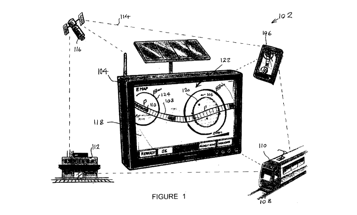
Figure 1 is a schematic view of a railroad worker protection system in
accordance with an embodiment of the present invention;
Figure 2 is a block diagram Of a portable computational device of the worker
protection system of Figure 1;
Figure 3 is a flowchart of a railway worker protection method in accordance
with an embodiment of the present invention, the method performed using the
protection system of Figure 1.
DETAILED DESCRIPTION OF PREFERRED EMBODIMENTS
In accordance with an embodiment of the present invention, there is provided
a railroad worker protection system 102 as shown in Figure 1. The system
102 can be used to protect a team of railway workers using a portable
computational device 104 carried by a leader of the team. The system 102
further includes handheld devices 5 carried by respective other workers of the
team. The team works proximal to a railway track 106 along which a train 110
can pass.
Each of the portable computational device 104, handheld devices 108 and
train 110 are in two-way communication with a computer system of a
command centre 112 via a communications network 114 (generally
designated by dashed lines). Furthermore, each of these system entities can
CA 02811124 2013-03-04
WO 2012/031321 PCT/AU2011/001149
communicate with each other via the network 114. The network 114 can
include communication via satellite 116, dedicated radio and mobile phone
infrastructure_
The portable device 104 can monitor the real-time location of the handheld
devices 106 carried by the team. The portable device 104 has a touch screen
display user interface 118_ The portable device 104 is configured to send, to
the command centre 112, a protection request for allocation of a circular
protection zone 120 for the team. The team can safely work within this
protection zone 120, The portable device 104 is further configured to receive
confirmation from the command centre 112 that the protection zone 120 has
been allocated. Subsequent to allocation, the touch screen display 118 is
configured to display a map 122 showing the protection zone 120 and the
location of the handheld devices 106 carried by the workers relative to the
protection zone 120.
The map 122 further shows the location of the tracks 108, train 110 and a
train protection zone 124 relative to the team protection zone 1,20. in the
reek
time event of the train protection zone 124 and the team protection zone 120
coinciding (or intersecting), the portable device 104 sends an alarm to each
handheld device 106, the command centre 112 and the train 110. If handheld
devices 106 carried by the workers leave the protection zone 120, the
portable device 104 sends a warning alarm to each handheld device 106 and
the computer system of the command centre I 12.
Turning to Figure 2, the portable device 104 includes a controller 200 for
controlling the operation of the device 104, The controller 200 contains a
software product 202 in resident memory. In turn, the software product 202
contains computer readable instructions for execution by a processor 204 of
the controller 200 to perform the railway worker protection method outlined
below. The processor 204 is interfaced to a storage device (e.g. hard disc)
containing a map feature database 206.
The portable device 104 further includes a Qlobal Positioning System (GPS)
208 for determining the location of the portable device 104. The portable
CA 02811124 2013-03-04
WO 2012/031321 PCT/AU2011/001149
6
device may also receive asset information for determining the location of the
portable device 104 and team leader. This asset information may relate to
asset numbers, monument numbers or identification numbers and tags that
are present on Infrastructure assets around a track worksite.
The portable device 104 further includes a transceiver 210 for enabling
communication with the other system entities via the network 114. The
portable device 104 also includes a biometric sensor arrangement 212 for
authorizing operation of the device 104 by the team leader, Alternatively. ,
the
device 104 includes an identification reader 214 (e.g. RFID or barcode reader)
for identifying an identifier (e.g. RFID tag or barcode) borne by the team
leader prior to authorizing operation of the device 104 by the teem leader.
The portable device 104 also includes a warning light 216 and warning siren
218 for providing visual and audible warnings to the team leader.
Each handheld device 106 and the computer system of the command centre
112 is of like construction to the portable device 104 of Figure 2.
A railroad worker protection method 300 performed using the protection
system 102 is now described.
Initially, the team of railway workers make their way to a worksite adjacent
the
railway track 108. The team leader carries the portable device 104 and the
other workers carry the handheld device 106.
At step 302, the portable device 104 sends a protection request message for
allocation of the protection zone 120 for the team. In turn, the computer
system of the command centre 112 receives the protection request meSsage.
At step 304, the computer system of the command centre 112 allocates the
protection zone 120. The protection zone 120 is typically static and circular
with the instantaneous location of the portable device 104 at its centre.
Accordingly, the protection zone 120 is located proximal the railroad track
108
CA 02811124 2013-03-04
WO 2012/031321
ITT/AU2011/1101149
7
or can be located near some other known static object (e.g. level crossing,
location marker, signal lights, access gate, etc.).
At step 306, the computer system of the command centre 112 sends
confirmation as an electronic message that the protection zone 120 has been
allocated. in turn, the portable device 104 receives the confirmation. The
received confirmation may also include a verbal confirmation via voice
communication.
At step 308, the portable device 104 monitors the location of the handheld
devices 106 carried by the workers relative to the protection zone 102. In
this
manner, the portable device 104 periodically receives the GPS location of
each handheld device 106.
At query step 310, the portable device 104 queries whether any of handheld
devices 106 carried by the workers have left the protection zone 120. If so,
at
step 312 the portable device 104 sends an appropriate warning alarm to each
handheld device 106 and the computer system of the command centre 112,
as well as activates the warning light 216 and warning siren 218. If not, the
method 300 proceeds to step 314.
At query step 314, the portable device 104 queries whether a hazard is co-
incident (or intersects) with the protection zone 120. The hazard i the train
110 or the train protection zone 124 of the train 110. if a hazard is co-
Incident
with the protection zone 120, the method 300 proceeds to step 312 where the
portable device 104 sends an appropriate warning alarm to each handheld
device 106, the computer system of the command centre 112 and the train
110. The portable device 104 also activates the warning light 216 and warning
siren 218, The speed of the approaching train 110 can be automatically
reduced (to zero) upon receipt of the warning alarm.
if a hazard is not co-incident with the protection zone 120, the method 300
proceeds to step 316,
CA 02811124 2013-03-04
WO 2012/031321
PCT/ATJ2011/001149
8
At step 316, the portable device 104 queries whether input is received from
the teem leader indicating that the protection zone can be relinquished upon
completion of work by the team. If so, the portable device 104 sends a
relinquishment request to the computer system of the command centre 112. in
turn at step 318, the command centre computer system receives the
relinquishment request and relinquishes the protection zone 120.
If at step 316, no input is received from the team leader indicating that the
protection zone can be relinquished, the method 300 returns to step 308.
The portable device 104 is configured to periodically verify with a heartbeat
signal that it is in communication with each handheld device 108 when the
protection zone 120 is allocated. In the event that the portable device 104
loses communication with one of the handheld devices 106, the portable
device 104 generates an audible and visual alarm with the warning siren 218
and the warning light 218.
Each handheld device 106 is configured to monitor health information (e.g.
heartbeat) of its associated worker and to send the health information to the
portable device 104. The portable device 104 is configured to receivie the
health information and can generate a health alarm responsive to determining
that the health information is indicative of unacceptable health, The portable
device 104 is configured to send the health alarm to each handheld device
106 and the command centre computer system.
A person skilled in the art will appreciate that many embodiments and
variations can be made without departing from the ambit of the present
invention.
The portable device 104 of the preferred embodiment was configured to send
a warning alarm of high severity to each worker's handheld device or the
command centre 112 upon detecting that one of the workers has left the
protection zone 120. In another embodiment, the portable device 104 is
CA 02811124 2013-03-04
WO 7012/031321 PCT/AU2011/001149
9
configured Send a warning alarm of lesser severity upon detecting that one of
the workers is about to leave (or is in close proximity to the edge of) the
protection zone 120 and is in a cautionary severity area.
At step 314 above, the portable device 104 queries whether a hazard in the
form of a train 110 or train protection zone 124 is co-incident (or
intersects)
with the worker protection zone 120. In another embodiment, the hazard may
instead include a railroad maintenance truck or associated truck protection
zone .
In the preferred embodiment, the worker protection zone 120 was static
around the work site. In an alternative embodiment, the worker protection
zone 120 may be dynamic (i.e. able to vary in location) and have the. portable
deviee 104 at its centre.
In one embodiment, the protection system 102 may include a automatic track
warning system (ATI/VS) which detects the real-time location of the train 110.
The ATVVS can include RF, RADAR, and/or switch activation detectors.
In compliance with the statute, the invention has been described in language
more or less specific to structural or methodical features. It is to be
understood that the invention is not limited to specific features shown or
described since the means herein described comprises preferred forms of
putting the invention into effect. The invention it, therefore, claimed in any
of
its forms or modifications within the proper scope of the appended claims
appropriately interpreted by those skilled in the art,