Note: Descriptions are shown in the official language in which they were submitted.
CA 02811308 2013-03-13
WO 2012/042475 PCT/1B2011/054253
1
MULTI-BALLOON DILATION DEVICE FOR PLACING CATHETER
TUBES
FIELD OF THE INVENTION
The present invention relates to catheters such as feeding tubes and their
placement in the body of a patient.
BACKGROUND
Numerous situations exist in which a body cavity needs to be catheterized
to achieve a desired medical goal. One relatively common situation is to
provide
nutritional solutions or medicines directly into the stomach or intestines. A
stoma is
formed in the stomach or intestinal wall and a catheter is placed through the
stoma. This surgical opening and/or the procedure to create the opening is
commonly referred to as "gastrostomy". Feeding solutions can be injected
through
the catheter to provide nutrients directly to the stomach or intestines (known
as
enteral feeding). A variety of different catheters intended for enteral
feeding have
been developed over the years, including some having a "low profile" relative
to
the portion of the catheter which sits on a patient's skin, as well as those
having
the more traditional or non-low profile configuration. These percutaneous
transconduit catheters (sometimes referred to as "percutaneous transconduit
tubes") are frequently referred to as "gastrostomy catheters", "percutaneous
gastrostomy catheters", "PEG catheters" or "enteral feeding catheters". U.S.
Patent
No. 6,019,746 for a "Low Profile Balloon Feeding Device" issued to Picha et
al. on
February 1, 2000, provides an example of one device.
These catheters are frequently placed in a procedure called percutaneous
endoscopic gastrostomy (frequently referred to as PEG). Traditionally, a PEG
tube
is placed using endoscopic guidance or x-ray guidance. In a conventional PEG
procedure that places a PEG tube into a patient's stomach, an endoscope is
used
to observe that the patient's esophagus is unobstructed and to inspect and
inflate
the stomach to see that the area selected for the gastrostomy can be
distended.
If the location is suitable, this spot is selected. In some types of
procedures,
prior to placement of any feeding tube, it has been found that it is
particularly
CA 02811308 2013-03-13
WO 2012/042475 PCT/1B2011/054253
2
desirable to anchor the anterior wall of the gastric lumen (e.g., the stomach)
to the
abdominal wall as a step prior to creating the stoma tract through the two.
Thus
attachment has been found to be critical as it helps to prevent inadvertent
separation and exposure of the peritoneal cavity to contamination and possible
peritonitis. This procedure is also applicable to jejunostomy or gastro-
jejunostomy
as well as the gastrostomy procedure referred to above. Similar procedures may
also be applicable or desirably for other catheter tubes such as peritoneal
drainage
tubes.
After the wall of the lumen is anchored, a needle is inserted into the patient
in the area in the appropriate location. Additionally, a small incision may be
made
in the skin. An endoscopist will then typically watch through the endoscope as
a
needle pushes through the patient's skin, then through the abdominal wall, and
enters the gastric lumen in the selected area to form a needle tract. A guide
wire is
passed through the needle into the gastric lumen (e.g., the stomach). The
endoscopist will use an endoscopic snare to grasp the guide wire firmly. The
snare, passed through the working channel of the endoscope, firmly grabs the
guide wire. Both the endoscope and snare are then withdrawn together through
the patient's mouth, pulling the guide wire with them. The end of the guide
wire that
extends out from the patient's mouth is subsequently attached to a PEG tube
and
the other end of the guide wire remains outside the patient's skin in the
abdominal
region.
The PEG tube is guided into the patient's mouth (while the endoscope is
completely removed from the patient) and pulled into the patient's gastric
lumen as
the guide wire is pulled from the end that remains outside the patient's skin.
Once
the PEG tube is in the gastric lumen, it is pulled partially through the
gastric and
abdominal walls until a bumper of the PEG tube is snug against the gastric
mucosa. However, in order for the PEG tube to be pulled partially through the
gastric and abdominal walls and skin, the original needle tract must be
dilated.
This dilation is carried out with conventional dilation devices that employ a
tapered
dilator at the distal end of the PEG tube so that it dilates the opening as it
is pulled
through the gastric mucosa. During such dilation, the endoscope is again
passed
CA 02811308 2013-03-13
WO 2012/042475 PCT/1B2011/054253
3
into the patient and subsequently used to visually observe that the bumper of
the
PEG tube is snug against the gastric mucosa.
In other conventional PEG tube placement procedures, endoscopy is not
used at all. Instead, x-ray techniques are used to help select a particularly
suitable
location in the patient's body (e.g., the stomach) for the introduction of the
PEG
lo tube. X-ray is used for guiding the PEG tube placement and for
inspecting the PEG
tube's final position.
There are many problems associated with these conventional procedures
including: increased risk of esophageal trauma associated with multiple passes
of
an endoscope into and out of a patient; placement of the PEG in an improper
location, transit of a large catheter tube such as a PEG through the
esophagus;
and/or additional complications and/or trauma of anchoring the wall of the
lumen to
the abdomen. While avoiding these problems may be desirable, suitable devices
or procedures are lacking.
Accordingly, there is a need for a device, system and method for placing a
non-vascular catheter tube such as a PEG tube in a patient that reduces these
risks and trauma and is easy to perform.
SUMMARY
In response to the difficulties and problems discussed herein, the present
invention provides a dilation device and dilation system. The dilation device
is an
inflatable device that is used for placing catheter tubes in a non-vascular
lumen,
desirably under direct visualization using an endoscope. Since the stomach is
a
common example of a non-vascular lumen, for the purpose of describing the
present invention, the use of the term "gastric lumen" or "stomach" is
representative of all other non-vascular lumens or spaces (e.g., duodenum,
jejunum, ileum, peritoneal cavity, etc.), unless otherwise specified.
According to the invention, a conventional endoscope is advanced into the
stomach to insufflate and allow palpation to locate an appropriate site. Once
the
appropriate site is located, a needle is inserted into the stomach through the
abdomen from outside the body to form a needle tract. A guide wire is then
introduced into the stomach through the needle, and a system is provided for:
CA 02811308 2013-03-13
WO 2012/042475 PCT/1B2011/054253
4
positioning a dilation device in the needle tract; maintaining the dilation
device in
the desired position; dilation of the needle tract, and removal of the
dilation device.
The dilation device includes at least an inflatable dilation balloon and an
inflatable retention balloon, an inflation lumen to inflate and deflate the
dilation
balloon, an inflation lumen to inflate and deflate the retention balloon, a
tubular
support, and a continuous pathway through the device that accommodates a guide
wire. The dilation balloon may be compliant, semi-compliant, or non-compliant:
The device may have a distal end and a proximal end. At least one dilation
balloon is located towards the distal end of the device. The dilation
balloon(s) has
a length with a pre-determined diameter upon full inflation to fit a specific
sized
catheter tube device. Alternatively, the dilation balloon(s) may be dilated to
various
effective diameters using respectively different inflation pressures to fit
various
catheter tubes. The proximal section of the device (that portion of the
dilation
device that is positioned in the non-vascular lumen) incorporates at least one
retention balloon (also referred to as the "proximal retention balloon")
having a
substantially larger diameter than any diameters of the dilation balloon(s).
Once
this retention balloon is inflated, it functions to provide retention of the
dilation
device within the non-vascular lumen (e.g., the stomach). The proximal
retention
balloon component may be compliant, semi-compliant, or non-compliant. The
dilation balloon and the retention balloon may be formed of the same materials
or
they may each be formed of a different material. Each balloon desirably
includes
two opposing open ends. The open ends may be attached to the tubular support.
The tubular support of the dilation device supports the dilation balloon(s)
and the retention balloon(s). The dilation device also has at least one
inflation
lumen to inflate and deflate the dilation balloon(s) and at least one
inflation lumen
to inflate and deflate the retention balloons(s). It is contemplated that any
of the
inflation lumens included in the dilation device can serve as the tubular
support for
the dilation balloon(s) and the retention balloon(s). In other words, the
tubular
support may define the relevant inflation lumens.
The dilation device may have a continuous single pathway through its
entirety to accommodate a guide wire. This pathway may include the inflation
lumen for the dilation balloon, the retention balloon, and the tubular
support; or it
CA 02811308 2013-03-13
WO 2012/042475 PCT/1B2011/054253
5 may be a separate lumen that is contained within the walls of an
inflation lumen,
the tubular support; or combinations thereof.
According to the present invention, the dilation device may be utilized in
"inside-out" or "outside-in" dilation procedures. Inside-out dilation
procedures
involve attachment of the dilation device to the guide wire outside of the
patient's
mouth or inside the non-vascular lumen (e.g., the stomach or other space). A
non-
limiting example of attachment outside the patient's mouth may involve the
following steps: insertion of an endoscope that extends from outside the mouth
to
inside the stomach; conventional placement of a guide wire through the skin,
abdominal wall and stomach wall utilizing a needle; insertion of a standard
endoscopic forceps or an endoscopic snare through the working channel of the
endoscope; using the forceps or snare to grasp the guide wire portion that is
in the
stomach and then pulling the guide wire through the working channel of the
endoscope and out of the patient's mouth (unlike current practice where the
entire
endoscope is removed from the patient); securely attaching the end of the
dilation
device that is closest to the dilation balloon (not the retention balloon
portion of the
dilation device) to the end of the guide wire that extends from the patient's
mouth;
pulling the guide wire and attached dilation device back through the working
channel of the endoscope so that the dilation balloon exits the working
channel
into the stomach via the guide wire portion that remains outside the skin. An
non-
limiting example of attachment of the dilation device to the guide wire inside
the
patient's stomach may involve the following features and/or steps: the
dilation
device contains a fixture (magnet, hook, loop, snare, etc.) at the end that is
closest
to the dilation balloon (the side that enters the mouth first); the dilation
device is
pushed through the working channel of the endoscope so that the fixture exits
the
working channel; the fixture is attached under visualization of the endoscope
by
connecting the fixture to the guide wire (that was inserted through the
needle);
pulling the guide wire portion that remains outside the skin so that the
dilation
device pulls through the working channel and into the stomach. Regardless of
the
steps used to place the dilation device in the stomach, after placement in the
stomach it is pulled into and partially through the needle tract so that at
least a
CA 02811308 2013-03-13
WO 2012/042475 PCT/1B2011/054253
6
portion of the deflated dilation balloon extends through the abdominal tissue
and
the skin and the retention balloon resides in the stomach.
Outside-in dilation procedures differ from inside-out procedures in that they
do not involve pulling a dilator into position through the body after removal
of the
endoscope or passing the dilation device through the working channel of the
endoscope in order to position the dilation device in the stomach, nor is
there any
need to attach the dilation device to a guide wire that extends from the
patient's
stomach through the mouth. Outside-in procedures may involve the following
steps: insertion of an endoscope that extends from outside the mouth to inside
the
stomach; conventional initial placement of a guide wire through the skin,
abdominal wall, and stomach wall through an inserted needle and then removal
of
the needle; mounting the dilation device over the end of the guide wire that
is
outside of the patient's skin; partial insertion of the dilation device into
the needle
tract so that the retention balloon enters the stomach before any portion of
the
dilation balloon.
In positioning the dilation device, the dilation balloon and retention balloon
must be in a deflated state so that the dilation device easily slides through
the
working channel of the endoscope and/or it penetrates the needle tract without
excessive force. Preferably, the dilation device in this deflated state wraps
and
folds around the tubular support as much as possible to minimize the effective
cross-sectional area of the dilation device during insertion through the
endoscope
and/or needle tract. Such folding and wrapping is achieved by intentionally
folding
the balloon walls in pre-planned arrangements, via the use of a pleater and/or
folder manufacturing apparatus, or by random overlapping and folding afforded
by
the flexible nature and thinness of the balloon walls.
According to the invention, the dilation device has at least one retention
balloon at the proximal portion of the device and at least one dilation
balloon at the
distal portion of the device. The proximal retention balloon(s) and dilation
balloon(s) may be inflated independently. The dilation balloon has a length
that is
inflatable to a specified diameter and this length is placed in the needle
tract. The
dilation balloon inflates radially to provide an atraumatic dilation of the
entire
needle tract to create the stoma tract. The retention balloon is adjacent to
the
CA 02811308 2013-03-13
WO 2012/042475 PCT/1B2011/054253
7
proximal section of the dilation balloon and is located placed inside the
stomach.
This retention balloon inflates to dimensions that are greater than the
dilation
balloon to stabilize the wall of the stomach during insertion of a catheter
tube over
the dilation portion of the device. The retention balloon also provides
resistance
against pulling forces in the distal direction of the device thereby helping
to keep
the dilation balloon from pulling out of the stoma tract during the procedure.
A better understanding of the above and many other features and
advantages of the dilation device and/or dilation system may be obtained from
a
consideration of the detailed description of the invention below, particularly
if such
consideration is made in conjunction with the appended drawings.
BRIEF DESCRIPTION OF THE DRAWINGS
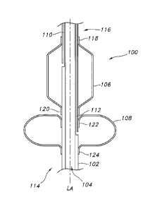
FIG. 1 is a side cross-sectional view illustrating an exemplary dilation
device.
FIG. 2 is a side cross-sectional view illustrating a detail of an exemplary
dilation device.
FIG. 3 is a side cross-sectional view illustrating the position of an
exemplary
dilation device pulled through the lumen wall and abdominal wall prior to
inflation of
the device.
FIGS. 4A and 4B are side cross-sectional views an exemplary dilation
device showing an inflated dilation balloon and inflated retention stabilizing
the
lumen wall against the abdominal wall.
DETAILED DESCRIPTION
Reference will now be made in detail to one or more embodiments,
examples of which are illustrated in the drawings. It should be understood
that
features illustrated or described as part of one embodiment may be used with
another embodiment to yield still a further embodiment.
Turning now to the drawings, there is shown at FIG. 1 in side, cross-
sectional view, an exemplary stoma dilation device 100 that includes a tubular
CA 02811308 2013-03-13
WO 2012/042475 PCT/1B2011/054253
8
support 102 defining at least one continuous pathway 104 through the device.
The
continuous pathway is configured to accommodate a guide wire.
The tubular support 102 has a length, width and a longitudinal axis "LA".
The tubular support 102 should be flexible but not too flexible as to readily
collapse
or kink when pressure is applied radially or axially. The width of the tubular
support
lo should be sufficiently small that it may fit in the working channel of
an endoscope.
For example, the tubular support may have a width of from about 0.2 to about 2
millimeters. More desirably, the tubular support may have a width of from
about
0.5 to about 1.75 millimeters. The tubular support may be made of a variety of
suitable materials. Exemplary materials include thermoplastic polyurethanes
such
as TECOFLEX medical-grade aliphatic polyether polyurethanes available from
Lubrizol Advanced Materials, Inc., Thermedics TM Polymer Products, Wilmington,
Massachusetts.
At least one inflatable dilation balloon 106 and at least one inflatable
retention balloon 108 is located on the tubular support. Each retention and
dilation
balloon has at least one characteristic dimensional shape or "cross section"
and at
least one characteristic "diameter" that is referenced orthogonally to the
longitudinal axis LA. The dilation balloon 106 has at least one dilation
balloon
inflation lumen 110 to inflate and deflate the dilation balloon. The retention
balloon
108 has at least one retention balloon inflation lumen 112 to inflate and
deflate the
retention balloon. Desirably, the inflation lumens are integrated in the
tubular
support 102. In this regard, the tubular support 102 may define multiple
lumens.
That is, the tubular support may define a continuous pathway 104, at least one
dilation balloon inflation lumen 110 to inflate and deflate one or more
dilation
balloons 106, and at least one retention balloon inflation lumen 112 to
inflate and
deflate one or more retention balloons 108. It is contemplated that the
inflation
lumens may be separated from the tubular support and be in the form of pilot
tubes
or the like.
Referring now to FIG. 2 of the drawings, there is illustrated in side cross-
sectional view an alternative inflation lumen configuration. In this
configuration, a
single inflation lumen is separated or divided by a plug "P" into a one
dilation
balloon inflation lumen 110 and one retention balloon inflation lumen 112. In
such
CA 02811308 2013-03-13
WO 2012/042475 PCT/1B2011/054253
9
a configuration, the dilation balloon may be inflated from the distal end of
the
device and retention balloon may be inflated from a proximal end of the device
that
may extend through an endoscope or other device.
Referring again to FIG. 1, the dilation device has a proximal end 114 and a
distal end 116. Generally speaking, the inflatable dilation balloon 106 forms
at
least a first portion of the device and the inflatable retention balloon 108
forms at
least a second portion of the device. For example, the dilation balloon 108 is
located towards the distal end 116 and the retention balloon is located
towards the
proximal end 114.
According to the invention, the inflatable retention balloon 108 is configured
to have an effective cross section upon full, unrestrained inflation that is
greater
than the largest cross section of the inflatable dilation balloon 106 upon
inflation as
is generally illustrated in FIG. 1. The dilation balloon(s) has a length and a
circular
cross section with a pre-determined diameter along the length upon full
inflation to
fit a specific sized catheter tube device. Alternatively, the dilation
balloon(s) may
be dilated to various effective diameters using respectively different
inflation
pressures to fit various catheter tubes. As a non-limiting example, the
effective
inflated diameter of the dilation balloon may range from about 3 to about 10
millimeters. As another non-limiting example, the effective inflated diameter
of the
dilation balloon may range from about 2 to about 8 millimeters. An inflated
dilation
balloon with a length and with a non-circular cross section along the length,
e.g.
elliptical or oval, is also contemplated.
The proximal section of the device (that portion of the dilation device that
is
positioned in the non-vascular lumen) incorporates at least one retention
balloon
(also referred to as the "proximal retention balloon") having a substantially
larger
cross section or diameter than any diameters of the dilation balloon(s).
Generally
speaking, the retention balloon may have a cross section or diameter that is
about
1.5 times to about 3 times the diameter of the dilation balloon. Once this
retention
balloon is inflated, it functions to stabilize the wall of the lumen and/or
provide
retention of the dilation device within the non-vascular lumen (e.g., the
stomach).
The proximal retention balloon 108 may have a circular or a non-circular cross
section as long as it is able to function as described above. The retention
balloon
CA 02811308 2013-03-13
WO 2012/042475 PCT/1B2011/054253
5 may have or lack a cross section with one axis of symmetry. For example,
the
proximal retention balloon 108 may have a square, rectangular, triangular,
elliptic,
oval or other shape. Alternatively and/or additionally the proximal retention
balloon
108 may incorporate lobes, fingers or projections that contribute to its
overall
cross-section so it is greater than the diameter of the dilation balloon 106.
10 Each balloon desirably includes two opposing open ends. The open ends
may be attached to the tubular support. Referring to FIG. 1, the dilation
balloon106 may have open ends 118 and 120. The retention balloon 108 may
have open ends 122 and 124. Desirably, the balloons are located as close
together as possible. In this regard, the open end 122 of the retention
balloon 108
may be inverted to provide a closer fit to the dilation balloon 106. It is
contemplated that the open end 120 of the dilation balloon 106 may also be
inverted to provide a close fit.
The retention balloon component and the dilation balloon may be formed of
materials such that the balloons are compliant, semi-compliant, or non-
compliant.
That is, the balloon may be relatively elastic (e.g., compliant) so that it
stretches as
well as expands upon inflation. The balloon may also be somewhat elastic
(e.g.,
semi-compliant) so that it or expands but has limited stretch upon inflation.
The
balloon may be inelastic (e.g., non-compliant) so that it expands without
significant
stretch upon inflation. The balloons may each be made of a different material
such that one may be compliant and one may be non-compliant. Various
combinations are contemplated. Desirably, one or both of the balloons may be
formed of polyurethane material identified as Pellethane0 2363-90A, available
from Lubrizol Advanced Materials, Inc., Thermedics TM Polymer Products.
According to an aspect of the invention, the dilation devices includes a
tubular support having a length, width and a longitudinal axis, the tubular
support
defining a continuous pathway through the device. The device further includes
at
least two inflatable balloons, at least a first balloon oriented axially on
the tubular
support forming a dilation region of the device and at least a second balloon
forming a retention region defining a second portion of the device. At least
one
balloon inflation lumen is provided for each inflatable balloon such that the
retention region is configured to have at least one effective cross section
and/or
CA 02811308 2013-03-13
WO 2012/042475 PCT/1B2011/054253
11
diameter upon full, unrestrained inflation that is greater than the largest
cross
section and/or diameter of the dilation region upon inflation.
As illustrated in FIG. 1, the dilation balloon 106 is a first balloon oriented
axially on the tubular support 102. The retention balloon 108 may desirably be
oriented axially on the tubular support 102. However, other configurations are
contemplated. For example, multiple retention balloons may be attached to the
tubular support to project radially from the tubular support.
The present invention also covers a system for dilating a stoma and
inserting a non-vascular catheter tube, the system includes a stoma dilation
device
as described above. The system also includes a non-vascular catheter tube
configured to fit over the fully or partially inflated dilation balloon
through the dilated
stoma tract and into the portion of the non-vascular lumen stabilized by the
retention balloon. According to the system, the stoma dilation device is
configured
to be deflated and at least a portion of the device withdrawn through the non-
vascular catheter tube.
In an exemplary and non-limiting description of a placement of the device,
an endoscope may be advanced into a non-vascular lumen (e.g., the stomach) to
insufflate and allow palpation to locate a catheter tube location site (e.g.,
a PEG
location site). Once the site is located, a needle may be inserted into the
stomach
through the abdomen and a guide wire may be introduced into the stomach
through the needle.
Standard endoscopic forceps, an endoscopic snare, or a balloon
attachment fixture may be inserted through the working channel of the
endoscope.
The forceps, snare or fixture is used to grasp the guide wire and the guide
wire is
pulled up through the working channel of the endoscope and out of the
patient's
Muth.
A dilation device with its attached inflation lumen is secured to the end of
the guide wire and is pulled through the working channel of the endoscope
using
the guide wire and into the stomach. The dilation device may have a dilation
balloon having a pre-determined volume and diameter upon full inflation and a
retention balloon having a diameter upon full inflation that is greater than
the
largest diameter of the dilation balloon. When these balloons are in a folded
or
CA 02811308 2013-03-13
WO 2012/042475 PCT/1B2011/054253
12
tightly wrapped state, the dilation device has an overall diameter that fits
within the
working channel of the endoscope. Typically, the diameter is in the range of
about
2 millimeters or less.
The needle is removed from the stomach, while retaining the guide wire in
the needle tract. The dilation device is pulled up into and partially through
the
needle tract so that it reaches the abdominal tissue and the skin on the
exterior of
the patient as illustrated in FIG. 3.
Referring now to FIGS. 4A and 4B, the dilation balloon 106 of the dilation
device 100 is then inflated by gradually introducing controlled amounts of
fluid
(e.g., liquid or gas) to increase pressure in the balloon so it smoothly and
gradually
expands the needle tract into a stoma tract. The retention balloon 108 of the
dilation device 100 is also then inflated by gradually introducing controlled
amounts
of fluid (e.g., liquid or gas) to increase pressure in the balloon so it
smoothly and
gradually expands. When the retention balloon 108 becomes larger than the
dilation balloon 106 and expands to full inflation, it stabilizes the stomach
wall
"SW" by bringing it up against the wall of the abdomen "AW" as illustrated in
FIG.
4B. According to an aspect of the invention, the fully inflated diameters of
this
balloon may be selected from a range to match the diameter of the catheter
tube
device (e.g., the PEG device) that will be inserted. The dilation device can
have
two different balloons in series; a dilation balloon (desirably non-compliant)
that is
positioned distally, and a separate retention balloon (that may also be non-
compliant) that is positioned proximally. An example of a dilation device with
a
non-compliant balloon and a separate retention balloon has the separate
retention
balloon affixed to a proximal part of the dilation device to help retain the
device in
the patient's stomach and the non-compliant balloon, which is smaller than the
separate retention balloon when both are fully inflated, is affixed distally
and the
non-compliant balloon is used to expand the needle tract into a stoma tract.
After the dilation device has its affixed balloons fully inflated, a peel-away
sheath is placed over the distal-most portion of the dilation device (i.e.,
from the
outside of the patient). The dilation balloon of the dilation device is
partially
deflated a small amount to allow the peel-away sheath to pass over the distal
end
CA 02811308 2013-03-13
WO 2012/042475 PCT/1B2011/054253
13
of the dilation device and dilation balloon and through the stoma tract into
the
stomach.
Next, the dilation device has its balloons completely deflated. Because it is
still attached to the guide wire, the dilation device may be removed through
the
working channel of the endoscope by withdrawing the guide wire through the
working channel of the endoscope. Alternatively, the dilation device can be
removed by cutting off the syringe inflation connector from the inflation
lumen at
the mouth (if such an inflation lumen is used) and pulled through the stoma
site via
the sheath. It is noted that the different inflation lumen configurations for
the
dilation device are illustrated in FIGS. 1 and 2.
A catheter tube (e.g., a PEG device) is then threaded over the guide wire
and the distal end of PEG device is inserted through the peel away sheath. The
peel-away sheath is separated and removed from the stoma tract, any other
placement tools are removed, and a retainer on the distal, in-dwelling end of
the
PEG device hold the PEG device in place.
Alternatively, a catheter tube may be put into position without the use of a
peel-away sheath. After the dilation device has its affixed balloons fully
inflated,
the dilation balloon of the dilation device is deflated by only a small amount
to
allow the catheter tube to pass over the distal end of the dilation device and
through the stoma tract into the stomach.
Next, the dilation device has its balloon or balloons completely deflated.
Because it is still attached to the guide wire, the dilation device may be
removed
through the working channel of the endoscope by withdrawing the guide wire
through the working channel of the endoscope. Alternatively, the dilation
device
can be removed by cutting off the syringe inflation connector from the
inflation
lumen at the mouth (if such an inflation lumen is used) and pulled through the
stoma site via the catheter tube. It is noted that the different inflation
lumen
configurations for the dilation device are illustrated in FIGS. 1 and 2.
While the present invention has been described in connection with certain
preferred embodiments it is to be understood that the subject matter
encompassed
by way of the present invention is not to be limited to those specific
embodiments.
On the contrary, it is intended for the subject matter of the invention to
include all
CA 02811308 2013-03-13
WO 2012/042475 PCT/1B2011/054253
14
alternatives, modifications and equivalents as can be included within the
spirit and
scope of the following claims.