Note: Descriptions are shown in the official language in which they were submitted.
CA 02811331 2016-09-16
1
SUTURE ANCHOR AND METHOD FOR FIXATING A SUTURE RELATIVE
TO HARD TISSUE
FIELD OF THE INVENTION
The invention is in the field of medical technology and concerns a suture
anchor and
a method for fixating a suture relative to hard tissue, in particular with the
aim of
attaching soft tissue to the hard tissue with the aid of the suture, wherein
the hard
tissue is in particular bone tissue of a human or animal patient.
BACKGROUND
The publications US 7008226, WO 2009/109057 and WO 2009/055952 (all to
Woodwelding) disclose devices and methods for attaching a suture to hard
tissue
with the aid of a suture anchor, wherein the suture anchor comprises a
material
having thermoplastic properties and is anchored in a hard tissue opening with
the aid
of preferably vibratory energy used for in situ liquefaction of the material
having
thermoplastic properties. The liquefied material penetrates into pores or
other
suitable structures of the hard tissue of the wall of the hard tissue opening,
where on
re-solidification it constitutes a positive fit connection between the hard
tissue and
the suture anchor. The anchor comprises the material having thermoplastic
properties
on a circumferential surface or in the form of a thermoplastic sleeve and it
is
liquefied when the anchor is forced into the hard tissue opening and
simultaneously
vibrated or when the anchor or part thereof is positioned in the hard tissue
opening
and the thermoplastic sleeve is held between a vibrating tool and a counter
element.
The suture is threaded through the proximal or distal end of the suture
anchor.
- 2 -
Further suture anchors and methods for fixating sutures to hard tissue are
disclosed in
the publications US-7678134, US-7695495, US-2006/161159, US-2009/192546, US-
2009/187216 (all to Arthrex), US-5733307 (Dinsdale), or US-6508830 (Steiner),
wherein the disclosed anchors comprise an interference screw to be screwed
into a
bone opening provided for the purpose, or a plug preferably made of bone
material
and to be press-fitted into a bone opening provided for the purpose, wherein
the suture
is either held by the screw or plug or by an additional element being retained
in the
opening with the aid of the screw or plug.
Methods of anchoring an item in an opening provided in hard tissue, e.g. in
bone tissue
of a human or animal patient with the aid of a material having thermoplastic
properties
which is liquefied in situ and made to penetrate the hard tissue of the wall
of the
opening are furthermore disclosed in the publications US-7335205, US-
2006/0105295, US-2008/109080, US-2009/131947, WO-2009/109057, and WO-
2009/132472. Therein preferred energy used for the liquefaction is mechanical
vibration energy.
SUMMARY OF EMBODIMENTS OF THE INVENTION
In accordance with an aspect of at least one embodiment, there is provided a
suture
anchor for locking a suture relative to a hard tissue, the suture anchor
comprising a pin
portion, a material having thermoplastic properties being arranged at least
partly
around a pin portion circumference and, for holding the suture, a suture
conduit at a
distal end of the pin portion, wherein, for locking the suture relative to the
hard tissue,
a suture groove extending in axial direction along the pin portion comprises a
zero
depth portion at a proximal end of the pin portion, wherein the suture conduit
at the
distal end of the pin portion is an undercut groove extending across a distal
face of the
pin portion.
CA 2811331 2019-09-17
- 2a -
In accordance with an aspect of at least one embodiment, there is provided a
suture
anchor for locking a suture relative to a hard tissue, the suture anchor
comprising a pin
portion, a material having thermoplastic properties being arranged at least
partly
around a pin portion circumference and, for holding the suture, a suture
conduit at a
distal end of the pin portion, wherein, for locking the suture relative to the
hard tissue,
the suture conduit in the distal end is collapsible and wherein the distal end
comprises
a collapsible anchor portion adjoining the suture conduit and comprising the
material
having thermoplastic properties to be softened and thereby weakened on
application
of the liquefaction energy.
CA 2811331 2019-09-17
CA 02811331 2016-09-16
3
In accordance with an aspect of at least one embodiment, there is provided a
kit of
parts comprising: a suture anchor and a vibration tool, the vibration tool
being
suitable for fixating the suture anchor in a hard tissue opening by
positioning a distal
tool face against a proximal anchor face and transmitting a pushing force and
mechanical vibration from the vibration tool to the suture anchor, wherein the
proximal anchor face comprises at least one mouth of a suture groove extending
in
an axial direction along a circumferential surface of the suture anchor, and
wherein
the distal tool face and the proximal anchor face are adapted to each other
such that
the distal tool face does not cover the at least one mouth comprised by the
proximal
anchor face, when the distal tool face is positioned against the proximal
anchor face
for the fixation process.
In accordance with an embodiment, provided is a suture anchor and a method for
fixating the suture anchor in a hard tissue opening with the aid of a material
having
thermoplastic properties, which is liquefied in situ to penetrate the hard
tissue of the
wall of the hard tissue opening. The suture anchor and the method are to be
suitable
for attaching soft tissue to the hard tissue with the aid of the suture, and
the hard
tissue is to be in particular bone tissue of a human or animal patient. The
suture is
preferably fixated relative to the suture anchor or the hard tissue
respectively in a
non-slideable manner (suture locking), wherein suture tension may be
adjustable
during at least an initial section of the fixation process. However, the
suture anchor
may also serve for establishing a slideable suture fixation. The method
including
suture locking is in particular suitable for per se known knot-less procedures
for
suturing soft tissue to hard tissue. Furthermore, the suture anchor and method
are to
be capable of safeguarding the suture against undesired influence caused by
the in-
situ liquefaction (i.e., in the case of liquefaction through mechanical
vibration,
against undesired influences of friction and heat), and to therefore allow use
in
connection with friction and/or heat sensitive sutures. Furthermore, a distal
end of
the anchor may be equipped for enhancing retention of the suture anchor in the
hard
tissue opening, in particular in hard tissue with only little mechanical
stability.
CA 02811331 2016-09-16
4
In an embodiment the suture anchor comprises a material having thermoplastic
properties at least on surface portions to be in contact with the hard tissue
in the hard
tissue opening or preferably it consist fully of such a material, wherein at
least part of
the material having thermoplastic properties is liquefied in situ and
penetrates the
hard tissue of the walls of the opening. The distal suture end comprises a
suture
conduit for holding the suture, e.g. a distal suture groove, a suture channel
or an
eyelet, of more than one such conduit or a combination of different ones of
such
conduits. The suture anchor is designed in particular for locking the suture
relative to
the anchor in a last phase of the process of fixating the anchor in the hard
tissue,
wherein the locking of the suture is achieved either by clamping the suture
between
the anchor and the hard tissue in the hard tissue opening or by braking or
clamping it
through collapse of the suture conduit or suture conduits. This means that the
locking
of the suture does principally not depend on the fixation process in which the
suture
anchor is fixated or anchored in the hard tissue opening, which allows
safeguarding
the suture against possibly damaging influences of the liquefaction process
(heat,
vibration) and/or allows adjustment of the suture tension during or possibly
even
after the anchoring process.
Furthermore, the suture anchor may comprise structures preferably in a distal
end
portion which structures are capable of being spread or radially expanded by
suture
tension and/or abutment of the distal anchor end against the bottom of a blind
opening, which spreading or expanding enhances retainment in or beyond the
hard
tissue opening. The named spreading is e.g. effected during the liquefaction
process
by the tensioned suture being forced against or into the anchor material
proximal to
the suture conduit when this anchor material is mechanically weakened by
absorption
of heat, which may result in distal anchor sections to be forced apart such
spreading
the distal anchor portion. In a further embodiment a portion of the anchor is
designed
to be collapsible under a compressive load and can therewith be radially
expanded
e.g. under the influence of the suture tension.
CA 02811331 2016-09-16
For the fixation process, for which mechanical vibration energy (in particular
ultrasonic vibrational energy) is preferably used, the suture anchor is forced
into the
hard tissue opening and simultaneously the liquefaction energy is transmitted
into the
material to be liquefied. For this purpose, a tool suitable for transmitting a
pushing
5 force and the vibrational energy to the anchor is used, a distal end of
the tool being
preferably attached to the proximal face of the suture anchor and a proximal
end of
the tool being coupled to a vibration source. This fixation process does not
necessitate any rotation of the suture anchor, i.e. the suture anchor is not
screwed into
the hard tissue opening and therefore preferably does not comprise a screw
thread.
The vibration source is in particular a source of ultrasonic vibration (e.g.
piezoelectric vibration generator possibly comprising a booster to which the
tool is
coupled) and the tool is suitable for transmission of the vibration from its
proximal
end to its distal face, preferably such that the distal face vibrates with a
maximal
longitudinal amplitude. For the in situ liquefaction the distal face of the
tool is
applied to the proximal face of the suture anchor. It is possible also to
activate the
tool to vibrate in a radial or in a rotational direction.
Alternatively, the energy source may be a laser, preferably emitting laser
light in the
visible or infrared frequency range and the tool is equipped for transmitting
this light
to its distal end, preferably via glass fiber. For the in situ liquefaction
the laser light
is absorbed near the distal tool face or in the suture anchor, wherein in the
latter case
the material having thermoplastic properties comprised by the suture anchor
may
contain particles or substances effecting such absorption. Furthermore, the
energy
source may be a source of electric energy which e.g. heats an electric
resistor in a
distal tool portion or which causes eddy currents and therewith thermal energy
near
the distal tool face or in the suture anchor.
CA 02811331 2016-09-16
6
Suitable in situ liquefaction of a material having thermoplastic properties
with the aid
of vibration energy combined with an acceptable thermal loading of the tissue
and
suitable mechanical properties of the positive fit connection to be produced
is
achievable by using materials with thermoplastic properties having an initial
modulus of elasticity of at least 0.5 GPa and a melting temperature of up to
about
350 C in combination with vibration frequencies preferably in the range of
between
2 and 200 kHz (preferably 15 to 40 kHz, or even more preferably between 20 and
30
kHz). The modulus of elasticity of at least 0.5 GPa is in particular necessary
if the
material having thermoplastic properties is to transmit the vibration without
loss of
mechanical stiffness.
Non-limiting examples of materials having thermoplastic properties suitable
for the
suture anchor are thermoplastic polymers, e.g.: resorbable or degradable
polymers
such as polymers based on lactic and/or glycolic acid (PLA, PLLA, PGA, PLGA
etc.) or polyhydroxy alkanoates (PI IA), polycaprolactone (PCL).
polysaccharides,
polydioxanes (PD) polyanhydrides, polypeptides or corresponding copolymers or
composite materials containing the named polymers as a component; or non-
resorbable or non-degradable polymers such as polyolefines (e.g.
polyethylene),
polyacrylates, polymetacrylates, polycarbonates, polyamides,
polyester,
polyurethanes, polysulfones, polyarylketones, polyimides, polyphenylsulfides
or
liquid crystal polymers LCPs, polyacetales, halogenated polymers, in
particular
halogenated polyolefines, polyphenylensulfides, polysulfones, polyethers or
equivalent copolymers or composite materials containing the named polymers as
a
component.
Specific embodiments of degradable materials are Polylactides like LR706
PLDLLA
70/30 (e.g. filled with up to 30% biphasic calciumphosphate), R208 PLDLA
50/50,
L2 1 OS, and PLLA 100% L, all of Bohringer. A list of suitable degradable
polymer
materials can also be found in: Erich Wintermantel und Suk-Woo Haa,
CA 02811331 2016-09-16
7
"Medizinaltechnik mit biokompatiblen Materialien und Verfahren", 3. Auflage,
Springer, Berlin 2002 (in the following referred to as "Wintermantel"), page
200; for
information on PGA and PLA see pages 202 ff., on PCL see page 207, on PHB/PHV
copolymers page 206; on polydioxanone PDS page 209. Discussion of a further
bioresorbable material can for example be found in CA Bailey et al., J Hand
Surg [Br]
2006 Apr;31(2):208-12.
Specific embodiments of non-degradable materials are Polyetherketone (PEEK
Optima,
Grades 450 and 150, lnvibio Ltd), Polyetherimide, Polyamide 12, Polyamide 11,
Polyamide 6, Polyamide 66, Polycarbonate,
Polymethylmethacry late,
Polyoxymethylene. or polycarbonate-urethane (e.g. Bionate by DSM, in
particular types
65D and 751)). An overview table of polymers and applications is listed in
Wintermantel. page 150; specific examples can be found in Wintermantel page
161 ff.
(PE, Hostalen Gur 812, HOchst AG), pages 164 ff. (PET), 169ff. (PA, namely PA
6 and
PA 66), 171 ff. (PTFE), 173 ff. (PMMA), 180 (PUR, see table), 186 ff. (PEEK),
189 ff.
(PSU), 191 ff (POM ¨ Polyacetal, tradenames Delrin, Tenac, has also been used
in
endoprostheses by Protec).
The material having thermoplastic properties may further contain foreign
phases or
compounds serving further functions. In particular, the thermoplastic material
may be
strengthened by admixed fibers or whiskers (e.g. of calcium phosphate ceramics
or
glasses) and such represent a composite material. The material having
thermoplastic
properties may further contain components which expand or dissolve (create
pores) in
situ (e.g. polyesters, polysaccharides, hydrogels, sodium phosphates),
compounds
which render the implant opaque and therewith visible for X-ray, or compounds
to be
released in situ and having a therapeutic effect, e.g. promotion of healing
and
regeneration (e.g. growth factors, antibiotics, inflammation inhibitors or
buffers such as
sodium phosphate or calcium carbonate against adverse effects of acidic
decomposition). If the thermoplastic material is resorbable, release of such
compounds
CA 02811331 2016-09-16
8
is delayed. If the device is to be anchored not with the aid of vibration
energy but with
the aid of electromagnetic radiation, the liquefiable material having
thermoplastic
properties may locally contain compounds (particulate or molecular) which are
capable
of absorbing such radiation of a specific frequency range (in particular of
the visible or
infrared frequency range), e.g. calcium phosphates, calcium carbonates, Sodium
phosphates, titanium oxide, mica, saturated fatty acids, polysaccharides,
glucose or
mixtures thereof
Fillers used may include degradable, osseostimulative fillers to be used in
degradable
polymers, including: 13-Tricalciumphosphate (TCP), Hydroxyapatite (HA, <90%
crystallinity); or mixtures of TCP, HA, DHCP, Bioglasses (see Wintermantel).
Osseo-
integration stimulating fillers that are only partially or hardly degradable,
for non
degradable polymers include: Bioglasses, Hydroxyapatite (>90% cristallinity),
HAPEX , see SM Rea et al., J Mater Sci Mater Med. 2004 Sept;15(9):997-1005;
for
hydroxyapatite see also L. Fang et al., Biomaterials 2006 Jul; 27(20):3701-7,
M. Huang
et al., J Mater Sci Mater Med 2003 Jul;14(7):655-60, and W. Bonfield and E.
Tanner,
Materials World 1997 Jan; 5 no. 1:18-20. Embodiments of bioactive fillers and
their
discussion can for example be found in X. Huang and X. Miao, J Biomater App.
2007
Apr; 21(4):35I-74), JA Juhasz et al. Biomaterials, 2004 Mar; 25(6):949-55.
Particulate
filler types include: coarse type: 5-20um (contents, preferentially 10-25% by
volume),
sub-micron (nanofillers as from precipitation, preferentially plate like
aspect ratio > 10,
10-50 am, contents 0.5 to 5% by volume). Experiments show that liquefaction
with the
aid of ultrasonic vibration energy allows filling the thermoplastic polymer to
a relatively
high degree without impairing the capability of the liquefied material to
penetrate
structures as e.g. the trabecular structure of viable cancellous hone.
.. The suture anchor may in addition to the material having thermoplastic
properties also
comprise portions (e.g. a core) of material having no thermoplastic properties
or
thermoplastic properties which are not suitable for in situ liquefaction under
the
CA 02811331 2016-09-16
9
conditions of the fixating process (non-liquefiable materials). Such portions
may consist
of any suitable material (e.g. polymer, metal, ceramic, glass) which may be
bio-
resorbable or not bio-resorbable. Non-bioresorbable or non-biodegradable such
portions may comprise surfaces equipped for furthering osseointegration (e.g.
per se
known surface structures or coatings) where in contact with the bone tissue,
in
particular if the material having thermoplastic properties is bio-resorbable
or bio-
degradable and therefore the anchoring function needs to be gradually taken
over by
osseointegration. Suitable non-liquefiable materials, which are bio-
resorbable, are
e.g. polylactic acid (PLA) filled with Hydroxyapatite or calciumphosphates, in
particular PLLA filled with 60% tricalciurnphosphate.
The vibration tool can be designed very slim and approximately 200 mm long or
even longer. Therefore the suture anchor and method are in particular suitable
for
minimally invasive surgery but are also applicable in open surgery. The
vibration
tool preferably has a length corresponding to half of the vibration wavelength
in the
tool material or of this half wavelength multiplied with an integer factor,
the
theoretical half wavelength e.g. for a tool made of titanium grade 5 and for a
vibration frequency of 20 kHz being 126.5 mm, for a vibration frequency of 25
kHz
101.2 mm.
Device and method according to at least one embodiment of the invention as
above
described are in particular applicable for substantially all surgical
procedures in a
human or animal patient, in which surgical procedure a suture needs to be
attached to
hard tissue and locked relative to the latter, some of the embodiments being
in
particular advantageous in hard tissue of only little mechanical strength. In
the same
manner, the suture anchor and the method are applicable for attaching a suture
to a
replacement material having features comparable to the features of hard
tissue, or to
part hard tissue part replacement material or to a further implant (e.g.
endoprosthesis)
wherein the implant needs to be suitably equipped, e.g. with undercut
openings.
CA 02811331 2016-09-16
Examples of such applications are the fixation of a soft tissue (in particular
ligament,
tendon or cartilaginous tissue) to bone tissue in a so called knot-less single
row
procedure, e.g. fixation of a rotator cuff to underlying bone tissue (or a
corresponding endoprosthesis), Achilles tendon repair, reattachment of the
acetabular
5 labrum to the acetabulum or the glenoid labrum to the scapula or, as
lateral anchors
in a so called double row procedure (see Fig. I). In the latter case it is
advantageous
to use the same fixation process for, fixation of the anchors (without the
suture
locking) of the medial row also. Preferred devices and methods for fixating
such
medial anchors are e.g. disclosed in a co-pending application claiming the
same
10 priority. However, the suture anchor and the method according to at
least one
embodiment may also be used for slideablc attachment of a suture to hard
tissue (e.g.
for the medial anchors in a double row procedure).
Further exemplary applications of the anchor and method are e.g. regarding the
human shoulder joint: the Bankart repair or the repair of SLAP-lesions
(superior
labrum anterior to posterior), regarding the human hand: the UCL-repair (ulnar
collateral ligament) as treatment for "skier's thumb" (acute condition) or
-gamekeeper's thumb" (chronic condition), the SL-reconstruction (scapholunate
ligament), the TFCC-repair (triangular fibrocartilagecomplex), or the capsular
reattachment of the metacarpophalangeal joint, regarding the human elbow:
ulnar
collateral ligament reconstruction (Tommy John surgery), regarding the human
foot:
the Bromstrom repair, the peroncal retinacular repair or halux valgus
reconstruction,
and regarding the human knee: iliotibial band tenodesis. Generally speaking,
the
suture anchor and method are particularly advantageously applicable in repair
surgery regarding ligaments in the human hand and wrist (ligaments of
interphalangcal, metaphalangeal and carpometaphalangeal joints and carpal
ligaments) and in the human foot and ankle joint.
CA 02811331 2016-09-16
II
BRIEF DESCRIPTION OF THE DRAWINGS
The suture anchor and the method according to the invention are described in
further
detail in connection with the appended Figs., wherein:
Fig. 1 illustrates four successive phases of the per se known
double row procedure using the example of a rotator cuff
repair, in which procedure the anchor according . to an
embodiment of the invention preferably constitutes the
anchors of the lateral row but possibly also the anchors of
the medial row;
Fig. 2 shows an exemplary embodiment of the suture anchor
according to the invention, the suture anchor being
suitable for locking the suture between the hard tissue and
the suture anchor;
Fig. 3 shows a further exemplary embodiment of the suture
1 5 anchor according to the invention, the suture anchor being
suitable for locking the suture by collapsing the suture
conduit;
Figs. 4 to 6 show further and alternative features applicable for the
suture anchors shown in Figs. 2 and 3;
Fig. 7 shows in detail the distal end of an exemplary vibration
tool suitable for fixation of the suture anchor according to
Fig. 6;
CA 02811331 2016-09-16
12
Figs 8 to 12 show further exemplary embodiments of distal ends for
suture anchors according to the invention which are e.g.
suitable for fixation in hard tissue of only little mechanical
stability.
DETAILED DESCRIPTION OF THE DRAWINGS
Figure 1 illustrates the per se known double row procedure for suturing a soft
tissue
to a hard tissue, using the example of reattaching a torn rotator cuff tendon
10 to
humeral bone tissue 11 (or a corresponding endoprosthesis) in four successive
phases
(a), (b), (c) and (d). Phase (a) is before the repair operation and shows the
location 12
.. in which reattachment is necessary. In phase (b) two medial anchors 13 are
anchored
in the bone tissue, in locations to eventually be located underneath the
tendon 10,
each one of the medial anchors 13 attaching at least one suture 4 to the bone
tissue in
a slideable manner. In phase (c) the end sections of each suture attached to
one of the
medial anchors is passed through the torn tendon 1() and by tensioning the
sutures
away from the tendon end (not shown), the latter is pulled over the medial
anchors
13. In phase (d) two lateral anchors 14 are anchored in the bone tissue just
beyond
the edge of the tear, the row of lateral anchors 14 running about parallel to
the row of
medial anchors 13, the end sections of the sutures 4 being tensioned and
locked with
the aid of the lateral anchors 14 in a cross-wise manner, such that the two
suture end
sections held by one medial anchor 13 are locked by two different lateral
anchors 14
such forming crossed suture bridges 15 between the row of medial anchors 13
and
the row of lateral anchors 14. Therein each row of anchors may comprise two or
more than two anchors and each medial anchor 13 is used for attaching at least
one
suture 4 (two suture end portions) and each lateral anchor 14 is used for
locking at
least two suture end portions originating from two different medial anchors
13.
CA 02811331 2016-09-16
13
As already mentioned further above, the suture anchor and the method according
to
at least an embodiment of the invention are in particular advantageously
applicable
in the lateral row but correspondingly adapted are also applicable in the
medial row.
Figures 2 and 3 illustrate exemplary embodiments of the suture anchor
according to
the invention. These suture anchors 2 comprise a material having thermoplastic
properties (liquefiable material) or they are preferably made of such a
material and
they are anchored in a hard tissue opening by in situ liquefaction of at least
part of
the material having thermoplastic properties and by making the liquefied
material to
flow into the hard tissue to constitute, when re-solidified, a positive fit
connection
between the anchor and the hard tissue. The anchoring method on which the
anchors
according to an embodiment the invention are based is disclosed e.g. in the
publication US-7335205 the disclosure of which is enclosed herein in its
entirety.
According to this method a proximal face of the anchor is contacted with a
tool
which transmits energy into the anchor, in particular a vibration tool which
transmits
vibrational energy. Simultaneously the anchor is pushed into a hard tissue
opening
having a cross section which is slightly smaller than the cross section of the
anchor
portion to be fixated in the opening, such that anchor portions comprising the
=
material having thermoplastic properties get into intimate contact with the
hard
tissue, which in the case of the use of vibrational energy serves also as
counter
.. element necessary for transforming the vibrational energy into friction
heat for the in
situ I iquefacti on.
Furthermore, the suture anchors according to Figs 2 and 3 comprise at least
one distal
suture conduit (e.g. distal groove, channel, or eyelet) in which the suture is
held
when the suture anchor is positioned relative to the hard tissue opening and
fixated
therein, and structures for locking the suture relative to the fixated anchor
or the hard
tissue respectively either by clamping it between the suture anchor and the
wall of
CA 02811331 2016-09-16
14
the hard tissue opening (Fig. 2) or by collapsing the suture conduit and such
braking
or clamping the suture threaded therethrough (Fig. 3).
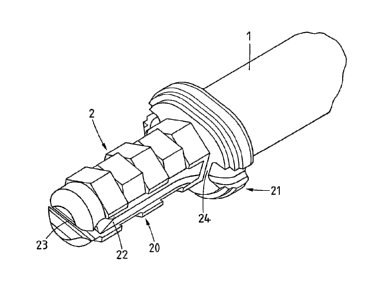
The suture anchor 2 as shown in Figure 2 comprises a pin portion 20 and
advantageously a head portion 21 and is shown attached to a tool 1, by e.g. a
press fit
connection between a tool protrusion reaching into a recess in the head
portion 21
(not shown). At least the pin portion 20 comprises at least at parts of its
lateral
surfaces the material having thermoplastic properties and advantageously, as
illustrated, energy directors e.g. in the form of axial edges extending over
part of the
pin length and being offset relative to each other in adjoining such part
lengths (the
.. pin portion has e.g. as illustrated the form of a stack of misaligned
polygon-shaped
discs). The head portion 21 may also comprise the material having
thermoplastic
properties and may also be anchored in the hard tissue, in which case the hard
tissue
opening provided for the anchor 2 will need to have a stepped form including a
narrower inner portion for accommodation of the pin portion 20 and a larger
outer
portion for accommodation of the head portion 21. Alternatively, the distal
face of
the head portion may be anchored in the hard tissue surface around the mouth
of the
opening provided for the pin portion.
The pin portion 20 comprises a suture groove 22 running across the distal pin
face
and, in axial direction, along two opposite pin sides, wherein the suture
groove 22
comprises at least one portion which is undercut, the undercut groove portion
23
being situated e.g. as illustrated, on the distal pin face (suture conduit).
Preferably,
the overall cross section of the suture groove 22 is adapted to the suture or
sutures to
be locked with the aid of the anchor such that the suture(s) running along the
groove
does not protrude from the groove, i.e. does not get into contact with the
hard tissue
when the pin portion 20 is pushed into the hard tissue opening provided
therefore
while being vibrated. This measure serves for preventing damage of a friction
and/or
heat sensitive suture on fixation of the anchor in particular when using
vibrational
CA 02811331 2016-09-16
energy for such fixation. When using a suture of no such sensitivity the
suture may
as well protrude from the suture groove and therewith rub on the wall of the
hard
tissue opening, wherein such friction may help to at least primary
stabilization of the
suture relative to the suture anchor.
5 The undercut portion 23 of the suture groove 22 is dimensioned such that
the suture
to be locked with the aid of the anchor can be entered into the undercut
groove by
resiliently deforming the groove entrance and that the suture is safely kept
in the
undercut groove portion 23 when no force acting perpendicular to the groove
length
pulls the suture out of the undercut groove portion 23.
10 The suture groove 22 continues on both sides of the head portion 21, but
at the
transition between pin and head portion comprises an interruption 24, i.e. it
has a
depth on a proximal end of the pin portion 20 which decreases with decreasing
distance form the head portion 21, a zero-depth portion (or portion which
relevantly
reduced depth) at the transition between the pin and the head portion, and a
depth on
15 a distal side of the head portion 21 which increases with increasing
distance from the
pin portion 20. This measure serves for clamping the suture between the hard
tissue
and the implanted anchor for locking it.
The head portion 21 has a larger cross section than the distal end of the tool
1 such
that, when the anchor 2 is attached to this distal tool end, the proximal face
of the
head protrudes beyond the distal face of the tool at least on those two sides
on which
the suture groove reaches this proximal head face. As illustrated, the distal
tool end
may have a circular cross section and the head portion an oval cross section
having a
smaller diameter which is the same as the tool diameter and a larger diameter
spanning between the mouths of the suture grooves. This measure serves for
preventing a friction and/or heat sensitive suture from contact with the tool
1, in
CA 02811331 2016-09-16
16
particular with the edge of the distal tool face, which is particularly
advantageous
when the tool is a vibration tool and the suture is of a friction and/or heat
sensitive
type.
For fixating a suture relative to hard tissue using the anchor 2 as
illustrated in Fig. 2,
.. a hard tissue opening is provided, a cross section of at least an inner
portion of the
hard tissue opening being adapted to the pin portion 20 of the anchor 2 such
that a
distal end of the pin portion 20 having the smallest cross section fits easily
into the
opening but the rest of the pin portion 20 can be introduced into the opening
using a
pressing force only. The pin portion 20 of the anchor which is attached to the
tool
.. being coupled to an energy source (preferably vibration source) is
positioned into the
mouth of the opening, the suture to be fixated by the anchor running along the
suture
groove 22 and extending out of the hard tissue opening on both sides of the
anchor.
The pressing force is then applied to the suture anchor via the tool, the
desired suture
tension is established and the energy source is activated (tool and anchor
vibrated).
.. Where in intimate contact with the hard tissue wall of the opening the
material
having thermoplastic properties is liquefied and penetrates into the hard
tissue. At the
same time the anchor is pushed further into the opening and is finally
anchored when
the head portion 21 abuts the hard tissue surface or a step in the hard tissue
opening.
Only at the very end of the described anchoring process, the suture is clamped
between the hard tissue in the region of the mouth of the hard tissue opening
or the
step in the opening and the suture anchor at the transition from the pin
portion 20 to
the head portion 21, which transition location only then reaches the hard
tissue. This
means that the suture, if correspondingly adapted to the suture groove,
remains
slideable (possibly against some friction between suture and tissue inside the
hard
tissue opening) relative to the anchor during an initial part of the fixation
step and
therefore the suture tension can still be adapted or maintained up to when the
anchor
is very close to its final fixated position.
CA 02811331 2016-09-16
17
Further embodiments of the suture anchor as illustrated in Fig. 2 may e.g. not
comprise a head portion, comprise energy directors of a different type or no
energy
directors at all and/or may comprise a core not being made of the material
having
thermoplastic properties but comprising a sleeve of or being coated with the
latter at
.. least on the pin portion and possibly excepting the suture groove 22 and
the distal pin
end.
When used for locking sutures which are neither friction nor heat sensitive,
and
without the possibility of the late tension adjustment, the suture groove may
he
present at the distal face of the pin section 20 only (zero depth suture
groove portion
extending along the entire anchor length), where it may be undercut or may
have a
cross section dimensioned for holding the suture by friction. The same effect
can be
achieved with a suture anchor as shown in Fig. 2 and a suture having a cross
section
greater than the cross section of the suture groove 22 (possibly not having a
zero
depth portion at all), wherein the suture protrudes from the groove. For
achieving a
slideable attachment of the suture to the hard tissue using the suture anchor
according
to Fig. 2 or a similar suture anchor, a suture of a diameter smaller than the
reduced
depth of the zero-depth groove portion is used, or the anchor is introduced
into the
hard tissue opening only such that the zero-depth groove portion protrudes
from the
opening or the opening is provided with a mouth of a larger cross section to
accommodate the zero-depth groove portion without clamping the suture.
Furthermore, the head portion 21 may comprise a protrusion suitable for
attachment
of the anchor 2 to the tool I which has a corresponding recess in its distal
face.
Furthermore, the suture anchor according to Fig. 2, in particular the
embodiment
comprising a core of e.g. a metal may comprise a tapering or sharpened distal
end for
being able to be forced at least into cancellous bone without the necessity of
providing an opening therein beforehand or of providing such opening only
through
the cortical bone. The forcing of the suture anchor 2 into the bone tissue is
preferably
CA 02811331 2016-09-16
18
effected using the same tool as used for the anchoring step but without
transmitting
energy for the liquefaction to the suture anchor.
The anchor as illustrated in Figure 3 differs form the anchor as illustrated
in Fig. 2
mainly regarding the means provided for the suture locking, which in this case
are
.. located at the distal anchor end being equipped for holding the suture.
This distal end
has a smaller cross section than the rest of the anchor and comprises two
eyelets 25
(suture conduit) and it consists of a material which is plastically deformable
or
becomes plastically deformable under the influence of energy transmitted into
the
anchor for its fixation in the hard tissue such that a compressive load,
caused through
.. the suture tension and/or by abutment against a bottom wall of a blind hard
tissue
opening is able to collapse it (collapsible suture conduit). The suture 4 to
be fixated
and .locked with the aid of the anchor 2 is threaded through the two eyelets
75 and
runs along the anchor length e.g. in a suture groove as described further
above in
connection with Fig. 2, but not shown in Fig. 3.
The anchor 2 as illustrated in Fig. 3 is fixated in a hard tissue opening 5
much as
discussed above in connection with Fig. 2, wherein the distal pin end
comprising the
two eyelets 25 is made to collapse by the suture being tensioned against the
anchor
and/or by pushing it against the hard tissue on the bottom of the opening 5
provided
for the anchor 2, wherein by such collapse the suture 4 is locked due to its
bending
radius between the two eyelets 25 being reduced and therewith suture braking
increased ill such a manner that the suture cannot slide therethrough any more
and/or
due to the decreasing cross section of the eyelets 25 which causes the suture
4 to be
clamped. In such a case the zero-depth portion of the suture groove as above
described is not needed for securely locking the suture, which means that in
this
latter case, there may be no contact at all between the suture 4 and the hard
tissue
within the opening 5.
CA 02811331 2016-09-16
19
Fig. 3 shows, in a very schematic manner, the anchor 2 in three successive
phases
(a), (b) and (c) during the fixation and locking process. In phase (a) the
anchor 2
being attached to the distal end of the tool 1 is positioned in the mouth of
the hard
tissue opening 5, the suture 4 running through the two eyelets 25 and out of
the
opening 5 at one side of the anchor 2 to be held by any suitable means. In
phase (b)
the tool I is activated by the not shown energy source and the anchor 2 is
pushed
further into the opening 5, while the suture 4 is kept tensioned or the suture
tension is
increased, possibly against friction between the suture and the tissue in the
hard
tissue opening. In phase (c) fixation of the anchor 2 and locking of the
suture 4 are
complete, the distal end of the anchor 2 abutting the bottom of the hard
tissue
opening 5 and comprising the two eyelets 25 being collapsed to brake and/or
clamp
the suture. The moment during the anchoring process in which the suture
conduit is
collapsed is determined by the suture tension which for this purpose needs to
be
sufficiently high and/or by the depth of the hard tissue opening 5. Up to the
moment
of the collapse of the eyelets 25, the suture 4 may remain slideable relative
to the
anchor, the same as above discussed in connection with Fig. 2.
For providing a slideable suture attachment using the suture anchor according
to Fig.
3, the suture tension is to be kept sufficiently low and/or the hard tissue
opening
needs to be sufficiently deep.
The features listed above for further embodiments of the suture anchor
according to
Fig. 2 are, correspondingly adapted, also applicable for the suture anchor
according
to Fig. 3. Furthermore, features of the suture anchors according to Figs. 2
and 3 can
also be combined which results in further embodiments such as e.g. the suture
anchor
of Fig. 2 comprising a distal channel or eyelet for holding the suture, or
comprising
any distal suture conduit being collapsible, or the suture anchor of Fig. 3
comprising
a collapsible distal groove which may be undercut, or comprising axial suture
grooves with or without a proximal zero-depth portion.
CA 02811331 2016-09-16
Figures 4 to 6 illustrate further exemplary embodiments of the suture anchor
and
method according to the invention, wherein some of these embodiments are
mentioned already further above as possible variations of the suture anchors
according to Figs. 2 and 3.
5 Figure 4 shows a suture anchor 2 which is quite similar to the anchor as
shown in
Fig. 2 but other than the latter comprises a pin portion 20 only (no head
portion) and
instead of one suture groove for accommodation of one suture comprises two (or
possibly more than two) suture grooves 22 and 22' for accommodation of two (or
possibly more than two) sutures, wherein the two suture grooves extend cross-
wise
10 across the distal anchor face (suture conduits), where they are possibly
undercut, and
continue in axial direction along the circumferential pin portion surface,
preferably
as illustrated regularly spaced from each other and ending at a distance from
the
proximal anchor face (zero-depth groove portions 24).
In the same manner as illustrated in Fig. 4 also the suture anchor according
to Fig. 3
15 may be equipped for anchoring more than one suture by comprising two or
more
than two distal suture conduits (eyelets) arranged at an angle to each other
and
possibly axial suture groves extending in a proximal direction from the mouths
of the
conduits.
Figure 5 shows a suture anchor 2 similar to the suture anchors according to
Figs. 2
20 and 4 but comprising a suture groove 22 with an undercut distal groove
portion 23
(suture conduit) constituting two groove levels, wherein the groove 23.1 of
the inner
level comprises a smaller cross section and in particular a narrower mouth
than the
groove 23.2 of the outer level, such that a thinner suture will enter the
inner groove
23.1 and be safely held therein and a thicker suture possibly not being able
to enter
the inner groove 23.1 will be safely held in the outer groove 23.2. The suture
anchor
CA 02811331 2016-09-16
21
according to Fig. 5 is e.g. capable of resiliently holding sutures of a thread
size from
0 to 3-0, wherein a thicker suture (e.g. size 0) will be held in the outer
groove 23.2
and a thinner suture (e.g. 3-0) in the inner groove 23.1. This means that the
anchor
according to Fig. 5 is the same applicable for quite different thread sizes.
.. Figure 6 illustrates a further means for safeguarding the suture to be
fixated and
possibly locked in hard tissue with the aid of the suture anchor according to
an
embodiment of the invention against possibly damaging influences caused by
vibration or heat produced in the anchoring process. These further means are
an
equivalent to the head portion having a larger cross section than the tool
used for
implanting the anchor as shown in Fig. 2. Other than according to Fig. 2, in
the
present case the safeguarding means are arranged on the tool 1 which is used
for
fixating the suture anchor in the hard tissue opening and which comprises at
least on
a distal end portion lateral grooves 26 which are arranged to be aligned with
the
proximal ends of the suture groove 22 of the suture anchor 2. The same as the
protruding anchor head portions illustrated in Fig. 2, these lateral grooves
26 of the
tool I prevent the suture from coming into contact with the edge of the distal
face of
the tool, which is in particular important for a vibration tool and for a
suture which is
friction and/or heat sensitive. If a zero-depth groove portion adjoins the
proximal
anchor face as illustrated in Figs. 4 and 5 and the tool comprises a distal
face adapted
to the proximal anchor face or being slightly smaller, such measure does not
have
any advantage.
Figure 7 shows a distal face of a tool 1 comprising the lateral grooves .26 as
discussed above and further comprising a protrusion 27 having an elongate,
e.g.
rectangular or oval cross section. In cooperating with a correspondingly
shaped
depression in the proximal anchor face attachment of the suture anchor to the
distal
tool end automatically results in proper alignment of the suture grooves 22
and the
lateral grooves 26. Instead of a protrusion of an elongate cross section on
the distal
CA 02811331 2016-09-16
22
tool face and a corresponding depression in the proximal anchor face, two
protrusions of an e.g. circular cross section and two corresponding bores in
the
proximal anchor face can be provided. The same is achieved obviously by the
protrusion(s) being provided on the proximal anchor face and the depression(s)
on
the distal tool face.
Figures 8 to 11 illustrate distal ends of exemplary embodiments of the suture
anchor
according to the invention which embodiments constitute alternatives to distal
anchor
ends as shown in Figs. 2 to 6. The suture anchor embodiments according to Figs
8 to
11 comprise in the same manner as the suture anchor embodiments according to
Figs
2 to 6 a distal suture conduit (groove, channel or eyelet) extending angled
relative to
an anchor axis across a distal anchor face or through a distal anchor end
portion. The
anchor comprising a material having thermoplastic properties at least in the
region of
its circumferential surface is fixated in a hard tissue opening by having a
cross
section which is slightly larger than the cross section of the hard tissue
opening and
by beimg forced into the hard tissue opening and simultaneously being vibrated
preferably by applying to a proximal anchor face a vibration tool being
coupled e.g.
to an ultrasonic vibration generator. The material having thermoplastic
properties is
liquefied at the interface between the vibrating suture anchor and the hard
tissue of
the wall of the opening provided for the suture anchor and penetrates this
hard tissue
to form on re-solidification a positive fit connection between the suture
anchor and
the hard tissue.
Using the suture anchors according to Figs. 8 to 11, the fixation or anchorage
established with the aid of the material having thermoplastic properties and
the
vibration energy (similar to the fixation or anchorage as discussed in
connection with
the previous figures), is enhanced by forcing apart distal anchor sections or
expanding anchor portions, the forcing apart and the expansion being caused by
the
suture which during the fixation process is tensioned against the pushing
force of the
CA 02811331 2016-09-16
23
vibration tool and is therewith forced into or against the anchor portion
proximal to
the suture conduit and/or by the distal suture end being pushed against the
bottom of
a blind hard tissue opening into which the anchor is forced. Preferably this
effect is
further enhanced by providing for this anchor portion a material which is
softened
and thereby weakened on application of the liquefaction energy and/or by
designing
this anchor portion mechanically weaker than other anchor portions. Such
spreading
or expansion will enhance the retainment of the suture anchor constituted by
the
material having thermoplastic properties penetrated into the hard tissue of
the wall of
the opening, which is particularly advantageous if this hard tissue is e.g.
cancellous
bone tissue of an only little mechanical strength positioned underneath a
cortical
bone layer. It is possible also that the spread anchor sections or the
expanded anchor
portion are situated beyond the hard tissue opening (on a non accessible side
of the a
bone plate or cortical bone layer) and by having a larger cross section than
the
opening help retaining the anchor in the opening. It is obvious that in the
latter case
spreading and expansion can only be achieved through the suture tension.
Figures 8 to 10 show exemplary embodiments of distal ends of suture anchors 2
comprising distal anchor sections 2.1 and 2.2 on either side of the distal
portion of
the suture groove 22 (undercut or not undercut) which distal anchor sections
are
forced apart and therewith pressed against the walls of the hard tissue
opening such
producing an additional press fit or positive fit by compressing the tissue of
these
walls during or possibly before the anchoring process. The distal anchor
sections 2.1
and 2.2 are forced apart by the suture running through the distal groove 22
being
pulled in a proximal direction (through exterior suture tension or through
friction
between the suture and the wall of the opening during advancement of the
anchor
into the hard tissue opening) and forced into the groove bottom, possibly
assisted by
a corresponding anchor design and/or a softening effect of the energy
transmitted
into the anchor for the liquefaction process.
CA 02811331 2016-09-16
24
Figs. 8 to 10 are very schematic axial sections through distal end portions of
suture
anchors 2 comprising a suture groove 22 extending at an angle (preferably a
right
angle) to the anchor axis and separating the distal anchor portion into two
distal
sections 2.1 and 2.2. On the left hand side of the figures, a suture 4 is held
in the
suture groove 22, the suture not being tensioned (pulled in a proximal
direction) or
not tensioned enough for being able to deform the distal anchor portion, and
on the
right hand side of the figures, the suture 4 is tensioned and moved in a
proximal
direction therewith forcing apart or spreading the distal anchor sections 2.1
and 2.2.
Figure 8 shows in addition a pair of transversal bores 36 orientated parallel
to the
distal suture groove 22 and situated underneath the groove bottom for
weakening the
corresponding anchor portion and therewith allowing the suture under tension,
and
possibly with the anchor material further weakened by the energy transferred
into it
for the liquefaction process, to be pulled into the suture material of the
groove
bottom and therewith spreading the lateral suture sections apart as shown on
the right
hand side of Fig. 8.
Figure 9 shows an undercut distal suture groove 22 and an additional spreader
element 37 located in the suture groove underneath the suture and having e.g.
the
form of a wedge. The spreader element 37 which preferably consists of a harder
material or of a material with a higher melting or softening temperature than
the
suture anchor 2 is able to cut into the anchor material when forced against
the bottom
of the suture groove 22 by the tensioned suture.
Figure 10 shows the distal suture groove 22 and the suture 4 running through
the
latter. The suture groove 22 and the suture 4 extend at an angle (preferably a
right
angle) to the spreader element 37 for which a further groove 37.1 is provided.
The
two grooves 22 and 37.1 separate the distal anchor portion into four sections
wherein
CA 02811331 2016-09-16
the two sections on the one side of the spreader groove 37.1 are forced apart
from the
two sections on the other side of the spreader groove by the spreader element
37
being forced into the bottom of the spreader groove 37.1 by the suture being
tensioned, and wherein the two sections on the one side of the suture groove
22 may
5 .. in addition be forced apart from the two sections on the other side of
the suture
groove, if the tensioned suture is also forced into the bottom of the suture
groove 22.
Figure 11 illustrates the additional expansion by collapse of an anchor
portion
caused by the suture tension and/or by the distal anchor end being pushed
against the
bottom of the hard tissue opening. The anchor 2 comprises again a distal
suture
10 .. groove 22 and at least one (e.g. two) transversal bore 36 extending
through the
anchor 2 in a direction angled relative to the suture groove 22. The
transversal bores
36, which cannot serve as a sort of perforation of the distal anchor portion
as
discussed in connection with Figures 18 and I 9, form thin material portions
which
locally initiate absorption of the vibration such weakening the corresponding
anchor
15 portion and enabling collapse of the transversal bores and therewith
local expansion
of the anchor as shown on the right hand side of Fig. 11.
Figure 12 illustrates in the same manner as Figs. 8 to II a further measure
for
enhancing suture anchor retainment in bone tissue of an only limited
mechanical
strength, in particular in a blind opening of such a bone tissue. For
enhancing
20 .. softening and liquefaction in the distal anchor face even with very
little counteraction
by the bottom wall of the opening, the distal anchor end portion comprises
thin and
therewith mechanically weak portions of the material having thermoplastic
properties, which weak portions tend to get softened or liquefied under the
influence
of the vibration used for the fixation process with hardly any friction on a
counter
25 .. element which in the present case is the bone tissue. This measure
results in a
collapse and therewith slight radial expansion of the distal anchor end
portion and/or
in a good penetration of the bone tissue situated around the distal anchor end
portion,
CA 02811331 2016-09-16
26
which may take over a main part of the anchoring function such that for
lateral
anchorage necessary friction on the lateral wall of the hard tissue opening
may be
reduced to a minimum.
Good results in corresponding experiments were achieved with distal anchor
faces 38
.. of a concave shape (e.g. hollow cone or frustum as shown in Fig. 12), but
can also be
achieved with distal anchor faces with other hollow shapes, possibly
additionally
slotted or with distal anchor sections separated by grooves (e.g. suture
groove) as
shown in several previous Figures. The distal end of the suture anchor
according to
Fig. 12 additionally comprises two (or more than two) transversal bores 36
serving as
.. weakening structures as discussed in connection with Figs. 8, 9, and 11
and/or as
possibly collapsible suture conduits.
All the measures illustrated in Figs 8 to 12 are applicable e.g. in anchors as
previously described. However, they are also applicable in anchors having
other
characteristics. For this reason, the some embodiments of the invention
concern an
anchor (preferably suture anchor) and a method for fixating the anchor in a
hard
tissue opening comprising only the features as disclosed in Figs. 8 to 12 and
serving
for enhancing anchor retainnnent in the hard tissue opening. The corresponding
anchor is characterized by a distal end portion comprising end sections
separated by
a groove, by a concave distal face, or by a weakened anchor portion proximally
.. adjoining a distal suture conduit. The corresponding method is
characterized by
spreading the end sections, or by collapsing and therewith expanding the
weakened
anchor portion, the concave distal face or the end sections through tensioning
of the
suture or through abutting the anchor against the bottom of a blind hard
tissue
opening.
CA 02811331 2016-09-16
77
In the above described embodiments according to Figs. 8 to I I the suture
being
fixated relative to hard tissue may have a specific function (spreading or
expanding a
distal anchor portion) in the method according to which the suture anchor is
fixated
in the hard tissue. If these embodiments of anchors are to be used in other
applications than as suture anchors or in combination with sutures which are
mechanically too weak for the named functions, it is possible to make use of a
suture
substitute, to position and use this suture substitute instead of or in
addition to the
suture as described and to finally remove it or clip end portions of it. Such
suture
substitute may be any flexible and elongated item such as e.g. a wire, a
ribbon or a
.. suture of suitable characteristics. The term "suture" as used in the above
description
encompasses such suture substitutes.
The above described embodiments of the invention concern in particular suture
anchors suitable for soft tissue attachment to hard tissue. In all the
described
embodiments of methods for fixating such suture anchors in hard tissue the
sutures
may be further safeguarded against damage by heat dissipating from the
material
having thermoplastic properties when liquefied, by being soaked with liquid
(water
or saline solution) preferably before being threaded through the distal suture
conduit
or before being positioned in the hard tissue opening and necessarily before
liquefaction of the material having thermoplastic properties.
In all above described methods for attaching soft tissue to hard tissue with
the aid of
a suture anchor and a suture, a material having thermoplastic properties is
liquefied
to preferably penetrate hard tissue or cavities provided in the hard tissue to
constitute
when re-solidified a positive-fit connection between the anchor or part
thereof and
the hard tissue of the wall of the opening. Such positive fit connections can
in all
described cases be achieved also in a two-step procedure, wherein the walls of
the
hard tissue opening arc pre-treated according to a method as described in the
publications WO-2010/045751 or WO-2009/141252 (Nexilis), wherein a material
CA 02811331 2016-09-16
28
having thermoplastic properties is forced in a liquefied state into the hard
tissue of
the wall of the opening to form together with this tissue a sort of composite
substantially without coating this wall with the material having thermoplastic
properties. In a second step the anchoring process is then carried out as
described in
the present description and in the cited publications, wherein the liquefied
material is
not able to penetrate the composite material of the wall of the opening
established in
the pre-treatment step, but instead is welded to the composite material of
this wall.
For such welding it is a condition that the material having thermoplastic
properties
used in the second or fixation step is weldable to the material having
thermoplastic
.. properties used in the first or pre-treatment step. Preferably the two
materials having
thermoplastic properties comprise the same thermoplastic polymer.
If the named pre-treatment step is carried out in a manner to form the
composite
material comprising the hard tissue and the material having thermoplastic
material
right to the mouth of the hard tissue opening, this mouth is strengthened and
therewith has an enhanced capacity to resist being cut by the suture fixated
in the
hard tissue opening by the anchor fixated therein, when this suture is
tensioned.