Note: Descriptions are shown in the official language in which they were submitted.
CA 02811334 2013-03-13
WO 2012/040321 PCT/US2011/052542
METHODS AND APPARATUS FOR ENHANCED GAS DISTRIBUTION
BACKGROUND
1. Field of the Invention
[0001] Various embodiments of the present invention generally relate to
methods and apparatus for enhancing gas distribution in a reactor. More
particularly, various embodiments of the present invention relate to spargers
providing improved gas distribution in bubble column reactors.
2. Description of the Related Art
[0002] Liquid-phase oxidation reactions are employed in a variety of
existing commercial processes. For example, liquid-phase oxidation is
currently
used for the oxidation of aldehydes to acids (e.g., propionaldehyde to
propionic
acid), the oxidation of cyclohexane to adipic acid, and the oxidation of alkyl
aromatics to alcohols, acids, or diacids. A particularly significant
commercial
oxidation process in the latter category (oxidation of alkyl aromatics) is the
liquid-
phase catalytic partial oxidation of para-xylene to terephthalic acid.
Terephthalic
acid is an important compound with a variety of applications. The primary use
of
terephthalic acid is as a feedstock in the production of polyethylene
terephthalate
("PET"). PET is a well-known plastic used in great quantities around the world
to
make products such as bottles, fibers, and packaging.
[0003] In a typical liquid-phase oxidation process, including partial
oxidation of para-xylene to terephthalic acid, a liquid-phase feed stream and
a
gas-phase oxidant stream are introduced into a reactor and form a multi-phase
reaction medium in the reactor. The liquid-phase feed stream introduced into
the
reactor contains at least one oxidizable organic compound (e.g., para-xylene),
while the gas-phase oxidant stream contains molecular oxygen. At least a
portion of the molecular oxygen introduced into the reactor as a gas dissolves
into the liquid phase of the reaction medium to provide oxygen availability
for the
liquid-phase reaction. If the liquid phase of the multi-phase reaction medium
contains an insufficient concentration of molecular oxygen (i.e., if certain
portions
of the reaction medium are "oxygen-starved"), undesirable side-reactions can
generate impurities and/or the intended reactions can be retarded in rate. If
the
liquid phase of the reaction medium contains too little of the oxidizable
1
CA 02811334 2013-03-13
WO 2012/040321 PCT/US2011/052542
compound, the rate of reaction may be undesirably slow. Further, if the liquid
phase of the reaction medium contains an excess concentration of the
oxidizable
compound, additional undesirable side-reactions can generate impurities.
[0004] Conventional liquid-phase oxidation reactors are equipped with
agitation means for mixing the multi-phase reaction medium contained therein.
Agitation of the reaction medium is supplied in an effort to promote
dissolution of
molecular oxygen into the liquid phase of the reaction medium, maintain
relatively
uniform concentrations of dissolved oxygen in the liquid phase of the reaction
medium, and maintain relatively uniform concentrations of the oxidizable
organic
compound in the liquid phase of the reaction medium.
[0005] Agitation of the reaction medium undergoing liquid-phase oxidation
is frequently provided by mechanical agitation means in vessels such as, for
example, continuous stirred tank reactors ("CSTRs"). Although CSTRs can
provide thorough mixing of the reaction medium, CSTRs have a number of
drawbacks. For example, CSTRs have a relatively high capital cost due to their
requirement for expensive motors, fluid-sealed bearings and drive shafts,
and/or
complex stirring mechanisms. Further, the rotating and/or oscillating
mechanical
components of conventional CSTRs require regular maintenance. The labor and
shutdown time associated with such maintenance adds to the operating cost of
CSTRs. However, even with regular maintenance, the mechanical agitation
systems employed in CSTRs are prone to mechanical failure and may require
replacement over relatively short periods of time.
[0006] Bubble column reactors provide an attractive alternative to CSTRs
and other mechanically agitated oxidation reactors. Bubble column reactors
provide agitation of the reaction medium without requiring expensive and
unreliable mechanical equipment. Bubble column reactors typically include an
elongated upright reaction zone within which the reaction medium is contained.
Agitation of the reaction medium in the reaction zone is provided primarily by
the
natural buoyancy of gas bubbles rising through the liquid phase of the
reaction
medium. This natural-buoyancy agitation provided in bubble column reactors
reduces capital and maintenance costs relative to mechanically agitated
reactors.
Further, the substantial absence of moving mechanical parts associated with
2
CA 02811334 2013-03-13
WO 2012/040321 PCT/US2011/052542
bubble column reactors provides an oxidation system that is less prone to
mechanical failure than mechanically agitated reactors.
[0007] When liquid-phase partial oxidation of para-xylene is carried out in a
conventional oxidation reactor (CSTR or bubble column), the product withdrawn
from the reactor is typically a slurry comprising crude terephthalic acid
("CTA")
and a mother liquor. CTA contains relatively high levels of impurities (e.g.,
4-
carboxybenzaldehyde, para-toluic acid, fluorenones, and other color bodies)
that
render it unsuitable as a feedstock for the production of PET. Thus, the CTA
produced in conventional oxidation reactors is typically subjected to a
purification
process that converts the CTA into purified terephthalic acid ("PTA") suitable
for
making PET.
[0008] Although advances have been made in the art of liquid-phase
oxidation reactions, improvements are still needed.
SUMMARY
[0009] One embodiment of the present invention concerns a reactor
defining a reaction zone therein. The reactor of this embodiment comprises a
sparger disposed in the reaction zone for introducing fluid into the reaction
zone.
The sparger of this embodiment comprises at least three radially-extending
fluid
distribution conduits, where each fluid distribution conduit defines at least
three
fluid discharge openings, where the radial spacing of the fluid discharge
openings
associated with each of the fluid distribution conduits decreases outwardly,
and
where the sparger has a maximum diameter that is at least 90 percent of the
diameter of the reaction zone at the elevation where the sparger is disposed.
[0010] Another embodiment of the present invention concerns a reactor
defining a reaction zone therein. The reactor of this embodiment comprises a
sparger disposed in the reaction zone for introducing fluid into the reaction
zone,
where the sparger comprises one or more fluid distribution conduits defining
in
the range of from 20 to 300 fluid discharge openings, where when the sparger
is
theoretically partitioned into four annular regions of equal area, the
cumulative
discharge opening area of the fluid discharge openings located in one of the
annular regions is within 25 percent of the cumulative discharge opening area
of
the fluid discharge openings located in at least one other of the annular
regions,
3
CA 02811334 2013-03-13
WO 2012/040321 PCT/US2011/052542
where the sparger has a total flow-through open area of at least 25 percent,
where the fluid discharge openings have an average mean diameter in the range
of from about 0.5 to about 2.0 mm, where greater than 50 percent of the fluid
discharge openings are positioned to discharge the fluid in a normally
downward
direction, where the sparger has a maximum diameter in the range of from about
0.5 to about 6 meters, and where the sparger has a maximum diameter that is at
least 90 percent of the diameter of the reaction zone at the elevation where
the
sparger is disposed.
[0011] Yet another embodiment of the present invention concerns a
system for at least partially oxidizing an oxidizable compound by contacting
at
least a portion of the oxidizable compound with a gas-phase oxidant. The
system
of this embodiment comprises a first oxidation reactor; a second oxidation
reactor
in downstream fluid-flow communication with the first oxidation reactor; a
bubble
column reactor in downstream fluid-flow communication with the second
oxidation reactor and defining a reaction zone; and a sparger disposed within
the
reaction zone and configured to discharge at least a portion of the gas-phase
oxidant into the reaction zone. In this embodiment, the sparger comprises one
or
more fluid distribution conduits defining a plurality of fluid discharge
openings.
Also, when the sparger is theoretically partitioned into four annular regions
of
equal area, the cumulative discharge opening area of the fluid discharge
openings located in one of the annular regions is within 25 percent of the
cumulative discharge opening area of the fluid discharge openings located in
at
least one other of the annular regions. Further, the sparger has a total flow-
through open area of at least 25 percent and has a maximum diameter that is at
least 90 percent of the diameter of the reaction zone at the elevation where
the
sparger is disposed.
[0012] Still another embodiment of the present invention concerns a
method for producing a dicarboxylic acid. The method of this embodiment
comprises (a) contacting an oxidizable compound with a first gas-phase oxidant
thereby forming a crude dicarboxylic acid slurry; (b) purifying at least a
portion of
the crude dicarboxylic acid slurry thereby forming a purified dicarboxylic
acid
slurry; and (c) contacting at least a portion of the purified dicarboxylic
acid slurry
with a second gas-phase oxidant in a reaction zone of a bubble column reactor,
4
CA 02811334 2013-03-13
WO 2012/040321 PCT/US2011/052542
wherein at least a portion of the second gas-phase oxidant is introduced into
the
reaction zone via a sparger disposed in the reaction zone. The sparger of this
embodiment comprises one or more fluid distribution conduits defining a
plurality
of fluid discharge openings, where when the sparger is theoretically
partitioned
into four annular regions of equal area, the cumulative discharge opening area
of
the fluid discharge openings located in one of the annular regions is within
25
percent of the cumulative discharge opening area of the fluid discharge
openings
located in at least one other of the annular regions, where the sparger has a
total
flow-through open area of at least 25 percent, where the sparger has a maximum
diameter that is at least 90 percent of the diameter of the reaction zone at
the
elevation where the sparger is disposed.
BRIEF DESCRIPTION OF THE FIGURES
[0013] Embodiments of the present invention are described herein with
reference to the following drawing figures, wherein:
[0014] FIG. 1 is a side view of a reactor constructed in accordance with
one embodiment of the present invention, particularly illustrating the
introduction
of slurry and gas streams into the reaction zone of the reactor, and the
withdrawal of an off-gas and a treated slurry from the top and bottom of the
reactor, respectively;
[0015] FIG. 2 is a cross-sectional view of the reactor depicted in FIG. 1
taken along line 2-2, particularly illustrating a sparger having straight
radially-
extending fluid distribution conduits for introducing a fluid into the
reaction zone of
the reactor;
[0016] FIG. 3 is a bottom view of an alternate sparger suitable for use in
the reactor depicted in FIG. 1, particularly illustrating a sparger having
curved
radially-extending fluid distribution conduits for introducing a fluid into
the reaction
zone of the reactor;
[0017] FIG. 4 is a bottom view of an alternate sparger suitable for use in
the reactor depicted in FIG. 1, particularly illustrating a sparger having
circular
fluid distribution conduits for introducing a fluid into the reaction zone of
the
reactor;
CA 02811334 2013-03-13
WO 2012/040321 PCT/US2011/052542
[0018] FIG. 5 is a bottom view of an alternate sparger suitable for use in
the reactor depicted in FIG. 1, particularly illustrating a sparger having
square
fluid distribution conduits for introducing a fluid into the reaction zone of
the
reactor;
[0019] FIG. 6 is a bottom view of an alternate sparger suitable for use in
the reactor depicted in FIG. 1, particularly illustrating a sparger having
octagonal
fluid distribution conduits for introducing a fluid into the reaction zone of
the
reactor;
[0020] FIG. 7 is a schematic view of a system for oxidizing an oxidizable
compound, particularly illustrating a primary oxidation reactor, a primary
oxidation
side-draw reactor, a secondary oxidation reactor, and a secondary oxidation
side-
draw reactor having a sparger disposed therein.
DETAILED DESCRIPTION
[0021] Various embodiments of the invention concern a sparger for
introducing a fluid into the reaction zone of a reactor, such as a bubble
column
reactor. Such a sparger can be employed in a system for the liquid-phase
oxidation of an oxidizable compound, which can be carried out in the liquid
phase
of a multi-phase reaction medium contained in one or more agitated reactors.
Suitable agitated reactors include, for example, bubble-agitated reactors
(e.g.,
bubble column reactors), mechanically agitated reactors (e.g., continuous
stirred
tank reactors), and flow agitated reactors (e.g., jet reactors).
[0022] Referring initially to FIG. 1, a sparger 10 is shown disposed in a
bubble column reactor 12. As used herein, the term "bubble column reactor"
shall denote a reactor for facilitating chemical reactions in a multi-phase
reaction
medium, where agitation of the reaction medium is provided primarily by the
upward movement of gas bubbles through the reaction medium. As used herein,
the term "agitation" shall denote work dissipated into the reaction medium
causing fluid flow and/or mixing. As used herein, the terms "majority,"
"primarily,"
and "predominately" shall mean more than 50 percent. As used herein, the term
"mechanical agitation" shall denote agitation of the reaction medium caused by
physical movement of a rigid or flexible element(s) against or within the
reaction
medium. For example, mechanical agitation can be provided by rotation,
6
CA 02811334 2013-03-13
WO 2012/040321 PCT/US2011/052542
oscillation, and/or vibration of internal stirrers, paddles, vibrators, or
acoustical
diaphragms located in the reaction medium. As used herein, the term "flow
agitation" shall denote agitation of the reaction medium caused by high
velocity
injection and/or recirculation of one or more fluids in the reaction medium.
For
example, flow agitation can be provided by nozzles, ejectors, and/or eductors.
In
various embodiments of the present invention, less than about 40, less than
about 20, or less than 5 percent of the agitation of the reaction medium in
the
bubble column reactor is provided by mechanical and/or flow agitation.
[0023] Referring still to FIG. 1, the bubble column reactor 12 is illustrated
as comprising the sparger 10, a vessel shell 14, a gas inlet 16, a slurry
inlet 18, a
gas entry conduit 20, and an off-gas outlet 22. The bubble column reactor 12
can
be configured for a counter-current reaction scheme, such that, in operation,
a
slurry can be introduced via the slurry inlet 18 at or near the normally upper-
portion of the bubble column reactor 12 and can flow in a downward direction
through a reaction zone 24 defined in the bubble column reactor 12. A gas
(e.g.,
a gas-phase oxidant) can be introduced into the bubble column reactor 12 via
the
inlet 16 and be dispersed into the reaction zone 24 via the sparger 10 located
at
or near the normally lower-portion of the bubble column reactor 12. The gas
can
then travel in a substantially upward manner through the reaction zone 24.
Thereafter, a treated slurry can be withdrawn from the bottom of the bubble
column reactor 12 via a slurry outlet 26. In various embodiments, the flow
behavior in the reaction zone 24 can be bubbly flow or substantially bubbly
flow.
Furthermore, in various embodiments, the flow behavior in the reaction zone 24
can be plug flow or substantially plug flow, where there is negligible
convective
mixing of mass with surrounding mass while flowing through the reaction zone
24. In various embodiments, plug flow or near plug flow patterns can be
achieved by increasing gas distribution in the reaction zone 24, such that the
same amount or substantially the same amount of gas phase oxidant is
introduced into each area of the reaction zone 24. In other words, plug flow
or
near plug flow behavior can be achieved by employing even or substantially
even
gas distribution across the entire or substantially the entire horizontal
cross-
section of the reaction zone 24.
7
CA 02811334 2013-03-13
WO 2012/040321 PCT/US2011/052542
[0024] Referring now to FIG. 2, a cross-section of the bubble column
reactor 12 taken along line 2-2 is provided depicting the sparger 10 in
greater
detail. The sparger 10 comprises twelve straight or substantially straight
radially-
extending fluid discharge conduits 28, each comprising eight fluid discharge
openings 30. Although the sparger 10 is depicted having twelve of the radially-
extending fluid discharge conduits 28, in various embodiments of the
invention,
the sparger 10 can have at least 3, at least 4, at least 6, at least 8, or at
least 10
of the radially-extending fluid discharge conduits 28. Additionally, in one or
more
embodiments, the sparger 10 can have in the range of from 3 to 20, in the
range
of from 6 to 18, or in the range of from 9 to 15 of the radially-extending
fluid
discharge conduits 28.
[0025] As depicted in FIG. 2, each of the radially-extending fluid
distribution conduits 28 is coupled in fluid-flow communication with a
vertical
member 32 of the gas entry conduit 20 and extends radially therefrom. In one
or
more embodiments, each of the radially-extending fluid distribution conduits
28
can be equally or substantially equally spaced around the vertical member 32.
As used herein, the term "substantially equally spaced" shall mean that the
spacing between each of the radially-extending fluid distribution conduits 28
varies by less than 5 percent. In various embodiments, each of radially-
extending fluid distribution conduits 28 can be cylindrical or substantially
cylindrical. Additionally, each of the radially-extending fluid distribution
conduits
28 can have a length in the range of from about 0.25 to about 3 meters, or in
the
range of from 0.5 to 2.5 meters. Furthermore, each of the radially-extending
fluid
distribution conduits 28 can have an outer diameter in the range of from about
1
to about 10 cm, or in the range of from about 2 to about 5 cm. In various
embodiments, each of the radially-extending fluid distribution conduits 28 can
have an outer diameter of about 3 cm.
[0026] As noted above, each of the radially-extending fluid distribution
conduits 28 defines a plurality of the fluid discharge openings 30. In various
embodiments, each radially-extending fluid distribution conduit 28 can
comprise
at least 3, at least 4, at least 6, or at least 8 of the fluid discharge
openings 30.
Additionally, each of the radially-extending fluid distribution conduits 28
can
comprise in the range of from 3 to 20, in the range of from 5 to 17, or in the
range
8
CA 02811334 2013-03-13
WO 2012/040321 PCT/US2011/052542
of from 7 to 14 of the fluid discharge openings 30. In various embodiments,
each
of the radially-extending fluid distribution conduits 28 can comprise 8 fluid
discharge openings. In various embodiments, the sparger 10 can comprise a
total of at least 20, at least 50, or at least 90 of the fluid discharge
openings 30.
Furthermore, the sparger 10 can comprise a total number of fluid discharge
openings 30 in the range of from 20 to 300, in the range of from 50 to 250, or
in
the range of from 80 to 220.
[0027] In one or more embodiments, the radial spacing of the fluid
discharge openings 30 associated with each of their respective radially-
extending
fluid distribution conduits 28 can decrease outwardly from the axial center of
the
sparger 10. The radial spacing is considered to "decrease" in the arrangement
where, if the distances between adjacent pairs of fluid discharge openings 30
(Y
values) were plotted as a function of each distance's location relative to the
center of the sparger (X values), the resulting linear trend line (i.e., the
linear
regression) would have a negative slope. What is meant by the distance's
relative location is that the distance between the innermost adjacent pair of
fluid
discharge openings would be assigned an arbitrary X value of 1, the distance
between the next outwardly spaced pair of fluid discharge openings would be
assigned an arbitrary X value of 2, and so on. In various embodiments, the
radial
spacing can decrease between each subsequent outwardly-spaced pair of fluid
discharge openings 30. However, while it is permissible, it is not necessary
for
the radial spacing to decrease between each subsequent outwardly-spaced pair
of fluid discharge openings 30, so long as the plot described above has an
overall
negatively-sloped linear regression. By way of example, a fluid distribution
conduit having the fluid discharge opening spacing described by the
hypothetical
data in Table 1 would have a slope of -5, even though the distances of space
designations 2 and 6 are larger than their preceding space designations:
Table 1: Hypothetical Example of Decreasing Radial Spacing
Space Designation Distance Between Adjacent Openings
1 35 cm
=
2 40 cm
3 25 cm
4 20 cm
15 cm
9
CA 02811334 2013-03-13
WO 2012/040321 PCT/US2011/052542
6 20 cm
7 5 cm
[0028] In one or more embodiments, each of the radially-extending fluid
distribution conduits 28 can comprise an innermost fluid discharge opening 34,
an outermost fluid discharge opening 36, and one or more intermediate fluid
discharge openings 38. As can be seen in FIG. 2, the distance between the
innermost fluid discharge opening 34 and its adjacent intermediate fluid
discharge opening 38a can be greater than the distance between the outermost
fluid discharge opening 36 and its adjacent intermediate fluid discharge
opening
38f. In various embodiments, the distance between the innermost fluid
discharge
opening 34 and its adjacent fluid discharge opening 38a can be at least 1, at
least 5, or at least 10 percent greater than the distance between the
outermost
fluid discharge opening 36 and its adjacent intermediate fluid discharge
opening
38f. Additionally, in various embodiments, the distance between the innermost
fluid discharge opening 34 and its adjacent intermediate fluid discharge
opening
38a can be greater than the distance between two adjacent intermediate fluid
discharge openings 38 (e.g., fluid discharge openings 38a and 38b). In one or
more embodiments, the distance between the innermost fluid discharge opening
34 and its adjacent intermediate fluid discharge opening 38a can be at least
1, at
least 5, or at least 10 percent greater than the distance between two adjacent
intermediate fluid discharge openings 38 (e.g., fluid discharge openings 38a
and
38b). Furthermore, in various embodiments, the distance between the innermost
fluid discharge opening 34 and its adjacent intermediate fluid discharge
opening
38a can be greater than each of the distances between adjacent fluid discharge
openings 38. Also, the distance between the innermost fluid discharge opening
34 and its adjacent intermediate fluid discharge opening 38a can be at least
1, at
least 5, or at least 10 percent greater than each of the distances between
adjacent fluid discharge openings 38. Moreover, in various embodiments, the
distance between adjacent intermediate fluid discharge openings 38 can
decrease with outward radial placement from vertical member 32. In one or more
embodiments, the distance between adjacent intermediate fluid discharge
openings 38 can decrease by at least 1, at least 5, or at least 10 percent
among
CA 02811334 2013-03-13
WO 2012/040321 PCT/US2011/052542
each subsequent outwardly placed adjacent pairs of intermediate fluid
discharge
openings 38. For example, the distance between intermediate fluid discharge
openings 38b and 38c can be at least 1, at least 5, or at least 10 percent
less
than the distance between intermediate fluid discharge openings 38a and 38b.
In
all embodiments described herein relating to the spacing of the fluid
discharge
openings 30, the distance between fluid discharge openings 30 shall be
determined from the center of one fluid discharge opening to the center of its
adjacent fluid discharge opening.
[0029] In one or more embodiments, fluid discharge openings 30 can be
spaced equiannularly or substantially equiannularly on each of fluid
distribution
conduits 28. As used herein, the term "equiannular" when used to describe
fluid
discharge opening spacing shall denote spacing such that the annular areas of
theoretical concentric or substantially concentric rings defined by the
centers of
fluid discharge openings 30 are equal. As used herein, the term
"substantially"
when modifying the term "equiannular" shall mean that the annular areas of the
theoretical concentric rings vary by less than 1 percent between any two
annular
areas.
[0030] In one or more embodiments, when the sparger 10 is theoretically
partitioned into four annular regions of equal area, the cumulative discharge
opening area of all the fluid discharge openings 30 located in a first
selected
annular region can be within 25, within 10, within 5, or within 1 percent of
the
cumulative discharge opening area(s) of the fluid discharge openings 30
located
in at least one, at least two, or all three of the remaining annular regions.
In other
words, at least two, at least three, or all four of the annular regions can
have
cumulative discharge opening areas of the fluid discharge openings 30 that are
within 25, within 10, within 5, or within 1 percent of each other.
Additionally,
when the sparger 10 is theoretically partitioned into four annular regions of
equal
area, the cumulative discharge opening area of all the fluid discharge
openings
30 located in the outermost annular region can be within 25, within 10, within
5,
or within 1 percent of the cumulative discharge opening area of all the fluid
discharge openings 30 located in the innermost annular region. Furthermore,
when the sparger 10 is theoretically partitioned into four annular regions of
equal
area, the cumulative discharge opening area of all the fluid discharge
openings
11
CA 02811334 2013-03-13
WO 2012/040321 PCT/US2011/052542
30 located in the outermost annular region can be within 25, within 10, within
5,
or within 1 percent of the cumulative discharge opening area of all the fluid
discharge openings 30 located in the inner-intermediate annular region. Also,
when the sparger 10 is theoretically partitioned into four annular regions of
equal
area, the cumulative discharge opening area of all the fluid discharge
openings
30 located in the outermost annular region can be within 25, within 10, within
5,
or within 1 percent of the cumulative discharge opening area of all the fluid
discharge openings 30 located in the outer-intermediate annular region.
Moreover, when the sparger 10 is theoretically partitioned into four annular
regions of equal area, the cumulative discharge opening area of all the fluid
discharge openings 30 located in the innermost annular region can be within
25,
within 10, within 5, or within 1 percent of the cumulative discharge opening
area
of all the fluid discharge openings 30 located in the inner-intermediate
annular
region. Additionally, when the sparger 10 is theoretically partitioned into
four
annular regions of equal area, the cumulative discharge opening area of all
the
fluid discharge openings 30 located in the innermost annular region can be
within
25, within 10, within 5, or within 1 percent of the cumulative discharge
opening
area of all the fluid discharge openings 30 located in the outer-intermediate
annular region. Also, when the sparger 10 is theoretically partitioned into
four
annular regions of equal area, the cumulative discharge opening area of all
the
fluid discharge openings 30 located in the inner-intermediate annular region
can
be within 25, within 10, within 5, or within 1 percent of the cumulative
discharge
opening area of all the fluid discharge openings 30 located in the outer-
intermediate annular region. It should be understood that, if the boundary of
a
theoretical annular region bisects a fluid discharge opening 30, then each
portion
of the bisected fluid discharge opening 30 will count only toward the
cumulative
discharge opening area of the respective annular region in which that portion
lies.
[0031] In various embodiments, the fluid discharge openings 30 can be
circular or substantially circular. Additionally, the fluid discharge openings
30 can
have an average mean diameter in the range of from about 0.5 to about 2.0 mm,
in the range of from about 0.6 to about 1.8 mm, in the range of from about 0.7
to
about 1.6 mm, or in the range of from 0.8 to 1.4 mm. Furthermore, in various
embodiments, the fluid discharge openings 30 can all be substantially the same
12
CA 02811334 2013-03-13
WO 2012/040321 PCT/US2011/052542
size, having a variation in the mean diameter of less than 0.5 mm, less than
0.3
mm, less than 0.1 mm, or less than 0.05 mm between any two of the fluid
discharge openings 30.
[0032] In various embodiments, at least a portion of the fluid discharge
openings 30 can be positioned so as to be able to discharge a fluid in a
normally
downward direction. As used herein, the term "downward" shall denote any
direction extending below the normally underneath side of the sparger 10
within
150 of vertical. In one or more embodiments, at least 50, at least 75, at
least 90,
or at least 95 percent of the fluid discharge openings 30 are positioned so as
to
be able to discharge a fluid in a normally downward direction. Furthermore,
all or
substantially all of the fluid discharge openings 30 can be configured to
discharge
a fluid in a normally downward direction.
[0033] In one or more embodiments, the sparger 10 can have a total flow-
through open area of at least 25 percent, at least 50 percent, or at least 75
percent. As used herein, the term "flow-through open area" shall denote the
total
horizontal area occupied by a sparger defined by a theoretical perimeter of
its
outermost points minus the percentage of area occupied by the fluid
distribution
conduits of the sparger. For instance, with respect to the sparger 10, the
total
horizontal space occupied by the sparger 10 would be defined by the outermost
ends of the fluid distribution conduits 28, while the total flow-through open
area
would be the sum of the wedge-shaped open areas 40 between fluid distribution
conduits 28. The wedge-shaped open areas 40 are measured on a theoretical
horizontal plane passing through the sparger 10 at an elevation where the
fluid
distribution conduits 28 have their maximum horizontal diameters. In various
embodiments, the sparger 10 can have a total flow-through open area in the
range of from about 25 to about 99 percent, in the range of from about 50 to
about 95 percent, or in the range of from 75 to 90 percent.
[0034] The sparger 10 can have any dimensions suited for use in a bubble
column reactor. In one or more embodiments, the sparger 10 can have a
maximum diameter of at least 0.5 meters, at least 0.75 meters, or at least 1
meter. Furthermore, the sparger 10 can have a maximum diameter in the range
of from about 0.5 to about 6 meters, in the range of from about 0.75 to about
5
meters, or in the range of from 1 to 4 meters. Also, when the sparger 10 is
13
CA 02811334 2013-03-13
WO 2012/040321 PCT/US2011/052542
disposed in the reaction zone of a bubble column reactor, such as the reaction
zone 24 of the bubble column reactor 12 depicted in FIG. 1, the sparger 10 can
have a maximum diameter that is at least at least 90 percent, at least 95
percent,
at least 96 percent, or at least 97 percent of the diameter of the reaction
zone at
the elevation of the reaction zone 24 where the sparger 10 is disposed. The
elevation of the sparger 10 relative to the reaction zone shall be determined
using
to the centroid of the sparger 10. The centroid of the sparger 10 shall be
determined on the basis of the sparger alone and shall not be calculated
including other members, such as the vertical member 32.
[0035] Referring again to FIG. 1, as noted above, the bubble column
reactor 12 can be configured to facilitate counter-current contact between a
slurry
(e.g., a purified terephthalic acid ("PTA") slurry) and a gas-phase stream
(e.g., a
gas-phase oxidant). Accordingly, in various embodiments, the slurry inlet 18
of
the bubble column reactor 12 can be located so as to introduce a slurry within
the
normally-uppermost 50 percent, the normally-uppermost 30 percent, the
normally-uppermost 20 percent, or the normally-uppermost 10 percent region of
the reaction zone 24 of the bubble column reactor 12. Additionally, in various
embodiments, the sparger 10 can be disposed within the normally-lowermost 30
percent, the normally-lowermost 20 percent, or the normally-lowermost 10
percent region of the reaction zone 24 of the bubble column reactor 12.
[0036] In various embodiments, the sparger 10 can be configured to
introduce a gas, such as a gas-phase oxidant (e.g., air or a combination of
air
and steam), into the reaction zone 24. In various embodiments, the gas flow
rate
to the sparger 10 can be at least 25, at least 50, at least 75, at least 100,
or at
least 150 kg/hour. Furthermore, the gas flow rate to the sparger 10 can be in
the
range of from about 25 to about 700 kg/hour, in the range of from about 50 to
about 600 kg/hour, or in the range of from 75 to 500 kg/hour. Additionally, a
gas
can be introduced into the reaction zone 24 at such a rate as to produce a
superficial gas velocity ("Ug") in the reaction zone 24 in the range of from
about
0.01 to about 0.9 cm/s, in the range of from about 0.05 to about 0.4 cm/s, or
in
the range of from 0.1 to 0.2 cm/s. Superficial gas velocity, as known in the
art, is
simply the ratio of volumetric gas flow rate to the average cross-sectional
area of
the reaction zone 24. In various embodiments, the superficial gas velocity in
the
14
CA 02811334 2013-03-13
WO 2012/040321 PCT/US2011/052542
reaction zone 24 can be about 0.16 cm/s. Moreover, the gas holdup in the
reaction zone 24 can be in the range of from about 0.5 to about 3 percent, or
in
the range of from 1 to 2 percent. As known in the art, "gas holdup" is simply
the
volume fraction of a multi-phase reaction medium that is in the gaseous state.
Also, in various embodiments, the pressure drop associated with introducing
the
gas-phase stream into the reaction zone 24 can be at least 1, at least 2, or
at
least 2.5 pounds per square inch ("psi"). Furthermore, the pressure drop
associated with introducing the gas-phase stream into the reaction zone 24 can
be in the range of from about 1 to about 10 psi, in the range of from about 2
to
about 7.5 psi, or in the range of from 2.5 to 5 psi. Pressure drop is
determined
according to the following formula:
AP = 0.36(P)(UO2)
where AP is the pressure drop, p is the gas density of the incoming gas-phase
stream, and U0 is the velocity of the gas-phase stream determined at the fluid
discharge openings 30. U0 is determined according to the following formula:
U0 = [flow rate of gas-phase stream] / [N(ff/4)(d02)]
where N is the total number of the fluid discharge openings 30 and do is the
average diameter of the fluid discharge openings 30.
[0037] In various embodiments, the operating pressure of the reaction
zone 24, measured at the off-gas outlet 22, can be in the range of from about
0.4
to about 8 MPa, in the range of from about 0.5 to about 4 MPa, or in the range
of
from 1 to 2 MPa. Additionally, the operating temperature of the reaction zone
24,
measured at the slurry outlet 26, can be in the range of from about 150 to
about
280 C, in the range of from about 160 to about 240 C, or in the range of
from
170 to 210 C.
[0038] Referring now to FIG. 3, an alternate sparger 110 is depicted
having a plurality of curved, radially-extending fluid distribution conduits
128.
Each of the fluid distribution conduits 128 can comprise a plurality of fluid
discharge openings 130, which include innermost fluid discharge openings 134,
CA 02811334 2013-03-13
WO 2012/040321 PCT/US2011/052542
intermediate fluid discharge openings 138, and outermost fluid discharge
openings 136. Additionally, the sparger 110 comprises a gas entry conduit 120.
In various embodiments, the sparger 110 can be employed in a bubble column
reactor (such as bubble column reactor 12, described above with reference to
FIG. 1) to introduce a gas (e.g., a gas-phase oxidant) into the reaction zone
of
the reactor. The sparger 110, the fluid distribution conduits 128, and the
fluid
discharge openings 130 can each have the same or substantially the same
dimensions and can operate in the same or substantially the same manner as the
sparger 10, the fluid distribution conduits 28, and the fluid discharge
openings 30
described above with reference to FIGS. 1 and 2.
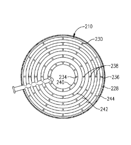
[0039] Referring now to FIG. 4, an alternate sparger 210 is depicted
having a plurality of circular fluid distribution conduits 228. The circular
fluid
distribution conduits 228 can be positioned in a concentric or substantially
concentric manner. Additionally, in various embodiments, the circular fluid
distribution conduits 228 can be spaced equiannularly or substantially
equiannularly. As can be seen in FIG. 4, the fluid distribution conduits 228
present a plurality of fluid discharge openings 230. The innermost fluid
discharge
openings 234 can be located on the innermost fluid distribution conduit 240,
the
intermediate fluid discharge openings 238 can be located on their respective
intermediate fluid distribution conduits 242, and the outermost fluid
discharge
openings 236 can be located on the outermost fluid distribution conduit 244.
The
number, spacing, and dimensions of the fluid discharge openings 230 can be the
same or substantially the same as the fluid discharge openings 30 described
above with respect to FIG. 2. Additionally, the sparger 210 can operate in the
same or substantially the same manner as the sparger 10 described above with
respect to FIGS. 1 and 2.
[0040] Referring now to FIG. 5, an alternate sparger 310 is depicted
having a plurality of square fluid distribution conduits 328. The square fluid
distribution conduits 328 can be positioned in a concentric or substantially
concentric manner. As can be seen in FIG. 5, the fluid distribution conduits
328
present a plurality of fluid discharge openings 330. In various embodiments,
the
square fluid distribution conduits 328 can be spaced such that the fluid
discharge
openings 330 are equiannularly or substantially equiannularly spaced. In one
or
16
CA 02811334 2013-03-13
WO 2012/040321 PCT/US2011/052542
more embodiments, the innermost fluid discharge openings 334 can be located
on the innermost fluid distribution conduit 340, the intermediate fluid
discharge
openings 338 can be located on their respective intermediate fluid
distribution
conduits 342, and the outermost fluid discharge openings 336 can be located on
the outermost fluid distribution conduit 344. The
number, spacing, and
dimensions of the fluid discharge openings 330 can be the same or
substantially
the same as the fluid discharge openings 30 described above with respect to
FIG. 2. Additionally, the sparger 310 can operate in the same or substantially
the
same manner as the sparger 10 described above with respect to FIGS. 1 and 2.
[0041] Referring now to FIG. 6, an alternate sparger 410 is depicted
having a plurality of octagonal fluid distribution conduits 428. The octagonal
fluid
distribution conduits 428 can be positioned in a concentric or substantially
concentric manner. As can be seen in FIG. 6, the fluid distribution conduits
428
present a plurality of fluid discharge openings 430. In various embodiments,
the
octagonal fluid distribution conduits 428 can be spaced such that the fluid
discharge openings 430 are equiannularly or substantially equiannularly
spaced.
In one or more embodiments, the innermost fluid discharge openings 434 can be
located on the innermost fluid distribution conduit 440, the intermediate
fluid
discharge openings 438 can be located on their respective intermediate fluid
distribution conduits 442, and the outermost fluid discharge openings 436 can
be
located on the outermost fluid distribution conduit 444. The number, spacing,
and dimensions of the fluid discharge openings 430 can be the same or
substantially the same as the fluid discharge openings 30 described above with
respect to FIG. 2. Additionally, the sparger 410 can operate in the same or
substantially the same manner as the sparger 10 described above with respect
to
FIGS. 1 and 2.
[0042] Referring now to FIG. 7, a sparger 510 can be employed in a
bubble column reactor 512 in a system 514 for at least partially oxidizing an
oxidizable compound (e.g., para-xylene) to form a dicarboxylic acid (e.g.,
terephthalic acid). The system 514 is depicted as comprising an initial
oxidation
reactor 516, an initial oxidation side-draw reactor 518, a secondary oxidation
reactor 520, and the bubble column reactor 512, which can be a side-draw
reactor. The sparger 510 can have the same or substantially the same
17
CA 02811334 2013-03-13
WO 2012/040321 PCT/US2011/052542
dimensions and operate in the same or substantially the same manner as
described above with reference to any of the spargers 10, 110, 210, 310, or
410
described above with reference to FIGS. 2, 3, 4, 5, and 6, respectively.
Additionally, the bubble column reactor 512 can have the same or substantially
the same dimensions and operate in the same or substantially the same manner
as the bubble column reactor 12 described above with reference to FIG. 1.
[0043] In operation, a liquid-phase feed stream comprising an oxidizable
compound (e.g., para-xylene) and a solvent (e.g., acetic acid and/or water)
can
be introduced into the initial oxidation reactor 516 for liquid-phase
oxidation. A
gas-phase oxidant (e.g., air) can also be introduced into the initial
oxidation
reactor 516 via a sparger 522. In one or more embodiments, the initial
oxidation
reactor 516 can be a bubble column reactor, so that agitation of the resulting
reaction medium in the reaction zone 524 of the initial oxidation reactor 516
is
primarily provided by bubbles of the incoming gas-phase oxidant. Oxidation of
the oxidizable compound can be a precipitation reaction producing a three-
phase
reaction medium. Following initial oxidation, the resulting off-gas can be
discharged via a line 526, and the resulting crude dicarboxylic acid slurry
(e.g., a
crude terephthalic acid ("CTA") slurry) can be withdrawn via a side-draw
conduit
528.
[0044] The slurry in the side-draw conduit 528 can be introduced into the
initial oxidation side-draw reactor 518 where it can undergo further oxidation
via
contact with additional gas-phase oxidant (e.g., air or a combination of air
and
steam). The off-gas resulting from further oxidation in the initial oxidation
side-
draw reactor 518 can be withdrawn via a line 530, while the resulting slurry
can
be withdrawn via a line 532.
[0045] The slurry from the line 532 can be introduced into the secondary
oxidation reactor 520. Additionally, additional gas-phase oxidant (e.g., air)
can
be mixed with the slurry from the line 532 prior to introduction into the
secondary
oxidation reactor 520. Alternatively, additional gas-phase oxidant (e.g., air)
can
be introduced into the secondary oxidation reactor 520 separately. Additional
solvent (e.g., acetic acid and/or water) can be introduced into the secondary
oxidation reactor 520 via a sparger 534. In one or more embodiments, the
secondary oxidation reactor 520 can be a continuous stirred tank reactor
18
CA 02811334 2013-03-13
WO 2012/040321 PCT/US2011/052542
("CSTR"), so that agitation of the resulting reaction medium in the reaction
zone
536 of the secondary oxidation reactor 520 is primarily provided by mechanical
means. In alternate embodiments, the secondary oxidation reactor 520 can be a
bubble column reactor. Following secondary oxidation, the resulting off-gas
can
be discharged via a line 538, and the resulting purified dicarboxylic acid
slurry
(e.g., a purified terephthalic acid ("PTA") slurry) can be withdrawn via a
side-draw
conduit 540.
[0046] The slurry in the side-draw conduit 540 can be introduced into the
bubble column reactor 512 where it can undergo further oxidation via contact
with
additional gas-phase oxidant (e.g., air). As noted above, the additional gas-
phase oxidant can be introduced into the reaction zone 542 of the bubble
column
reactor 512 via the sparger 510, which can have the same configuration as any
of
the above-described spargers of FIGS. 2-6. The off-gas resulting from the
additional oxidation in the bubble column reactor 512 can be withdrawn via a
line
544, while the resulting slurry (e.g., a terephthalic acid slurry) can be
withdrawn
via a line 546.
DEFINITIONS
[0047] It should be understood that the following is not intended to be an
exclusive list of defined terms. Other definitions may be provided in the
foregoing
description, such as, for example, when accompanying the use of a defined term
in context.
[0048] As used herein, the terms "a," "an," and "the" mean one or more.
[0049] As used herein, the term "and/or," when used in a list of two or
more items, means that any one of the listed items can be employed by itself
or
any combination of two or more of the listed items can be employed. For
example, if a composition is described as containing components A, B, and/or
C,
the composition can contain A alone; B alone; C alone; A and B in combination;
A
and C in combination, B and C in combination; or A, B, and C in combination.
[0050] As used herein, the terms "comprising," "comprises," and
"comprise" are open-ended transition terms used to transition from a subject
recited before the term to one or more elements recited after the term, where
the
19
CA 02811334 2013-03-13
WO 2012/040321 PCT/US2011/052542
element or elements listed after the transition term are not necessarily the
only
elements that make up the subject.
[0051] As used herein, the terms "having," "has," and "have" have the
same open-ended meaning as "comprising," "comprises," and "comprise"
provided above.
[0052] As used herein, the terms "including," "includes," and "include" have
the same open-ended meaning as "comprising," "comprises," and "comprise"
provided above.
NUMERICAL RANGES
[0053] The present description uses numerical ranges to quantify certain
parameters relating to the invention. It
should be understood that when
numerical ranges are provided, such ranges are to be construed as providing
literal support for claim limitations that only recite the lower value of the
range as
well as claim limitations that only recite the upper value of the range. For
example, a disclosed numerical range of 10 to 100 provides literal support for
a
claim reciting "greater than 10" (with no upper bounds) and a claim reciting
"less
than 100" (with no lower bounds).
[0054] The present description uses specific numerical values to quantify
certain parameters relating to the invention, where the specific numerical
values
are not expressly part of a numerical range. It should be understood that each
specific numerical value provided herein is to be construed as providing
literal
support for a broad, intermediate, and narrow range. The
broad range
associated with each specific numerical value is the numerical value plus and
minus 60 percent of the numerical value, rounded to two significant digits.
The
intermediate range associated with each specific numerical value is the
numerical
value plus and minus 30 percent of the numerical value, rounded to two
significant digits. The narrow range associated with each specific numerical
value is the numerical value plus and minus 15 percent of the numerical value,
rounded to two significant digits. For example, if the specification describes
a
specific temperature of 62 F, such a description provides literal support for
a
broad numerical range of 25 F to 99 F (62 F +/- 37 F), an intermediate
numerical range of 43 F to 81 F (62 F +/- 19 F), and a narrow numerical range
CA 02811334 2013-03-13
WO 2012/040321 PCT/US2011/052542
of 53 F to 71 F (62 F +/- 9 F). These broad, intermediate, and narrow
numerical ranges should be applied not only to the specific values, but should
also be applied to differences between these specific values. Thus, if the
specification describes a first pressure of 110 psia and a second pressure of
48
psia (a difference of 62 psi), the broad, intermediate, and narrow ranges for
the
pressure difference between these two streams would be 25 to 99 psi, 43 to 81
psi, and 53 to 71 psi, respectively.
CLAIMS NOT LIMITED TO DISCLOSED EMBODIMENTS
[0055] The preferred forms of the invention described above are to be
used as illustration only, and should not be used in a limiting sense to
interpret
the scope of the present invention. Modifications to the exemplary
embodiments,
set forth above, could be readily made by those skilled in the art without
departing from the spirit of the present invention.
[0056] The inventors hereby state their intent to rely on the Doctrine of
Equivalents to determine and assess the reasonably fair scope of the present
invention as it pertains to any apparatus not materially departing from but
outside
the literal scope of the invention as set forth in the following claims.
21