Note: Descriptions are shown in the official language in which they were submitted.
CA 02811361 2013-03-14
SGL CARBON SE 2010/050W0
1 06.03.2013
Cathode for electrolytic cells
The invention relates to a cathode for an electrolytic cell for extracting
aluminium by fused-salt electrolysis.
The Hall-Heroult process is currently used for the industrial extraction of
aluminium from its oxide. This is an electrolytic process in which aluminium
oxide (A1203) is dissolved in molten cryolite (Na3 [AlF6]) and the resulting
mixture acts as a liquid electrolyte in an electrolytic cell. In principal,
the
design of this sort of electrolytic cell used to carry out the Hall-Heroult
process
is depicted schematically in Figures 1a to 1c, wherein Figure 1a shows a
cross-section through a traditional cell, while Figure lb shows an external
side
is view of the cell. Fig. lc shows a perspective view of an electrolytic
cell.
Reference symbol 1 denotes a cathode, which may, for example, be made
from graphite, anthracite or a mixture of these. Alternatively, coke-based
graphitised cathodes may also be used. The cathode 1 is generally enclosed
in a mounting 2 made from steel and/or a fire-resistant material or similar.
The
cathode 1 may be made in one-piece or also from individual cathode blocks.
Over the entire length of the cell, a number of current supply bars 3 are
introduced into the cathode 1, although only a single current supply bar 3 can
be seen in the cross-sectional view in Figure la. It can be seen in Fig. 1c
that
two current supply bars, for example, may be provided for each cathode
block. The current supply bars are used to supply the cell with the current
required for the electrolytic process. There is a plurality of typically
prismatic
anodes 4 opposite the cathode 1, wherein two anodes 4 are schematically
depicted in Figure 1a. Fig. 1c shows a detailed configuration of anodes in an
electrolytic cell. During the performance of the process, the aluminium oxide
dissolved in cryolite is split into aluminium and oxygen ions by applying a
voltage between the cathode 1 and the anodes 4, in which case the
CA 02811361 2013-03-14
SGL CARBON SE 2010/050
WO
2
06.03.2013
aluminium ions move to the molten aluminium ¨ actually the cathode from an
electrochemical point of view ¨ where they accept electrons. Due to the
greater density, aluminium 5 gathers in the liquid phase beneath the molten
mixture 6 of aluminium oxide and cryolite. The oxygen ions are reduced to
oxygen at the anode, said oxygen reacting with the carbon of the anodes.
Reference symbols 7 and 8 are the schematic representations of the negative
and positive poles, respectively, of a voltage source for supplying the
voltage
required for the electrolytic process, the value of which lies between around
3.5 and 5 V, for example.
As can be seen in the side view in Figure lb, the mounting 2 and therefore the
entire electrolytic cell has an elongated form, in which a plurality of
current-
carrying bars 3 are conducted vertically through the side walls of the
mounting
2. The longitudinal expansion of cells currently in use is typically between
around 8 and 15 m, while the width expansion is about 3 to 4 m. A cathode,
as is shown here in Figure 1a, is disclosed in EP 1845174, for example.
In traditional cathode blocks, all component parts are essentially made from
only one material. However, this does not allow for the fact that different
requirements are made of different parts of a cathode in a fused-salt
electrolytic process. Hence, there is a material loss due to cathode material
wear within the range of the electrolytic bath or in that part of the cathode
that
comes into contact with the molten aluminium in the process described,
particularly due to chemical and mechanical processes involved in the
electrolytic process like for example flow movements. For this reason, the
cathode has to be renewed from time to time, i.e. in this case the entire
lining
of the electrolytic cell has to be replaced. In general, this sort of change
will
take place every 1500 to 3000 days. In addition, compromises must be made
in relation to optimum design when it comes to individual components, since
the requirements made of individual components are irreconcilable in some
cases. Moreover, because of the frequent replacement of all materials, such
as cathode blocks, ramming mass, side mounting and insulating material top-
'
CA 02811361 2013-03-14
SGL CARBON SE 2010/050
WO
3 06.03.2013
quality materials have to be dispensed with, 'so that aluminium production
costs do not become excessively high.
One problem addressed by the invention is therefore to specify a cathode for
an electrolytic cell used to extract aluminium, which allows the
aforementioned
disadvantages of the state of the art to be overcome, a material cost saving
to
be made in particular and, at the same time, the cathode to be optimised in
terms of its functionality.
to This problem is solved according to the invention by a cathode with the
features contained in claim 1. Preferred embodiments are specified in the
dependent claims.
A cathode for an electrolytic cell used to extract aluminium from its oxide in
an
is electrolytic bath in accordance with the embodiments of the invention
exhibits
the following: a) an upper part facing the electrolytic bath and b) a lower
part
provided with current supply connections. According to the invention, the
upper part and the lower part are detachably connected to one another at
least in sections by an intermediate layer. The upper part in this case is a
20 base tray, which is in direct contact with the electrolytic bath during
use.
The term "cathode" denotes the upper part connected to the lower part in the
context of the present invention. Within the meaning of the invention, the
term
cathode is interpreted quite generally. It may be, for example (although not
25 exclusively), a so-called cathode bottom, which is made from a plurality
of
cathode blocks, so that the core aspects according to the invention ¨ namely,
the structure described above comprising an upper part connected to a lower
part ¨ are realised as a whole by this cathode bottom. However, the term
cathode is also intended to refer to the partial structures forming such a
30 cathode bottom, as in cathode blocks. All features that may contribute
to the
invention in relation to a "cathode" do so in the same way in relation to a
"cathode block", without this having to be expressly explained below.
CA 02811361 2013-03-14
SGL CARBON SE 2010/050 WO
4 06.03.2013
Due to the cathode's two-part design,. it is possible to optimise the
different
functional areas during manufacture. Hence, the upper part is used to hold the
liquid electrolyte and the end product, namely the molten aluminium, during
the process.
The upper section, which can also be referred to as the "consumption part" of
the cathode, should be designed to be as resistant as possible to wear, such
as that resulting from mechanical, thermal and/or chemical loads. Due to the
fact that the upper section has to be occasionally replaced in any event, due
io to the consumption of cathode material during the electrolytic reaction,
the
cost of the material used in the upper section should be kept low. The lower
part of the cathode, on the other hand, must be designed for optimum current
supply and distribution. Due to this two-part construction, which is a feature
of
the present invention, both parts (upper part and lower part) can now be
is produced separately from one another and then combined by means of the
intermediate layer. In this way, each part can be optimised in terms of its
function, without this having a detrimental effect on the function of the
other
part in each case. So, for example, the lower part may be made from higher-
grade, expensive, yet at the same time barely wear-resistant material,
20 because it is unaffected by wear or replacement of the upper part due to
wear.
A substantial material cost saving is made as a result of this, because an
entire cathode is not affected by the replacement in each case or all cathode
blocks do not have to be replaced.
25 A further advantage of the invention is that the lower part can be
protected
from the chemical effects of the electrolytic bath by the intermediate layer.
The
intermediate layer therefore not only makes a design possible with a separate
upper and lower part, but it also helps that the advantage that the lower part
can be made from high-grade material, is not destroyed again by corrosive
30 liquids or gases penetrating as far as to the lower part, such as liquid
aluminium or electrolyte components.
The intermediate layer, which connects the upper part to the lower part, may
CA 02811361 2013-03-14
SGL CARBON SE 2010/050 WO
06.03.2013
be produced from graphite foil, for example, Particularly being a graphite
foil.
A graphite foil is particularly well-suited to avoiding or at least largely
preventing the penetration of the lower part by liquid and/or gaseous bath
components, like for example liquid aluminium or electrolyte components,
5 while leaving the actual function of the cathode as a whole largely
unchanged.
As an intermediate layer, graphite foil has similar electrical properties as
the
cathode components, particularly as the lower part. Graphite foil, which is
produced by the at least partial compression of expanded graphite, is
particularly well-suited as a barrier layer acting against chemical influences
from the electrolytic bath, due to its anisotropy in the foil surface and
therefore
low permeability perpendicular to the foil. Graphite foil furthermore has the
effect of balancing differences in surface structure between the upper part
and
the lower part, as well as thermal expansion and contraction movements,
particularly in the upper part. Graphite foil has a low electrical contact
resistance to other carbon materials and a very good electrical conductivity.
Although the specific electrical resistance perpendicular to the graphite foil
is
higher than in the foil surface, very low absolute electrical resistance can
be
achieved due to the very low thickness of graphite foil.
In the event of that the cathode is produced from individual cathode blocks,
the intermediate layer is preferably not provided to fit the size of the
cathode
blocks, but advantageously covers a larger area than the lower part of the
cathode blocks in each case. The intermediate layer may advantageously
display an area that corresponds to the size of the cathode as a whole.
The intermediate layer may be designed with a very low thickness. For
example, the layer may simply be a single sheet of graphite foil. A range of 1
mm to 5 mm range, for example, has proved to be a suitable foil thickness.
This thickness is sufficient to fulfil the functions described, yet it is thin
enough
for the foil properties not to adversely affect the functionality of the
cathode as
a whole to any significant extent.
It may also be advantageous to use a plurality of graphite foils layered on
top
CA 02811361 2013-03-14
SGL CARBON SE 2010/050 WO
6 06.03.2013
of one another or graphite foils with greater thicknesses. The intermediate
layer may be adjusted as desired or as necessary in relation to its specific
electrical conductivity and/or its electrical contact resistance. A coating of
the
intermediate layer may also be provided in this respect, which reduces contact
resistance. The specific electrical conductivity of the graphite foil in
direction of
the thickness may also be selectively increased by known measures.
According to the state of the art a suitable current supply within the cathode
is
used to keep the material loss at the cathode surface inside the cathode tank
Jo as uniform as possible. Since optimisation of the current supply in
embodiments of the invention can be selectively undertaken in the lower part,
it is possible for the upper part to be correspondingly simple in terms of its
design and therefore its manufacture.
In a cathode according to the invention, the upper part may be formed in one
piece together with a side wall of the electrolytic cell. This means that the
base wall and the side walls are formed from a single piece. Problems
associated with sealing and jointing between the base wall and side walls are
thereby avoided.
Since the lower part of the cathode does not come into contact with the liquid
electrolyte or the aluminium melt during use in a fused-salt electrolytic
process, resistance to mechanical or chemical wear is not a criterion in this
part. Consequently, this part only has low maintenance requirements, if any at
all, and does not have to be replaced at regular intervals, as is the case
with
the upper part. For this reason, higher-grade materials can be used for the
lower part. An example of such a material is highly-conductive graphite, as a
crucial disadvantage of graphite, namely its low mechanical wear resistance,
does not apply to this application.
According to a preferred embodiment, the lower part may be produced using,
for example, needle coke as the raw material. As is generally known, needle
coke is the highest-grade petroleum or pitch coke, its name being derived
CA 02811361 2013-03-14
SGL CARBON SE 2010/050
WO
7 06.03.2013
from its needle-like structure. Needle coke is characterised by, among other
things, its lower thermal coefficient of expansion and its low specific
electrical
resistance after graphitisation, in longitudinal direction of the needle-like
structure. This is advantageous particularly in the lower part of the cathode,
where high-density currents flow. By means of a suitable design, alignment of
the needle-shaped coke particles can be achieved in a perpendicular position.
The reduction in specific electrical resistance causes a smaller voltage drop
at
the cathode and thereby helps greater energy efficiency to be achieved during
fused-salt electrolysis. Because energy costs constitute a major part of the
total process costs, significant savings can be made in this way.
The upper part of the cathode may be made from any known materials
suitable for use as a cathode. Raw materials particularly worth mentioning in
this context are calcined anthracite, coke or graphite. The raw material is
is ground and sorted according to particle size. A defined mixture of
fractions in
the grain size is combined with pitch and then used to form the upper part.
Subsequent to this, one or more production steps are carried out at an
increased temperature, a distinction being made between a graphitised, a
graphitic and an amorphous cathode material based on the heat treatment
temperature and raw materials.
The cathode may advantageously have a vertical current supply. This means
that current is introduced into the lower part of the cathode vertically from
below. This means that an uneven current distribution in the cathode, as is
the
case with a traditional horizontal current supply, can be advantageously
avoided.
In accordance with an embodiment of the cathode in the invention, the lower
part may be provided with vertical pins as current supplies. These pins may
be in the form of grub screws, with the lower part exhibiting threaded holes
as
connections to hold the grub screws. Pins with an external thread may be
screwed into the threaded holes in the lower part of the cathode vertically or
approximately vertically. In this way, the current can be introduced into the
CA 02811361 2013-03-14
SGL CARBON SE 2010/050 WO
8 06.03.2013
cathode roughly vertically during fused-salt electrolysis. The current supply
can be kept very uniform during this by adapting the number and diameter of
the pins to the cathode geometry.
The geometry of the pins may advantageously match the geometry of
threaded nipples for graphite electrodes used in electric steel production.
This
geometry has proved to be particularly good in relation to the current
distribution, mechanical strength and screwability. The relatively large pin
cross-section effects a high electrical current flow, the length effects a
sufficiently large interval between the cathode and therefore the electrolytic
cell and the current supply bars, so that a high level of cooling is possible.
In accordance with a preferred embodiment, the pins are made from graphite.
This enables a high thermal stability of the pins and low electrical
resistance
is to be achieved, which leads to a reduction in specific energy costs
associated
with the performance of the fused-salt electrolysis.
In terms of a uniform current supply, it has also proved to be beneficial if
the
lower part of the cathode is designed in the form of a trapezoidal body
tapering downwards. In this way, the current introduced vertically or
approximately vertically is distributed uniformly and evenly in the upper part
of
the cathode. In the case that the cathode is made from individual cathode
blocks, at least some of the cathode blocks of the cathode preferably have
this sort of trapezoidal, downward-tapering body, in which case these
advantageously extend parallel to one another. The trapezoidal bodies may,
for example, run longitudinally to the cathode or perpendicular to it.
It should be noted that in the context of the invention the expression
"approximately vertical" is used to cover all directions that include an angle
of
less than roughly 20 to the perpendicular. However, "vertical" in the
broadest
sense should include all vertical supplies that are not horizontally in the
traditional manner.
CA 02811361 2013-03-14
SGL CARBON SE 2010/050 WO
9 06.03.2013
The invention will now be described in greater detail with reference to the
attached drawing using a non-restrictive exemplary embodiment. In the
drawing:
Fig. la shows a schematic cross section of an electrolytic cell for the
extraction of aluminium oxide according to the state of the art;
Fig. lb shows the electrolytic cell from Fig. lain an external
longitudinal
view;
Fig. lc shows a perspective view partially in section of an
electrolytic
cell for the extraction of aluminium from aluminium oxide
according to the state of the art;
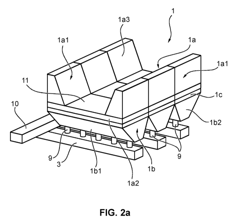
Fig. 2a shows a perspective view of a cathode unit according to an
embodiment of the invention; and
Fig. 2b shows a representation of the cathode unit in Fig. 2a from a
90
rotated perspective.
The same reference symbols are used in the figures to refer to the same or
corresponding elements in the different representations.
With reference to Figures 2a and 2b, an electrolytic cell with an embodiment
of a cathode 1 according to the invention is shown from different perspectives
in each case. The cathode 1 shown is suitable for use in the extraction of
aluminium from aluminium oxide using the Hall-Heroult process. In this case
the electrolytic cell is provided with two side walls lal, which, along with a
base wall 1a2, hold the electrolyte bath. In the case shown, the side walls
lal
extend along the longitudinal side of the cathode I. The side wall lal is made
from individual side wall blocks 1a3. The base wall 1a2 represents an upper
or first part 1 a of the cathode 1. The cathode 1 is made from individual
cathode blocks 11 in this embodiment.
CA 02811361 2013-03-14
SGL CARBON SE 2010/050W0
06.03.2013
In the exemplary embodiment shown a lower part lb of the cathode 1
comprises a number of connections lbl, which are formed from trapezoidal
bodies 1b2 in a lower section, which taper downwards in a V-shape. The
5 connections lbl may be in the form of internal threads, for example, (not
shown in the figures), so that they can each hold a pin 9 with a corresponding
external thread for the current supply to the cathode 1. Several of the pins 9
are connected at their sides lying opposite the connections lbl to current
supply bars 3, which lead to busbars 10, in order to connect cathode 1 to the
10 corresponding pole of a voltage source.
The upper part la and the lower part lb are connected to one another by an
intermediate layer lc, which may be a graphite foil, for example. This foil
enables the upper part of the cathode to be removed without damaging the
lower part. At the same time, the graphite foil guarantees that no liquid
aluminium or electrolyte penetrates as far as the lower part and, to this
extent,
acts as a barrier layer. Despite having poorer specific electrical
conductivity
perpendicular to the foil plane compared with the conductivity within the foil
plane, on account of its very low thickness of a few millimetres, for example,
the graphite foil has a very low absolute electrical resistance and effects a
very good electrical contact between the upper part and the lower part, so
that
the cathode's functionality is not affected. Moreover, the intermediate layer
balances an expansion of the two parts la, lb, on account of thermal
fluctuations, for example.
Since the upper part la and the lower part lb are formed separately from one
another, the two parts may be made from different materials and exhibit
different properties in relation to thermal expansion and electrical
resistance.
This means that each part can be specially optimised in functional terms. In
particular, the upper part la must be designed such that it is able to
withstand
wear, due for example to mechanical abrasion and also uneven
electrochemical decomposition, as effectively as possible.
CA 02811361 2013-03-14
SGL CARBON SE 2010/050 WO
11 06.03.2013
By contrast, the lower part lb should be designed for the most uniform current
supply possible and the highest possible energy efficiency. To achieve this,
it
can be optimised in terms of the materials used, since the relatively fast-
wearing upper part 1 a, which must be replaced more frequently, is produced
separately from the lower part lb. This means that expensive materials, such
as needle coke, for example, can also be chosen, in order to optimise the
long-lasting lower part lb in relation to the desired uniform current
distribution.
Copper and aluminium have proved to be particularly suitable as materials for
the current supply bars 3, due to their low specific electrical resistances.
Since
the current supply bars are spaced away from the cathode 1 by pins 9, they
are substantially cooled and it is therefore not necessary for them to be made
from high-temperature-resistant steel. Due to the lower specific electrical
resistance of the aforementioned metals for the current supply bars 3, less
energy is converted into waste heat and the energy efficiency during fused
salt electrolysis can be markedly improved. The tapering ld of the trapezoidal
bodies shown serves to increase the distance between the upper part 1 a of
the cathode 1 and the current-carrying current supply bars 3 and therefore
supports the cooling of the current supply bars 3.
In relation to cathode materials, any materials known to the person skilled in
the art and suitable for the electrolysis of aluminium from its oxide may be
used. Suitable materials are specified in DE 10261745, for example, the
content of which, in this respect, is to be incorporated herein by reference.
The pins 9, in particular, may be made from the same materials as the
cathode 1. Graphite has proved to be particularly favourable in this respect,
due to its temperature resistance and due to its low specific electrical
resistance.
CA 02811361 2013-03-14
SGL CARBON SE 2010/050 WO
12 06.03.2013
Reference list
1 Cathode
1 a Upper part
la 1 Side wall
la2 Base wall
1a3 Side wall block
lb Lower part
1 bl Connection
1b2 Trapezoidal body
1 c Intermediate layer
2 Mounting
3 Current supply bars, current bar
4 Anode
5 Aluminium
6 Electrolytic bath mixture (aluminium oxide, cryolite)
7 Negative pole, voltage source
8 Positive pole, voltage source
9 Pin
10 Busbar
11 Cathode block