Note: Descriptions are shown in the official language in which they were submitted.
CA 02811512 2013-03-15
WO 2012/044446 PCT/US2011/050652
1
LOCKING MEANS FOR A CAP
FIELD OF INVENTION
The present invention relates to a locking means for a cap designed to be
particularly
resistant to impact forces to provide for a leak-tight fitting whilst allowing
simple and quick
release. A preferred field of use is that of caps for large containers for
domestic or household
use, containing detergents or other cleaning preparations, fabric conditioners
and the like.
However, it is understood that said cap may equally be suitable in other
fields of use such as
containers for manual and automatic dishwashing liquids, hair-care products
and oral care
applications such as mouth washes.
BACKGROUND OF THE INVENTION
It may be desirable to provide a locking means for a cap which allows
effective tight
locking against accidental knock-over whilst still allowing quick and
effortless opening and
closing of said cap.
Various solutions exist for container caps suitable for use with containers
holding fluid
base substances such as, shower gels, hair shampoos, suncreams, sun lotions,
body oils and the
like. The purpose of these caps is, on the one hand, to form a leakproof seal
so that the substance
contained within does not escape and so that outside air does not constantly
pervade the
container. On the other hand, such cap should be easy to open and close.
Caps of this kind usually have an essentially tubular-shaped cap body with a
female
thread provided in its inner wall for screwing onto, for example, an
accordingly configured
(male) thread at the upper end of a container neck. By means of a sealing
arrangement, a
leakproof connection is created between the cap and the container.
An example of such caps is U56409034B. U56409034B relates to a hinged cap body
designed for fitting with a leakproof seal on a container opening, a hinged
lid joined to the cap
body for closing an outlet aperture formed on the cap body, and a locking
arrangement formed
on the cap body and the hinged lid. Sealing is achieved via a protrusion
extending from said
hinged lid which at least partly lodges in the outlet aperture when the lid is
closed. Ease of
opening and closing is achieved via a combination of; an elastically
deformable material, which
creates a biasing force between the cap body and the hinged lid in order to
bring the hinged lid
into an open position; and a locking projection which, in closed position,
clutches rearwards to a
biased, manually operable locking element which is disposed on the cap body.
The locking
CA 02811512 2013-03-15
WO 2012/044446 PCT/US2011/050652
2
arrangement is especially simple to use in that only a light pressure must be
manually applied to
disengage the locking element from the locking projection and allow the
elastically deformable
material to flip the hinged lid open.
Such device introduces a number of disadvantages. One disadvantage is that the
hinged
lid may easily flip open if the container is accidentally knocked over by the
user and cause
spillage of the content. Another disadvantage is that the only sealing means
for preventing the
content to exit the outlet aperture is the protrusion on the hinged lid which
may leak when
subjected to high pressures caused by, for example, high impact forces during
transportation.
Further disadvantages may be: alignment problems between the protrusion and
the outlet
aperture in case of distortion of the hinges and/or its suitability only for
small outlets.
Other caps exist providing various locking mechanisms, particularly for child-
proof
containers of medications. Caps of this kind use mechanisms such as the "push-
and-turn" system
or other mechanisms such as those described in W02006/102601A1 and
U57404495B2, which
require the combination of a radial force and an upward force applied onto a
portion of said
locking mechanism to open said cap. Although these mechanisms may be useful in
preventing a
child from opening the caps, they render singlehanded operation difficult,
which may be
important for certain users, such as for elderly.
Further caps exist providing a moisture resistant closure such as those
described in
EP2218654A1. EP2218654A1 relates to a cap comprising a base portion with an
outer periphery
adapted to extend over at least a portion of a container, a skirt depending
downwardly from the
base portion and a lip seal member depending downwardly from the base portion.
The container
has an opening bounded by a lip extending upwards from the container. The lip
seal member is
adapted to abut an interior side of the lip, when the cap is in closed
position.
Such devices, although suitable for preventing moisture entering or exiting
the container,
do not provide a strong enough locking force to prevent the lid from opening
upon impact.
Furthermore, such devices rely solely on a single sealing surface thus more
likely to leak during,
for example; handling of the container by the user wherein the container is
subjected to a given,
albeit small, holding pressure; or accidental knock-over.
Thus, it is an object of the present invention to overcome the abovementioned
problems
whilst providing a simple, cost-effective, efficient in use and compact
solution.
In one aspect of the present invention, it is an object to provide a cap that
tightly locks
and seals a container to prevent undesired leakage throughout all stages of
the supply chain,
while providing quick and effortless opening and closing of said cap.
CA 02811512 2013-03-15
WO 2012/044446 PCT/US2011/050652
3
In another aspect of the present invention, it is an object to provide a cap
resistant to
deflections, particularly deflections arising from tightening of said cap onto
the neck of a
container, to ensure even more effective leak-tight sealing.
In another aspect of the present invention, it is an object to provide a
locking means for a
cap which allows tight locking against impact while being quick and easy to
open, particularly
single-handedly.
Other objects, features and advantages of the invention will be better
understood with
reference to the attached drawings and the specification hereinafter.
SUMMARY OF THE INVENTION
In one aspect, the present invention relates to a locking means for a cap
capable of
connecting to a container, said locking means comprising a panel connected to
a lid of said cap
on at least a portion of the perimeter thereof. At least one protrusion
extending from a portion of
said panel towards the inside of said lid for coupling with a slot provided in
a portion of a cap
body of said cap and further, an elastically deformable material connecting
said panel to said lid,
wherein at least a portion of said protrusion (26) extends at an angle c and
wherein at least a
portion of said slot (27) is slanted at an angle b so that coupling with said
protrusion (26) is
achieved when said lid (3) is pressed onto said cap body (2), and wherein the
angle c of said
protrusion (26) is between 1 and 2 degrees and the angle b of said slot (27)
is between 0 and 2
degrees, taken from a plane perpendicular to the longitudinal axis (YY).
In another aspect, the present invention relates to a cap capable of being
connected to a
container, comprising a locking means.
BRIEF DESCRIPTION OF THE DRAWINGS
Fig. 1A is a front view of the cap according to one embodiment of the present
invention.
Fig. 1B is a side view of the cap according to one embodiment of the present
invention.
Fig. 2 is a cross-section taken along the line A-A of Fig. 1A of the cap
according to one
embodiment of the present invention.
Fig. 3 is the cross-section of Fig. 2 with the lid in its open position.
Fig. 4 is a blow-up of portion X of Fig. 2 of the cap according to one
embodiment of the
present invention.
CA 02811512 2013-03-15
WO 2012/044446 PCT/US2011/050652
4
Fig. 5 is a top view of the cap according to one embodiment of the present
invention in its
open position.
Fig. 6 is a side cross-section view of the cap according to one embodiment of
the present
invention with the lid in its semi-closed state.
Fig. 7 is a top view of the cap according to one embodiment of the present
invention in its
closed position.
Fig. 8A to C are side cross-section views of the cap according to one
embodiment of the
present invention illustrating the opening of said cap.
Fig. 9 is a graph illustrating the drop test for caps according to embodiments
of the
present invention connected to containers of 3 liters. These results indicate
that caps of the
present invention remain closed and sealed at an average drop height of 139cm.
DETAILED DESCRIPTION OF THE INVENTION
By the terms "a" and "an" when describing a particular element, we herein mean
"at least
one" of that particular element.
The term "lock or locking" as used herein means that the cap is tightly
secured in its
closed position. By the term "tightly secured" as used hereinbefore it is
meant that said cap
withstands a force of at least 30N, preferably at least SON , and more
preferably at least 70N.
The term "large container" as used herein means containers for holding at
least 1.5 liters,
preferably at least 2 liters of a liquid, more preferably from 2 liters to 5
liters, most preferably
from 2 liters to 3 liters.
The term "pressure in the radial direction" or "radial pressure" as used
herein means a
pressure in a direction substantially perpendicular to the longitudinal axis
(YY).
The invention is directed to a locking means particularly suitable for a cap
(1), preferably
suitable for large containers, and particularly holding a liquid. The
containers may be of any
shape and size and made of any material; resilient, flexible, rigid or
otherwise. Suitable materials
include but are not limited to plastic and glass.
The following sections will illustrate in detail the essential features and
preferred
embodiments of the present invention.
CA 02811512 2013-03-15
WO 2012/044446 PCT/US2011/050652
Cap
The cap (1) may comprise a cap body (2) capable of being connected to a
container and a
lid (3) for coupling with said cap body (2). Said cap (1) may further
comprises a disposable
sealing means (4) sealing an outlet opening (5) located on said cap body (2),
and a locking means
5 disposed on said cap body (2) and said lid (3) to lock said lid (3) onto
said cap body (2).
At least a portion of the cap (1) may be formed of a plastic material, by
injection molding
or other suitable molding techniques. For example, the cap (1) may be molded
of polypropylene.
Preferably the cap (1) will have a Tensile modulus of at least 1500 MPa,
preferably between
1600 and 1700 MPa. In one embodiment, the said at least one portion of the cap
(1) can be
formed as a single unit. Alternatively, said at least one portion of the cap
(1) may be molded
independently and then subsequently assembled.
Cap Body
The cap (1) may comprise a cap body (2) having a longitudinal axis (YY)
extending
parallel to the centerline thereof. Said cap body (2) may comprise an outlet
opening (5) therein,
preferably said cap body (2) comprises a spout (6) with said outlet opening
(5) being located
therein.
Referring to Fig. 2 and Fig. 3, said cap body (2) may comprise an outer wall
(7) defining
the shape of said cap body (2). Preferably, the average thickness of said
outer wall (7) is
typically between 2.0 mm and 2.5 mm. Said outer wall (7) may be defined by an
outer surface
(8) and an inner surface (9). Said cap body (2) may further comprise a first
surface of contact
(10) located on said outer surface (8) and may subtend from a portion
substantially proximal to
the apex of said outer surface (8) of said outer wall (7). Said first surface
of contact (10) is
preferably non-linear such that when at least a portion of the locking means,
preferably a portion
of a panel thereof, abuts said first surface of contact (10), a sliding motion
is encouraged.
Preferably said first surface of contact is curved with the greatest gradient
being located
proximal to the apex of said outer wall (7). If the cap comprises a hingedly
connected lid, said
first surface of contact is preferably located opposite the hinge (11).
In one embodiment said spout (6) may extend from a first portion, defining a
top (12),
vertically displaced from said outer wall (7), to a second portion, defining a
base (13). Said base
(13) may comprise said opening therein 0. Preferably, said base (13) may be
capable of entering
CA 02811512 2013-03-15
WO 2012/044446 PCT/US2011/050652
6
in at least a portion of the container to which said cap (1) is connected to.
Said spout (6) may be
constructed to have a substantially flat top (12). Alternatively, said top
(12) may be slanted at an
angle and present a curvature on its uppermost surface. It may be particularly
desirable for the
distance between the uppermost portion of the top (12) of the spout (6) and
the apex of said outer
wall (7) to be at least 6 mm preferably at least 7mm, more preferably between
7 and 10 mm. It is
understood that said distance between the uppermost portion of the top (12) of
the spout and the
apex of said outer wall (7), and thus the total height of the spout (6), may
also be determined by
the height of said lid (3). This embodiment is particularly advantageous for
allowing pouring of a
liquid content to be achieved in a predetermined direction without dripping
onto the outer wall
(7) and/or container. Introducing a spout (6) having a sufficient height such
that the distance
between the uppermost portion of said top (12) and the apex of said outer wall
(7) satisfies the
abovementioned range significantly affects the total height of the cap (1).
Indeed, there may be
instances where it is desirable to keep the total height of said cap (1) as
low as possible, for
example, due to shelf space restrictions whereby in order to have the largest
possible container,
the cap (1) height needs to be constrained. In these particular scenarios it
may become
particularly important to further minimize any upward deflections of the cap
body (2) that may
arise during tightening of the cap (1) onto the container to prevent the spout
(6) from pushing
onto a portion of the cap lid (3).
The cap body (2) may further comprise a female thread (14) extending from said
inner
surface (9) for coupling with a container neck threaded accordingly, to secure
said cap body (2)
onto said container.
Referring to Fig. 4, said cap body (2) may comprise a bridge-type portion (15)
formed by
a portion of the outer wall (7), preferably said portion of the outer wall (7)
is the uppermost
portion thereof. In this embodiment, said bridge-type portion (15) comprises a
flat notch (16)
capable of contacting the uppermost surface of a container neck when said cap
body (2) is fully
screwed onto said container neck. Preferably, said flat notch (16) is oriented
so that the flat
surface (17) thereof makes contact with said uppermost surface of the
container when said cap
body (2) is fully screwed on. In this embodiment, the distance "a" between the
apex of said
bridge-type portion (15) and said flat surface (17) is between 2mm and 3mm,
preferably between
2.2mm and 2.5mm. This specific notch configuration and range of thickness has
been found to
be particularly beneficial to reduce the stress concentrations generated upon
tightening of the cap
CA 02811512 2013-03-15
WO 2012/044446 PCT/US2011/050652
7
body (2) onto the container neck and to contribute in stiffening the bridge-
type portion region
against deflection at high torque.
In a preferred embodiment, said cap body (2) may comprise a plug seal (18)
proximal
said flat notch (16) extending substantially parallel to the longitudinal axis
(YY) of said cap body
(2). The plug seal (18) may be capable of contacting at least a portion of the
inner surface of a
container neck, when said cap body (2) is coupled to said container.
In a preferred embodiment, said flat notch (16) and plug seal (18) may provide
a sealing
means when the cap body (2) is screwed tightly onto a container neck by
blocking any passages
which may be formed in the connecting portion between said cap body (2) and
said container
neck and preventing any content from escaping through said passages.
In a further embodiment, said bridge-type portion (15) may be generally
curvilinear,
preferably said bridge-type portion (15) may present a curvature having a
radius of between
4.5mm and 5.5mm, preferably 5.0mm. This configuration has been found to reduce
the stress
concentrations to which the bridge-type portion portion is subjected to when
said cap body (2) is
tightly screwed onto a container neck.
Such stiffening, resistance to deflection and shape may become particularly
important
when tightening or over-tightening of the cap body (2) occurs. Strong
tightening of the cap body
(2) onto a container neck may be required in order to maximize the sealing
capabilities of said
cap body (2) and to prevent accidental unscrewing from said container neck. It
may also be
desirable to tighten the cap body (2) to such an extent to prevent the user to
easily unscrew it,
particularly when the cap comprises a separate lid that the user should open
instead. In these
scenarios it is desirable to screw said cap body (2) with a torque of up to
600Ncm, preferably
from 240Ncm to 600Ncm. A problem which is likely to arise at such high torque
values is
deflection of the regions subjected to the greatest force. Such deflection may
cause other
components such as the spout (6) do deflect upwardly and push onto the lid
making it easier for
the cap to open and leak. It is therefore particularly desirable for the cap
body (2) of the present
invention to be capable of being connected to a container neck with a torque
of up to 400Ncm,
preferably up to 500Ncm, more preferably up to 600Ncm, most preferably from
240Ncm to
600Ncm, without experiencing a deformation of more than 0.3mm. The
aforementioned
embodiments have been found particularly effective in withstanding a torque of
up to 400Ncm,
CA 02811512 2013-03-15
WO 2012/044446 PCT/US2011/050652
8
preferably 100Ncm to 400Ncm, more preferably 100Ncm to 500Ncm, most preferably
240Ncm
to 600Ncm, and wherein the deflection is less than 0.3mm.
In an alternative embodiment (not shown) at least a portion of the bridge-type
portion
(15) may be coated with a material capable of elastically deforming upon the
application of a
force. Preferably said material is selected from polyolefines. Alternatively
an 0-ring may be
introduced. The coating may be of a different material than that of the cap
body (2), preferably
said coating is of a material that experiences a greater elastic deformation
compared to the
material of said cap body (2). In this embodiment the portion of the bridge-
type portion (15)
being coated provides for a stiff structure while the material in the coating
purposively deforms
to provide a leak-tight seal even at lower torques.
In a preferred embodiment the cap body (2) may further comprise a flange (19)
extending
substantially parallel and proximal to the spout (6). Said flange (19) may be
located substantially
parallel and in between a portion of the inner surface (9) of the outer wall
(7) and a surface of
said spout (6). In this embodiment a gap is formed between said flange and
said portion of the
inner surface (9) to accommodate the insertion of a ridge (20) extending from
a surface of the lid
(3) when said lid (3) is closed.
Referring to Fig. 5, the spout may be of any shape such that the liquid
content inside a
container can be easily poured. Preferably, said spout (6) has a horse-shoe-
type perimeter at the
top to ease pouring in a predetermined direction. If the cap (1) has a lid (3)
hingedly connected to
said cap body (2), said predetermined direction is oriented such that it
points way and opposite
the hinge (11). In an even more preferred embodiment said spout (6) comprises
a product flow
cut off lip (21) located proximal to the uppermost portion of the top (12) of
said spout (6). Said
product flow cut off lip (21) has the advantage of reducing dripping onto
portions of the cap
body(2) which may in turn affect the smooth opening and closing of the cap
(1).
Lid
The cap (1) may comprise a lid (3). Said lid may comprise a first lid surface
(22) defining
the outside shape and perimeter of said lid (3).
In a preferred embodiment said lid (3) may comprise a ridge (20) extending
within and
substantially parallel to said first lid surface (22) which is capable of
inserting in between a
CA 02811512 2013-03-15
WO 2012/044446 PCT/US2011/050652
9
flange (19) and a portion of the inner surface (9) of the outer wall (7) of
the cap body (2) when
said lid (3) is closed. This configuration is particularly advantageous in
providing an additional
sealing means when said lid (3) is locked onto said cap body (2).
In a preferred embodiment said lid (3) may be hingedly connected to the cap
body (2)
with one or more hinges (11). This configuration aids single-handed opening of
the cap (1) since,
once unlocked, the lid (3) simply pivots to the open position with pressure
applied by the user.
Alternatively the hinge may comprise a spring element that forces the lid (3)
to open upon
unlocking. Suitable spring elements may include any elastic object that stores
mechanical
energy, such as springs, including but not limited to cantilever springs, coil
springs, helical
springs, torsion springs, and/or elastically deformable materials such as
thermoplastic elastomers
(TPE). Preferably the one or more hinges (11) are one part with said lid (3)
and said cap body (2)
and are made of the same material. It is however understood that other types
of hinges may
equally be suitable such as flush type hinges, butterfly hinges, butt hinges
and the like which are
welded or similarly joined to said lid (3) and said cap body (2).
Referring to Fig. 6 and Fig. 7, the lid (3) may comprise a top surface (23)
defining the
uppermost outer surface of said lid (3). Said top surface (23) may comprise an
inner top face
facing the inside of the container when said lid (3) is closed onto the cap
body (2). In a preferred
embodiment said top surface (23) comprises an interconnected groove (24). By
"interconnected"
it is herein meant that the groove (24) forms a closed shape, thus the groove
(24) does not have a
beginning nor an end. Preferably, said shape is circular. It is however,
understood that other
shapes may equally be suitable such as oval, square, rectangular, triangular
and so on. In this
embodiment, such groove (24) allows for attachment of a doser onto the top of
said lid (3).
The lid (3) may be made of the same material as the cap body. Preferably said
material is
selected from polyolefines and more specifically polypropylene.
Disposable sealing means
The cap (1) may further comprises a disposable sealing means (4) sealing the
outlet
opening (5) on the cap body (2).
In a preferred embodiment said disposable sealing means (4) may be welded on
at least a
portion of the base (13) of the spout (6) to form a resistant sealing means
against high pressure
CA 02811512 2013-03-15
WO 2012/044446 PCT/US2011/050652
build-up particularly due to large impact forces. Preferably the material of
said disposable
sealing means (4) is selected from polyethylene therephthalate (PET),
polyurethane, aluminum
foil, polypropylene and mixtures thereof. Suitable films of this type
typically comprise PET
12 m/Adhesive 5 um /ink (optional)/soft aluminium foil 38 um /coextruded
welding layer 116
5 um.
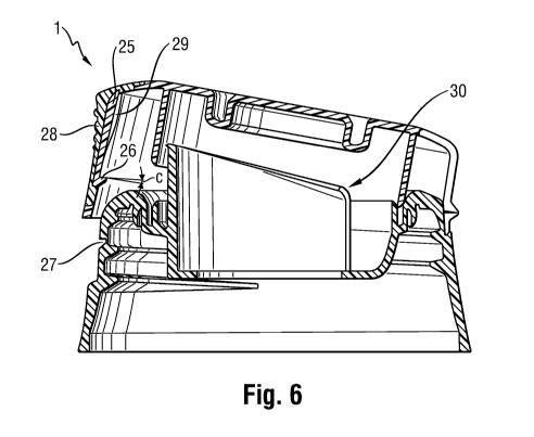
In another embodiment the disposable sealing means (4) may comprise a pull tab
(30) for
easy removal of said disposable sealing means (4). A pull tab (30) is
particularly advantageous
when the cap body (2) comprises a spout (6), in order improve peeling.
Preferably, said pull tab
10 (30) is dimensioned to provide easy reach for the user whilst not
compromising the opening and
closing of the cap (1). More preferably said pull tab (30) is capable of
folding into the gap
formed between the flange (19) on the cap body (2) and the portion of the
inner surface (9) of the
outer wall (7) of said cap body (2), its insertion aided by the ridge (20) on
the lid (3) of said cap
(1) upon closing. When folded in, a portion of said pull tab is easily
accessible for the user to
grip in order to begin the peeling action.
In a preferred embodiment said pull tab (30) may be located on a side of the
cap body (2),
preferably proximal to the hinged connection with the lid (3). This
configuration allows for ease
of pealing, particularly when the top (12) of the spout (6) is slanted at an
angle.
In another embodiment the disposable sealing means (4) may have a peel force
of
between 7N and 15N, preferably between 7N and 11N, and more preferably between
9N and
11N. As used herein peel force refers to the force required to peel the
disposable sealing means
(4). If the force is below the abovementioned ranges the user will have not
the intended quality
impression while forces greater than the abovementioned ranges would be
undesirable due to the
greater fatigue placed on users and the greater likelihood of tearing and
incomplete peeling.
In another embodiment the disposable sealing means (4) may have a bursting
pressure of
at least 2.5bar, preferably between 2.5 bar and 4bar. As used herein bursting
pressure refers to
the pressure needed to cause failure (or bursting) of the disposable sealing
means (4). It has been
found that a disposable sealing means (4) having a bursting pressure within
the abovementioned
ranges provides for a leak-proof sealing also at high impact forces.
CA 02811512 2013-03-15
WO 2012/044446 PCT/US2011/050652
11
Table A illustrates the peel force and burst pressures of a number of
materials.
Table A
--1 Film 1: PET 12pm/Adhesive 5 pm /ink P: 80N/cm2 Peel force:10.9
N
(optional)/soft aluminium foil 38 pm t..230 C.ii ii.burst
pressure: NN
/coextruded welding layer 116 pm
...........................................................
2 Film 1: PET 12pm/Adhesive 5 pm link P: 80N/cm2 Peel force:12.4
N
(optional)/soft aluminium foil 38 pm T: 240 C Burst pressure:
3.2 bar
/coextruded welding layer 116 pm.
.a.....: ...Film 2: PET 12pm/Adhesive 5 pni'.1::PV8-:b:N-
k:MF..:::::".Pdelldi'Cb:'.t2:.'::rt4::''"""""'
..õ....
aluminium foil 38 pm /coextruded welding :17.....240 G.::i
i.13.i..,ffst pressure: 3.6 bar
layer 10 pm
4. Film 3: PET 50 pm / primer / coextruded P: 80N/cm2 Peel force: no
seal
welding layer 33 pm T: 250 C Burst pressure:
W :Film 3: PET 50 pm / Oliii6e:itiitheituddif..:::
iiR 300N/crtõ Peel f seal
r: .:'eeorce: no
::.
...............................................................................
...... ..::=::: =::: ..........
.................- Burst pressure:
................-=
...........................................
6 Film 3: PET 50 pm / primer / coextruded P: 300 N/cm2 Peel
force: no seal
welding layer 33 pm T: 210 C Burst pressure:
0.8 bar
V ':Film 4: PET 23 pm / ddlialkitCrlditifilAttitr----IP
80N/criik..............Ptiel force: not possible to piiiiir
::.:.....: ........ .. ..:, Peel force
:welding layer 35 pm :T: 240 O.:... Burst
pressure:NA
....
..:.
8 Film 4: PET 23 pm / adhesive / laminated P: 80N/cm2 Peel force:
too difficult to peel
welding layer 35 pm T: 210 C Burst pressure:
....-...=:.:::::.:===::....::::::.:::::=====:::....::,;:i:::::::
::::====:::: .- .4.. .:.:.:.z : ..:
" t 'Film 4: PET 23 pm / aainesimplaimp:4tW :Pi: 80N/cm ...Feel force
no sear.:
::.........õ .=::
welding layer 35 pm .. T: 170 C::: Burst
pressure NA
Film 4: PET 23 pm / adhesive / laminated P: 80N/cm2 Peel force: too
difficult to peel
welding layer 35 pm T: 185 C (damaged foil)
........................................................ Burst
pressure:........
-":41 Piirti4:"PT=8=orwiti:igdihow:eitlartImagoo=
il?.i:i8=0N/ortl,:,.i:i Peel force: 4.8N"--""""'
welding layer 35 pm
....:.:...:.:.:.:.:.:.:.:.:.:.:.:.:.:.:.:.:.:.:.:.:.:.:.:.:.:.:.:.:.:.:.:.:.:.:
.:.:.:.:.:.:.:.:.:.:.:.:.:.:.:.:.:.T: 180 C Burst pressure: 3.0
b.gt:!:=:=:=:=:=:=:=:=:=:=:.:
-.12- Film 1: PET 12pm/Adhesive 5 pm /ink P: 80N/cm Peel force:11.0
N
(optional)/soft aluminium foil 38 pm T: 230 C Burst pressure:
NA
/coextruded welding layer 116 pm.
Itir:rilm 2: PET 12pm/Adhesive 5 pm
........::::::::::::::.....#r6ifiNicrif.:-.======================:Pdettdr66:
:ttli====================
=::.:.:= :=::::
aluminium foil 38 pm /coextruded welding T.. 230 Cii: :ieurst
pressure: NA:
..::=:=:::=:=.
...:õ........
...............................................................................
.....................................
...............................................................................
...............................................................................
.............................
14 Film 1: PET 12pm/Adhesive 5 pm /ink P: 80N/cm2 Peel force: too
much heat ¨ tab
(optional)/soft aluminium foil 38 pm T: 250 C broken
/coextruded welding layer 116 pm.. Burst pressure:
................---
:ik :Film 2: PET 1 2p m/Adhesive 5 pm ./. pt:=soNiom:::
..:::::.....:.:.......i.:......s...e. too much heat¨tab.....====
aluminium foil 38 pm /coextruded weld.1).4 1-:.: 250
10..... broken
..::=:=:::..
layer 10 pm. Burst pressure;
:=:
....
16 Film 1: PET 12pm/Adhesive 5 pm /ink P: 80N/cm2 Peel force:
10.2 N
(optional)/soft aluminium foil 38 pm T: 210 C Burst pressure:
4 bar
/coextruded welding layer 116 pm.
. ..:47...:::"":Film 2: PET 12pm/Adhesive 5
prii:Y::0#6:ijN:kiiiiF'P66t.f.6.i.:6:ey::::::,
=:=.:.:::,. :=::::
aluminium foil 38 pm /coextruded weiciiiiit lr:....210 Di :Burst
pressure:: 4 :p.or
. ...:.:.:.:.:.::: .
.. .....:
ilayer 10...,:1::
CA 02811512 2013-03-15
WO 2012/044446 PCT/US2011/050652
12
Locking Means
The locking means according to the present invention is suitable for a cap (1)
capable of
connecting to a container. Said locking means may be disposed on the cap body
(2) and the lid
(3) to lock said lid (3) onto said cap body (2).
Referring to Fig. 6, the locking means comprises a panel (25) connected to a
lid (3) of the
cap (1) at the perimeter thereof, preferably connected to a portion of the
first lid surface (22), at
least one protrusion (26) extending from a portion of said panel (25) towards
the inside of said
lid (3) for coupling with a slot (27) provided in a portion of the cap body
(2) of said cap (1), and
an elastically deformable material (28) connecting said panel (25) to said lid
(3). Preferably, said
elastically deformable material (28) is selected from the group consisting of
a thermoplastic
elastomer (TPE), silicone and mixtures thereof.
The panel (25) may comprise a bottom, two sides, and a top, when viewed from
the front
of the cap (1) in its closed position. Preferably said bottom is not straight
and experiences a curve
while the top and the two sides are straight such that the perimeter of said
panel (25) forms an
arch-type shape. It is however understood that other shapes may equally be
suitable such as
square, circular, rectangular and so on.
In a preferred embodiment, at least one portion of the panel (25) may abut at
least a
portion of a first surface of contact (10) of the cap body (2) when pressure
is applied to said
panel (25). The first surface of contact (10) may be curved to aid sliding
between at least a
portion of the panel (25) and said first surface of contact (10). Preferably,
said at least one
portion of said panel (25) comprises at least one projection (29) extending
along at least a part of
the height of said panel (25). Preferably, said projection (29) extends for at
least 50% of said
height. The height of the panel (25) is defined herein as the vertical
distance from the bottom of
the panel (25) to the top of the panel (25) taken along a plane substantially
parallel to the
longitudinal axis (YY), preferably said height extends substantially parallel
to the two side edges
of said panel (25). The projection (29) may further comprise a gradient to
improve the sliding
ability over said first surface of contact (10), thus easing the opening of
the lid (3). Such
projections (29) may provide stiffening of the panel (25) concurrently with
improving the sliding
ability of the panel (25) over said first surface of contact (10).
CA 02811512 2013-03-15
WO 2012/044446 PCT/US2011/050652
13
At least a portion of the protrusion (26) extends at an angle c, wherein said
angle is
between 1 and 2 degrees. Also at least a potion of the slot (27) is slanted at
an angle b so that
coupling with said protrusion (26) is achieved when the lid (3) is pressed
onto the cap body (2),
wherein said angle is between 0 and 2 degrees. This configuration allows for
stronger
interlocking of the two parts allowing for a greater resistance to opening
unless the locking
means is disengaged by applying pressure onto the panel (25) with one or more
fingers.
In one embodiment the protrusion (26) may extend from 0.80mm to 0.85mm towards
the
inside of the lid (3) and the slot (27) is from 0.86mm to 0.9mm deep. By
"inside of the lid" it is
meant herein that the protrusion (26) extends from an inner face of the first
lid surface (22) for a
predetermined length in a direction substantially perpendicular to the
longitudinal axis (YY) to
approach the ridge (20) formed on said lid (3). The term "deep or depth" as
used herein refers to
the dimension taken from a plane substantially perpendicular to the
longitudinal axis (YY) from
the open end to the closed end of the slot (27).
In a preferred embodiment the length of the protrusion (26) may be shorter
than the
length of the slot (27). The term "length" as used herein means the distance
between one end to
the other end of either said protrusion (26) or said slot (27) taken along a
plane substantially
perpendicular to the longitudinal axis (YY). The advantage of this
configuration is that location
of the protrusion (26) into the slot (27) during closing of the lid (3) is
simplified.
In a preferred embodiment the panel (25) may rotate about an axis
perpendicular to the
longitudinal axis (YY) when pressure is applied thereto so that disengagement
of the protrusion
(26) from the slot (27) and abutting of the at least one portion of the panel
(25) onto the first
surface of contact (10) of the cap body (2) occurs substantially
simultaneously. In this
embodiment, when a radial pressure is applied by the user the panel (25)
rotates and the
protrusion (26) exits the slot (27), concurrently a portion of the panel (25)
abuts a portion of the
first surface of contact (10) to cause sliding between the faces thereof. At
this point the
protrusion (26) is in a different axial position with respect to the slot (27)
such that the radial
pressure may be released without the protrusion (26) re-engaging with said
slot (27). A milder
upward pressure can then be applied to lift the lid (3) completely. One
advantage of such
configuration is that the force required by the user to unlock the cap (1) is
reduced thanks to the
combination of both lever effect and sliding motion. Another advantage is that
unlocking of the
cap (1) may be achieved by applying a pressure solely in the radial direction
of the cap (1). The
CA 02811512 2013-03-15
WO 2012/044446 PCT/US2011/050652
14
user can then easily lift the lid (3) by applying an upward pressure on the
lid (3). The upward
pressure needed is considerably lower than the initial pressure in the radial
direction required for
unlocking of the lid (3) from the cap body (2) making the entire opening
process of the cap (1)
easier for the user. The locking means herein in turn allows to construct a
protrusion (26) and
slot (27) capable of generating a greater interlocking force without
compromising ease of
opening.
In one embodiment the locking means may be capable of withstanding a push
through
force of between 30N and 70N, preferably between 50N and 70N, when said
locking means is
engaged. By push through force as used hereinbefore, it is meant the force
required to open the
cap (1) without disengaging the locking means, applied in a direction
substantially parallel to the
longitudinal axis (YY) onto the inner top face of the lid (3). Said force is
applied from the inside
out. It has been found that a locking means capable of withstanding the
abovementioned forces,
allows the cap (1) to remain closed particularly against pressure build ups
resulting from impact
forces particularly during accidental knock-over in everyday use.
In a further embodiment the locking means may be disengaged by applying a
force of
between 15N and 35N onto a portion of said panel (25). By disengagement of the
locking means
as used hereinbefore, it is meant: the concurrent release of the protrusion
(26) from the slot (27)
along with abutting and initial sliding of a portion of said panel (25) onto
the first surface of
contact (10) of said cap body (2). Such forces have been found suitable for
single handed
opening of the cap (1), without significantly impacting the force that such
locking means is
capable of resisting when locked. A lubricating additive may be added to the
resin of the cap
body (2), lid (3) and locking means where the greatest contact occurs.
Preferably, said
lubricating additive is selected from the group consisting of erucamide,
siloxane and mixtures
thereof.
In one embodiment, at least a portion of the panel (25) may be further
connected to the
lid (3) by a second material having a lower elastic deformation than the
elastically deformable
material (28), preferably said second material is the same material of said
lid (3). In this
embodiment, the panel (25) may be connected to the lid (3) by said second
material at two
discrete locations, one on each of the two sides of the panel (25) parallel
and mirrored to each
other such to form two parallel pivot points for rotation. The remaining
portions of the panel may
be connected to the lid (3) via the elastically deformable material (28).
Preferably, the two
CA 02811512 2013-03-15
WO 2012/044446 PCT/US2011/050652
discrete locations are proximal to the bottom of the panel (25) and distal
from the top of the
panel (25) such that a greater rotational arm is formed between the two
parallel pivot points and
said top of the panel (25).
5 In a
preferred embodiment the elastically deformable material (28) covers at least
one
face of said panel (25), preferably the face onto which the user applies
pressure thereon, more
preferably the face pointing away from the inside of said lid (3). The
advantage of this
configuration is that grip is improved allowing the user to apply the
necessary pressure for
unlocking without the risk of one or more fingers slipping, thus making
singlehanded opening
10
easier. A further advantage is that the elastically deformable material (28)
aids the protrusion
(26) to snap into the slot (27) by applying an additional tension, preferably
said tension exerts a
resultant force in a direction substantially perpendicular to the longitudinal
axis (YY).
In a further embodiment said elastically deformable material (28) may comprise
indicia on at
15
least part of its surface, preferably the surface onto which the user applies
pressure thereon with
one or more fingers. Preferably, said indicia may indicate the optimal
position onto which the
user should press to achieve unlocking with the least possible effort.
Method of use
Fig. 8A-C illustrate an example of the operation of the cap (1). Fig. 8A
illustrates the
resting position of the cap (1) in its closed position, prior to use. The user
disengages the lid (3)
by applying a pressure, preferably in the radial direction, onto at least a
portion of the panel (25)
forming part of the locking means with one or more fingers. The direction and
location of the
pressure is indicated in Fig. 8A by the arrow A. This pressure causes the
plate 0 to rotate upon
an axis perpendicular to the longitudinal axis (YY) such that the protrusion
(26) exits the slot
(27) substantially concurrently with a portion of said panel (25) abutting at
least a portion of a
first surface of contact (10) of the cap body (2). At the same time said
portion of the panel (25)
begins to slide over the first surface of contact (10) to ease the
disengagement of the protrusion
(26) from the slot (27). Fig. 8B illustrates the disengagement of the
protrusion (26) from the slot
(27). The user may now apply a substantially upward pressure to lift the lid
(3) to its fully open
position for pouring of the content of the container connected thereto.
Alternatively, the user may
continue to apply a radial pressure, albeit of smaller magnitude, onto said
portion of the panel
(25) combined with an upward pressure to lift the lid (3) thus creating a
smooth transition
between the disengagement of the protrusion (26) from the slot (27) and the
lifting of the lid. Fig.
CA 02811512 2013-03-15
WO 2012/044446 PCT/US2011/050652
16
8B illustrates both the radial pressure of smaller magnitude A' and the upward
pressure B. By
the term "smaller magnitude" as used herein it is meant that the magnitude of
the radial pressure
applied when the protrusion (26) and slot (27) have disengaged is less than
the radial pressure
applied before said disengagement. Fig. 8C illustrates the cap (1) in its
fully open position. Once
the user has finished pouring the content, the lid (3) may be closed
singlehandedly by pushing
said lid (3) back onto the cap body (2) until the protrusion (26) snaps back
into the slot (27) to
lock the cap (1) in its closed position. The operation may be repeated for
subsequent uses.
The dimensions and values disclosed herein are not to be understood as being
strictly limited to
the exact numerical values recited. Instead, unless otherwise specified, each
such dimension is
intended to mean both the recited value and a functionally equivalent range
surrounding that
value. For example, a dimension disclosed as "40 mm" is intended to mean
"about 40 mm."