Note: Descriptions are shown in the official language in which they were submitted.
CA 02811523 2013-03-15
WO 2012/037013
PCT/US2011/051187
MULTI-MODE DRIVE UNIT
FIELD OF THE INVENTION
[0001] Embodiments disclosed herein relate generally to a transmission for
a motor
vehicle, and more particularly, to an electrically variable transmission
having a multiple modes
of operation.
BACKGROUND OF THE INVENTION
[0002] A multi-mode electrically variable transmission is an advantageous
new
transmission design that has the ability to reduce engine and electric motor
losses at low as well
as high vehicle speeds. However, depending on the implementation of the mode-
changing
mechanism, a multi-mode electrically variable transmission ("multi-mode EVT")
has potential
disadvantages. For example, a multi-mode EVT may experience higher
transmission spin losses
due to clutch drag and multiple planetary gear set friction. Further, the
gearing range within
some multi-mode EVTs may limit the electric vehicle ("EV") drive capabilities.
[0003] The gearing of a typical EVT must be designed with a compromise
between city
and highway driving in mind. As a result, the gearing of the typical EVT will
often be higher
than desirable for city driving in order to achieve adequate vehicle speeds
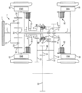
during highway
driving and lower than desirable for highway driving in order to provide
adequate city driving
performance. This compromise and the design of typical EVTs also means that
exceedingly high
torques are often applied to clutches within the EVT. Further, when operating
purely under
battery power without the propulsive force from the engine, the maximum final
drive speed is
limited by the component speeds of a planetary gear set within the EVT. Thus,
in a battery
electric vehicle or when used in a range-extended electric vehicle, EVTs
typically have a limited
top speed resulting from the city and highway gearing compromise made within
the EVT.
Therefore, an EVT is desirable that provides greater kinematic variability
within the transmission
while minimizing the compromise between city and highway performance.
[0004] In addition, a typical EVT is subject to increased mechanical and
electrical losses
during highway operation. These losses stem from internal friction within the
EVT as well as
1
CA 02811523 2013-03-15
WO 2012/037013
PCT/US2011/051187
the inherent electrical losses of using one electrical motor as a generator to
power a second
electrical motor. Thus, an EVT is desirable that provides for fixed gear
operation with efficient
highway cruising.
[0005] A typical EVT has limited reverse gear operation and relies solely
upon one of its
electric motors to provide reverse propulsion. This is problematic during
situations in which
electric power may be limited such as in extremely hot or cold climates. If
electric power fails or
provides inadequate propulsive force, the vehicle is simply unable to move in
reverse. Thus, an
EVT is needed that allows the EVT to harness the propulsive force of the
engine for reverse gear
operation, or that can use both electric motors of the EVT to provide reverse
propulsion if battery
power is adequate.
[0006] It is, therefore, desirable to provide an EVT that keeps the engine
operating within
its efficiency and/or power range while also providing satisfactory city and
highway
perfoimance. It is also desirable to provide an EVT with reduced clutch
torques and improved
functionality in range-extended electric vehicles and battery electric
vehicles. It is also desirable
to provide an EVT with a fixed gear operating capability for improved highway
cruising and a
reverse gear for vehicle reverse operation.
BRIEF SUMMARY OF THE INVENTION
[0007] In an example embodiment, a transmission having a transmission input
shaft and
a planetary gear set is provided. The planetary gear set includes a first sun
gear, at least two first
pinion gears meshed with the first sun gear, a first carrier coupled to the at
least two first pinion
gears and the transmission input shaft, and a first ring gear meshed with the
at least two first
pinion gears. The transmission also includes a first electric motor coupled to
the first sun gear, a
second electric motor coupled to the first ring gear, and an output gear. The
output gear is
selectively coupled to the first electric motor to provide a first
transmission gear ratio, and the
output gear is selectively coupled to the second electric motor to provide a
second transmission
gear ratio.
[00081 In another example embodiment, a transmission having a transmission
input shaft
and a planetary gear set is provided. The planetary gear set includes a sun
gear, a plurality of
pinion gears meshed with the sun gear, a carrier coupled to the plurality of
pinion gears and the
2
CA 02811523 2013-03-15
WO 2012/037013
PCT/US2011/051187
transmission input shaft, and a ring gear meshed with the plurality of pinion
gears. The
transmission also includes a first electric motor coupled to the sun gear, a
second electric motor
coupled to the ring gear, and an output gear. The output gear is selectively
coupled to the first
electric motor to provide a first transmission gear ratio, and the output gear
is selectively coupled
to the second electric motor to provide a second transmission gear ratio.
[0009] In another example embodiment, a transmission having a transmission
input shaft
and a planetary gear set is provided. The planetary gear set includes a sun
gear, a plurality of
pinion gears meshed with the sun gear, a carrier coupled to the plurality of
pinion gears and the
transmission input shaft, and a ring gear meshed with the plurality of pinion
gears. The
transmission also includes a first electric motor coupled to the sun gear, a
second electric motor
coupled to the ring gear, and an output gear. The output gear is selectively
coupled to the first
electric motor, and the output gear is selectively coupled to the second
electric motor.
[0010] One advantage of the disclosed embodiments is that an improved
input-split
planetary gear set configuration is provided for the multi-mode EVT. The multi-
mode EVT may
be operated in its desired efficiency and/or performance range more
frequently. Further, the
transmission reduces clutch torques and provides improved functionality in
range-extended
electric vehicles and battery electric vehicles. The multi-mode EVT is
provided with a fixed
gear operating capability for improved highway cruising and a reverse gear for
vehicle reverse
operation.
BRIEF DESCRIPTION OF THE DRAWINGS
[0011] The technology is illustrated and described herein with reference
to the various
drawings, in which like reference numbers denote like method steps ancUor
system components,
and in which:
[0012] FIG. 1 illustrates an example multi-mode electrically variable
transmission having
multiple operating modes according to an embodiment disclosed herein;
[0013] FIG. 2 illustrates an example multi-mode electrically variable
transmission having
multiple operating modes according to another embodiment disclosed herein;
3
CA 02811523 2013-03-15
WO 2012/037013
PCT/US2011/051187
[00141 FIG. 3 is a graph showing the rotations per minute of a first
electric motor, second
electric motor, output driver gear, and the engine of the multi-mode
electrically variable
transmission of FIG. 2 plotted against the output rotations per minute of the
final drive;
[00151 FIG. 4 is a lever diagram of a first electric motor, second
electric motor, the
engine and output gear of the multi-mode electrically variable transmission of
FIG. 2;
[0016] FIG. 5 illustrates an example multi-mode electrically variable
transmission having
multiple operating modes according to another embodiment disclosed herein;
[0017] FIG. 6 illustrates an example multi-mode electrically variable
transmission having
multiple operating modes according to another embodiment disclosed herein;
[0018] FIG. 7 is a lever diagram of a first electric motor, second
electric motor, the
engine and output driver gear of the multi-mode electrically variable
transmission of FIG. 6;
[0019] FIG. 8 is a graph showing the rotations per minute of a first
electric motor, second
electric motor, output driver gear, and the engine of the multi-mode
electrically variable
transmission of FIG. 6 plotted against the output rotations per minute of the
final drive;
[0020] FIG. 9 illustrates an example multi-mode electrically variable
transmission having
multiple operating modes according to another embodiment disclosed herein;
[00211 FIG. 10 is a lever diagram of a first electric motor, second
electric motor, the
engine and output driver gear of the multi-mode electrically variable
transmission of FIG. 9;
[00221 FIG. 11 is a graph showing the rotations per minute of a first
electric motor,
second electric motor, output driver gear, and the engine of the multi-mode
electrically variable
transmission of FIG. 9 plotted against the output rotations per minute of the
final drive;
[00231 FIG. 12 illustrates an example multi-mode electrically variable
transmission
having multiple operating modes according to another embodiment disclosed
herein;
[00241 FIG. 13 illustrates an example multi-mode electrically variable
transmission
having multiple operating modes according to another embodiment disclosed
herein; and
4
CA 02811523 2013-03-15
WO 2012/037013
PCT/US2011/051187
[0025] FIG. 14 illustrates an example multi-mode electrically variable
transmission
having multiple operating modes according to another embodiment disclosed
herein.
DETAILED DESCRIPTION OF THE PREFERRED EMBODIMENTS
[0026] FIG. 1 illustrates an example multi-mode electrically variable
transmission
("MM-EVT") having multiple operating modes according to an embodiment
disclosed herein.
The MM-EVT is coupled to an engine 1 by a transmission input shaft 2. The
transmission input
shaft 2 is also coupled to a carrier 21 of an input-split planetary gear set
7. The input-split
planetary gear set 7 is a conventional planetary gear set as would be readily
understood by one of
ordinary skill in the art and includes a sun gear 22, a plurality of pinion
gears 23 and a ring gear
24. The pinion gears 23 are rotatably mounted on the carrier 21. Each
planetary gear 23 is
continuously meshed with the sun gear 22 and the ring gear 24. The sun gear 22
is non-rotatably
coupled by a shaft 3 to electric motor A 91 ("EMA"). The ring gear 24 is non-
rotatably coupled
to electric motor B 92 ("EMB").
[0027] EMB 92 is also non-rotatably coupled to a first clutch mechanism 81.
The first
clutch mechanism 81 selectively non-rotatably couples EMB 92 to a shaft 5. The
shaft 5 is non-
rotatably coupled to a first driver gear 11. EMB 92 is also non-rotatably
coupled to a shaft 4.
The shaft 4 is non-rotatably coupled to a synchronizer mechanism 88. The
synchronizer
mechanism 88 is longitudinally movable along the shaft 4 and may be moved into
contact with
reverse driver gear 13, thereby locking the reverse driver gear 13 to the
shaft 4. EMA 92 is non-
rotatably coupled to a second clutch mechanism 82. The second clutch mechanism
82
selectively non-rotatably couples EMA 92 to shaft 6. Shaft 6 is non-rotatably
coupled to a
second driver gear 12.
[0028] The MM-EVT also includes an output shaft 36 non-rotatably coupled to
a first
driven gear 31 continuously meshed with the first driver gear 11, second
driven gear 32
continuously meshed with the second driver gear 12, and a reverse driven gear
33 continuously
meshed with a reverse idler gear 14, which is continuously meshed with the
reverse driver gear
13. An output gear 34 is non-rotatably coupled to the output shaft 36. The
output gear 34 is
continuously meshed with a final drive output 35 that distributes propulsive
force from the MM-
EVT.
CA 02811523 2013-03-15
WO 2012/037013
PCT/US2011/051187
[0029] The MM-EVT of FIG. 1 may be configured for operation in several
different
modes. For operation of the MM-EVT in a first transmission gear ratio with the
engine 1 and
EMB 92 providing propulsive force and EMA 91 generating electrical power, the
first clutch
mechanism 81 is activated, the second clutch mechanism 82 is deactivated, and
the synchronizer
mechanism 88 is kept out of contact with the reverse driver gear 13. To switch
the MM-EVT to
operate in a second transmission gear ratio from the first transmission gear
ratio, the MM-EVT is
first switched to operate in a fixed gear state by adjusting the RPM of EMA 91
to match the
RPM of shaft 6. Once the RPM of EMA 91 approximates the RPM of shaft 6, the
second clutch
mechanism 82 is activated in addition to the already activated first clutch
mechanism 81, and the
synchronizer mechanism 88 is kept out of contact with the reverse driver gear
13. When the
MM-EVT enters fixed gear operation from the first transmission gear ratio, the
engine I and
EMB 92 are providing propulsive force while EMA 91 is generating electrical
power. To switch
to operate in the second transmission gear ratio, EMB 92 is switched to a
generating mode and
EMA 91 is switched to provide propulsive force. To complete the switch of the
MM-EVT into
the second transmission gear ratio with the engine 1 and EMA 91 providing
propulsive force and
EMB 92 generating electrical power, the second clutch mechanism 82 remains
activated, the first
clutch mechanism 81 is deactivated, and synchronizer mechanism 88 is kept out
of contact with
the reverse driver gear 13. To switch the MM-EVT to operate in the first
transmission gear ratio
from the second transmission gear ratio, the MM-EVT is first switched to
operate in a fixed gear
state by adjusting the RPM of EMB 92 to match the RPM of shaft 5. Once the RPM
of EMB 92
approximates the RPM of shaft 5, the first clutch mechanism 81 is activated in
addition to the
already activated second clutch mechanism 82, and the synchronizer mechanism
88 is kept out of
contact with the reverse driver gear 13. When the MM-EVT enters fixed gear
operation from the
second transmission gear ratio, the engine 1 and EMA 91 are providing
propulsive force while
EMB 92 is generating electrical power. To switch to operate in the first
transmission gear ratio,
EMA 91 is switched to a generating mode and EMB 92 is switched to provide
propulsive force.
To complete the switch to the first transmission gear ratio, the first clutch
mechanism 81 remains
activated, the second clutch mechanism 82 is deactivated, and synchronizer
mechanism 88 is
kept out of contact with the reverse driver gear 13. For operation of the MM-
EVT in reverse, the
first clutch mechanism 81 and second clutch mechanism 82 are deactivated and
the synchronizer
6
CA 02811523 2013-03-15
WO 2012/037013
PCT/US2011/051187
mechanism 88 is moved into contact with the reverse driver gear 13, thereby
locking the reverse
driver gear 13 to shaft 4.
[0030] FIG. 2 illustrates an example multi-mode electrically variable
transmission
("MM-EVT") having multiple operating modes according to another embodiment
disclosed
herein. The MM-EVT is coupled to an engine 201 by a transmission input shaft
202. The
transmission input shaft 202 is also coupled to a carrier 221 of an input-
split planetary gear set
207. The input-split planetary gear set 207 is a conventional planetary gear
set as would be
readily understood by one of ordinary skill in the art and includes a sun gear
222, a plurality of
pinion gears 223 and a ring gear 224. The pinion gears 223 are rotatably
mounted on the carrier
221. Each planetary gear 223 is continuously meshed with the sun gear 222 and
the ring gear
224. The sun gear 222 is non-rotatably coupled by a shaft 203 to electric
motor A 291 ("EMA").
The ring gear 224 is non-rotatably coupled to electric motor B 292 ("EMB").
[0031] EMB 292 is also non-rotatably coupled to a second clutch mechanism
282 by a
shaft 204. A first clutch mechanism 281 selectively non-rotatably couples EMB
292 and shaft
204 to a shaft 205. Shaft 205 is non-rotatably coupled to a first driver gear
211. Shaft 204 is
also non-rotatably coupled to a synchronizer mechanism 288. The synchronizer
mechanism 288
is longitudinally movable along the shaft 204 and may be moved into contact
with a reverse
driver gear 213, thereby locking the reverse driver gear 213 to the shaft 204.
EMA 292 is non-
rotatably coupled to a second clutch mechanism 282. The second clutch
mechanism 282
selectively non-rotatably couples EMA 292 to shaft 206. Shaft 206 is non-
rotatably coupled to a
second driver gear 212.
[0032] The MM-EVT also includes an output shaft 236 non-rotatably coupled
to a first
driven gear 231 continuously meshed with the first driver gear 211, second
driven gear 232
continuously meshed with the second driver gear 212, and reverse driven gear
233 continuously
meshed with a reverse idler gear 214, which is continuously meshed with the
reverse driven gear
213. An output gear 234 is non-rotatably coupled to the output shaft 236. The
output gear 234 is
continuously meshed with a final drive output 235 that distributes propulsive
force from the
MM-EVT.
7
CA 02811523 2013-03-15
WO 2012/037013 PCT/US2011/051187
[0033] The MM-EVT of FIG. 2 may be configured for operation in several
different
modes. For operation of the MM-EVT in a first transmission gear ratio with the
engine 201 and
EMB 292 providing propulsive force and EMA 291 generating electrical power,
the first clutch
mechanism 281 is activated, the second clutch mechanism 282 is deactivated,
and the
synchronizer mechanism 288 is kept out of contact with the reverse driver gear
213. To switch
the MM-EVT to operate in a second transmission gear ratio from the first
transmission gear ratio,
the MM-EVT is first switched to operate in a fixed gear state by adjusting the
RPM of EMA 291
to match the RPM of shaft 206. Once the RPM of EMA 291 approximates the RPM of
shaft
206, the second clutch mechanism 282 is activated in addition to the already
activated first clutch
mechanism 281, and the synchronizer mechanism 288 is kept out of contact with
the reverse
driver gear 213. When the MM-EVT enters fixed gear operation from the first
transmission gear
ratio, the engine 201 and EMB 292 are providing propulsive force while EMA 291
is generating
electrical power. To switch to operate in the second transmission gear ratio,
EMB 292 is
switched to a generating mode and EMA 291 is switched to provide propulsive
force. To
complete the switch of the MM-EVT into the second transmission gear ratio with
the engine 201
and EMA 291 providing propulsive force and EMB 292 generating electrical
power, the second
clutch mechanism 282 remains activated, the first clutch mechanism 281 is
deactivated, and the
synchronizer mechanism 288 is kept out of contact with the reverse driver gear
213. To switch
the MM-EVT to operate in the first transmission gear ratio from the second
transmission gear
ratio, the MM-EVT is first switched to operate in a fixed gear state by
adjusting the RPM of
EMB 292 to match the RPM of shaft 205. Once the RPM of EMB 292 approximates
the RPM of
shaft 205, the first clutch mechanism 281 is activated in addition to the
already activated second
clutch mechanism 282, and the synchronizer mechanism 288 is kept out of
contact with the
reverse driver gear 213. When the MM-EVT enters fixed gear operation from the
second
transmission gear ratio, the engine 201 and EMA 291 are providing propulsive
force while EMB
292 is generating electrical power. To switch to operate in the first
transmission gear ratio, EMA
291 is switched to a generating mode and EMB 292 is switched to provide
propulsive force. To
complete the switch to the first transmission gear ratio, the first clutch
mechanism 281 remains
activated, the second clutch mechanism 282 is deactivated, and synchronizer
mechanism 288 is
kept out of contact with the reverse driver gear 213. For operation of the MM-
EVT in reverse,
the first clutch mechanism 281 and second clutch mechanism 282 are deactivated
and the
8
CA 02811523 2013-03-15
WO 2012/037013
PCT/US2011/051187
synchronizer mechanism 288 is moved into contact with the reverse driver gear
213, thereby
locking the reverse driver gear 213 to shaft 204.
[0034] FIG. 3 is a graph showing the rotations per minute of a first
electric motor
("EMA"), second electric motor ("EMB"), output driver gear ("OUTPUT GEAR"),
and the
engine ("ENGINE") of the multi-mode electrically variable transmission ("MM-
EVT") of FIG. 2
plotted against the output rotations per minute of the final drive. The MM-EVT
is operated in
the first transmission gear ratio at final drive RPM between zero and Ni, the
fixed gear mode at
final drive RPM equal to Ni, and the second transmission gear ratio at final
drive RPM greater
than Ni. Throughout operation, the RPM of the engine remain constant and the
RPM of the
output driver gear increases proportionally with the increase in the final
drive RPM. At final
drive RPM between zero and Ni, the RPM of the EMB increases proportionally
with the
increase in the final drive RPM and the RPM of EMA decreases proportionally
with the increase
in the final drive RPM. At final drive RPM greater than Ni, the transmission
transitions into the
second transmission gear ratio and the RPM of EMB decreases proportionally
with the increase
in the final drive RPM and the RPM of EMA increases proportionally with the
increase in the
final drive RPM.
[0035] FIG. 4 is a lever diagram of a first electric motor ("EMA SPEED" in
FIG. 4),
second electric motor ("EMB SPEED"), the engine ("ENGINE SPEED") and output
gear
("OUTPUT GEAR") of the multi-mode electrically variable transmission ("MM-
EVT") of FIG.
2. The lever diagram of FIG. 4 represents the MM-EVT operating in a fixed gear
state. Lever
Li represents the input-split planetary gear set 207, lever D1 represents the
first transmission
gear ratio, and lever D2 represents the second transmission gear ratio. The
engine 201 RPM
causes EMA 291 to rotate at a first RPM and EMB 292 to rotate at a second RPM.
The first
clutch mechanism 281 ("Cl") couples EMB 292 to the first driver gear 211 on
lever Dl. The
rotation of EMB 292 on lever DI causes the first driver gear 211 and output
gear 234 to rotate at
a third RPM. The second clutch mechanism 282 ("C2) couples EMA 291 to the
second driver
gear 212 on lever D2. The rotation of EMA 291 on lever D2 causes the second
driver gear 212
and output gear 234 to rotate at the third RPM. The RPM of the first driver
gear 211 on lever D1
and second driver gear 212 on lever D2 are equal to the RPM of the output gear
234 when the
MM-EVT is operated in a fixed gear state.
9
CA 02811523 2013-03-15
WO 2012/037013
PCT/US2011/051187
[0036] FIG. 5 illustrates an example multi-mode electrically variable
transmission
("MM-EVT") having multiple operating modes according to another embodiment
disclosed
herein. The MM-EVT is coupled to an engine 501 by a transmission input shaft
502. The
transmission input shaft 502 is also coupled to a carrier 521 of an input-
split planetary gear set
507. The input-split planetary gear set 507 is a conventional planetary gear
set as would be
readily understood by one of ordinary skill in the art and includes a sun gear
522, a plurality of
pinion gears 523 and a ring gear 524. The pinion gears 523 are rotatably
mounted on the carrier
521. Each planetary gear 523 is continuously meshed with the sun gear 522 and
the ring gear
524. The sun gear 522 is non-rotatably coupled by a shaft 503 to electric
motor A 591 ("EMA")
and a second synchronizer mechanism 584. The second synchronizer mechanism 584
is
longitudinally movable along the shaft 503 and may be moved into contact with
a second driver
gear 512, thereby locking the second driver gear 512 to the shaft 503. The
ring gear 524 is non-
rotatably coupled to a shaft 505.
[0037] A first driver gear 511 is non-rotatably coupled to the shaft 505.
The first driver
gear 511 is continuously meshed with an EMB layshaft driven gear 542 of an EMB
reduction
gear set 508. The EMB reduction gear set 508 further includes an EMB layshaft
540 non-
rotatably coupled to the EMB layshaft driven gear 542 and an EMB layshaft
driver gear 541. The
EMB layshaft driver gear 541 is continuously meshed with a reverse driver gear
513. The
reverse driver gear 513 is non-rotatably coupled by a shaft 504 to electric
motor B 592 ("EMB").
[0038] The MM-EVT also includes an output shaft 536 non-rotatably coupled
to a first
synchronizer mechanism 588, an output gear 534, and a second driven gear 532.
The first driven
gear 531 and reverse driven gear 533 are rotatably coupled to the output shaft
536. The first
synchronizer mechanism 588 is longitudinally movable along the output shaft
536 and may be
moved into contact with the first driven gear 531, thereby, locking the first
driven gear 531 to the
output shaft 536. The first synchronizer mechanism 588 may also be moved into
contact with
the reverse driven gear 533, thereby, locking the reverse driven gear 533 to
the output shaft 536.
= The first driven gear 531 is continuously meshed with the first driver
gear 511, the second driven
gear 532 is continuously meshed with the second driver gear 512, and the
reverse driven gear
533 continuously meshed with a reverse idler gear 514 which is continuously
meshed with the
CA 02811523 2013-03-15
WO 2012/037013
PCT/US2011/051187
reverse driver gear 513. The output gear 534 is continuously meshed with a
final drive output
535 that distributes propulsive force from the MM-EVT.
[0039] The MM-EVT of FIG. 5 may be configured for operation in several
different
modes. For operation of the MM-EVT in a first transmission gear ratio with the
engine 501 and
EMB 592 providing propulsive force and EMA 591 generating electrical power,
the first
synchronizer mechanism 588 is moved into contact with the first driven gear
531, thereby
locking it to the output shaft 536 and the second synchronizer mechanism 584
is kept out of
contact with the second driver gear 512. To switch the MM-EVT to operate in a
second
transmission gear ratio from the first transmission gear ratio, the MM-EVT is
first switched to
operate in a fixed gear state by adjusting the RPM of EMA 591 to match the RPM
of the second
driver gear 512. Once the RPM of EMA 591 approximates the RPM of the second
driver gear
512, the second synchronizer mechanism 584 is moved into contact with the
second driver gear
512, thereby locking it to shaft the shaft 503, while the first synchronizer
mechanism 588
remains in contact with the first driven gear 531. When the MM-EVT enters
fixed gear
operation from the first transmission gear ratio, the engine 501 and EMB 592
are providing
propulsive force while EMA 591 is generating electrical power. To switch to
operate in the
second transmission gear ratio, EMB 592 is switched to a generating mode and
EMA 591 is
switched to provide propulsive force. To complete the switch of the MM-EVT
into the second
transmission gear ratio with the engine 501 and EMA 591 providing propulsive
force and EMB
592 generating electrical power, the first synchronizer mechanism 588 is moved
out of contact
with the first driven gear 531 while the second synchronizer mechanism 584
remains in contact
with the second driver gear 512. To switch the MM-EVT to operate in the first
transmission gear
ratio from the second transmission gear ratio, the MM-EVT is first switched to
operate in the
fixed gear state by adjusting the RPM of EMB 592 to cause the RPM of the first
driven gear 531
to match the RPM of the output shaft 536. Once the RPM of the first driven
gear 531
approximates the RPM of the output shaft 536, the first synchronizer mechanism
588 is moved
into contact with the first driven gear 531, thereby locking it to the output
shaft 536, while the
second synchronizer mechanism 584 remains in contact with the second driver
gear 512. When
the MM-EVT enters fixed gear operation from the second transmission gear
ratio, the engine 501
and EMA 591 are providing propulsive force while EMB 592 is generating
electrical power. To
switch to operate in the first transmission gear ratio, EMA 591 is switched to
a generating mode
11
CA 02811523 2013-03-15
WO 2012/037013
PCT/US2011/051187
and EMB 592 is switched to provide propulsive force. To complete the switch of
the MM-EVT
into the first transmission gear ratio with the engine 501 and EMB 592
providing propulsive
force and EMA 591 generating electrical power, the second synchronizer
mechanism 584 is
moved out of contact with the second driver gear 512 while the first
synehronizer mechanism
588 remains in contact with the first driven gear 531. For operation of the MM-
EVT in reverse,
the first synchronizer mechanism 588 is moved into contact with the reverse
driven gear 533,
thereby locking it to the output shaft 536, and the second synchronizer
mechanism 584 is kept
out of contact with the second driver gear 512.
[0040] FIG. 6 illustrates an example multi-mode electrically variable
transmission
("MM-EVT") having multiple operating modes according to another embodiment
disclosed
herein. The MM-EVT is coupled to an engine 601 by a transmission input shaft
602. The
transmission input shaft 602 is coupled to a carrier 621 of an input-split
planetary gear set 607.
The input-split planetary gear set 607 is a conventional planetary gear set as
would be readily
understood by one of ordinary skill in the art and includes a sun gear 622, a
plurality of pinion
gears 623 and a ring gear 624. The pinion gears 623 are rotatably mounted on
the carrier 621.
Each planetary gear 623 is continuously meshed with the sun gear 622 and the
ring gear 624.
The sun gear 622 is non-rotatably coupled by a shaft 603 to electric motor A
691 ("EMA") and a
second synchronizer mechanism 689. The ring gear 624 is non-rotatably coupled
by a shaft 605
to an EMB reduction gear set 608 and a first synchronizer mechanism 688.
[0041] The EMB reduction gear set 608 includes a planetary gear set having
an EMB
gear set sun gear 651, EMB gear set pinion gears 652, EMB gear set ring gear
653, and EMB
gear set carrier 654. The EMB gear set carrier 654 is non-rotatably coupled to
'the shaft 605.
The planetary gear set is a conventional planetary gear set as would be
readily understood by one
of ordinary skill in the art. The EMB gear set pinion gears 652 are rotatably
mounted on the
EMB gear set carrier 654. Each EMB gear set planetary gear 652 is continuously
meshed with
the EMB gear set sun gear 651 and the EMB gear set ring gear 653. The EMB gear
set ring gear
653 is non-rotatably coupled to the transmission housing 693. The EMB gear set
sun gear 651 is
non-rotatably coupled by a shaft 604 to electric motor B 692 ("EMB").
[0042] The first synchronizer mechanism 688 is longitudinally movable along
the shaft
605 and may be moved into contact with an output driver gear 638, thereby
locking the output
12
CA 02811523 2013-03-15
WO 2012/037013
PCT/US2011/051187
driver gear 638 to the shaft 605. The second synchronizer mechanism 689 is
longitudinally
movable along the shaft 603 and may be moved into contact with the output
driver gear 638,
thereby locking the output driver gear 638 to the shaft 603. The output driver
gear 638 is
continuously meshed with an output driven gear 637 non-rotatably coupled to an
output layshaft
636. An output gear 634 is also non-rotatably coupled to the output layshaft
636. The output
gear 634 is continuously meshed with a final drive output 635 that distributes
propulsive force
from the MM-EVT.
[0043] The MM-EVT of FIG. 6 may be configured for operation in several
different
modes. For operation of the MM-EVT in a first transmission gear ratio with the
engine 601 and
EMB 692 providing propulsive force and EMA 691 generating electrical power,
the first
synchronizer mechanism 688 is moved into contact with the output driver gear
638, thereby
locking it to the shaft 605. To switch the MM-EVT to operate in a second
transmission gear
ratio from the first transmission gear ratio, the MM-EVT is first switched to
operate in a fixed
gear state by adjusting the RPM of EMA 691 to match the RPM of the output
driver gear 638.
Once the RPM of EMA 691 approximates the RPM of the output driver gear 638,
the second
synchronizer mechanism 689 is moved into contact with the output driver gear
638, thereby
locking it to shaft the shaft 603, while the first synchronizer mechanism 688
remains in contact
with the output driver gear 638. When the MM-EVT enters fixed gear operation
from the first
transmission gear ratio, the engine 601 and EMB 692 are providing propulsive
force while EMA
691 is generating electrical power. To switch to operate in the second
transmission gear ratio,
EMB 692 is switched to a generating mode and EMA 691 is switched to provide
propulsive
force. To complete the switch of the MM-EVT into the second transmission gear
ratio with the
engine 601 and EMA 691 providing propulsive force and EMB 692 generating
electrical power,
the first synchronizer mechanism 688 is moved out of contact with the output
driver gear 638
while the second synchronizer mechanism 689 remains in contact with the output
driver gear
638. To switch the MM-EVT to operate in the first transmission gear ratio from
the second
transmission gear ratio, the MM-EVT is first switched to operate in the fixed
gear state by
adjusting the RPM of EMB 692 to cause the RPM of the shaft 605 to match the
RPM of the
output driver gear 638. Once the RPM of the shaft 605 approximates the RPM of
the output
driver gear 638, the first synchronizer mechanism 688 is moved into contact
with the output
driver gear 638, thereby locking it to shaft 605, while the second
synchronizer mechanism 689
13
CA 02811523 2013-03-15
WO 2012/037013
PCT/US2011/051187
remains in contact with the output driver gear 638. When the MM-EVT enters
fixed gear
operation from the second transmission gear ratio, the engine 601 and EMA 691
are providing
propulsive force while EMB 692 is generating electrical power. To switch to
operate in the first
transmission gear ratio, EMA 691 is switched to a generating mode and EMB 692
is switched to
provide propulsive force. To complete the switch of the MM-EVT into the first
transmission
gear ratio with the engine 601 and EMB 692 providing propulsive force and EMA
691
generating electrical power, the second synchronizer mechanism 689 is moved
out of contact
with the output driver gear 638 while the first synchronizer mechanism 688
remains in contact
with the output driver gear 638.
[0044] FIG. 7 is a lever diagram of the first electric motor ("EMA
SPEED"), second
electric motor ("EMB SPEED"), the engine ("ENGINE SPEED") and output driver
gear
("OUTPUT GEAR") of the multi-mode electrically variable transmission ("MM-
EVT") of FIG.
6. The lever diagram of FIG. 7 represents the MM-EVT operating in a fixed gear
state. The
lever Li represents the input-split planetary gear set 607 and the lever L2
represents the EMB
reduction gear set 608. Referring to the lever Li, the engine 601 RPM causes
EMA 691 and the
output driver gear 638 to all rotate at a first RPM. Referring to the lever
L2, the EMB gear set
ring gear 653 is fixed to the transmission housing 693 and EMB 692 is coupled
to the sun gear
651 and rotates at a second RPM. The EMB gear set carrier 654 is coupled to
the output driver
gear 638 and causes the output driver gear 638 to rotate at the first RPM.
[0045] FIG. 8 is a graph showing the rotations per minute of the first
electric motor
("EMA"), second electric motor ("EMB"), output driver gear ("OUTPUT GEAR"),
and the
engine ("ENGINE") of the multi-mode electrically variable transmission ("MM-
EVT") of FIG. 6
plotted against the output rotations per minute of the final drive. The MM-EVT
is operated in
the first transmission gear ratio at final drive RPM between zero and Ni, the
fixed gear mode at
final drive RPM equal to Ni, and the second transmission gear ratio at final
drive RPM greater
than Ni. Throughout operation, the RPM of the engine remain constant and the
RPM of the
output driver gear increases proportionally with the increase in the final
drive RPM. At final
drive RPM between zero and Ni, the RPM of EMB increases proportionally with
the increase in
the final drive RPM and the RPM of EMA decreases proportionally with the
increase in the final
drive RPM. At final drive RPM greater than Ni, the transmission transitions
into the second
14
CA 02811523 2013-03-15
WO 2012/037013
PCT/US2011/051187
transmission gear ratio and the RPM of EMB decreases proportionally with the
increase in the
final drive RPM and the RPM of EMA increases proportionally with the increase
in the final
drive RPM. In addition, at final drive RPM greater than Ni, the RPM of the
output driver gear
equals the RPM of EMA.
[0046] FIG. 9 illustrates an example multi-mode electrically variable
transmission
("MM-EVT") having multiple operating modes according to another embodiment
disclosed
herein. The MM-EVT is coupled to an engine 901 by a transmission input shaft
902. The
transmission input shaft 902 is also coupled to a carrier 921 of an input-
split planetary gear set
907. The input-split planetary gear set 907 is a conventional planetary gear
set as would be
readily understood by one of ordinary skill in the art and includes a sun gear
922, a plurality of
pinion gears 923 and a ring gear 924. The pinion gears 923 are rotatably
mounted on the carrier
921. Each planetary gear 923 is continuously meshed with the sun gear 922 and
the ring gear
924. The sun gear 922 is non-rotatably coupled by a shaft 903 to electric
motor A 991 ("EMA")
and a second clutch mechanism 982. The ring gear 924 is non-rotatably coupled
by a shaft 905
to an EMB reduction gear set 908 and a first clutch mechanism 981.
[0047] The EMB reduction gear set 908 includes a planetary gear set having
an EMB
gear set sun gear 951, EMB gear set pinion gears 952, EMB gear set ring gear
953, and EMB
gear set carrier 954. The EMB gear set ring gear 953 is non-rotatably coupled
to the shaft 905.
The planetary gear set is a conventional planetary gear set as would be
readily understood by one
of ordinary skill in the art. The EMB gear set pinion gears 952 are rotatably
mounted on the
EMB gear set carrier 954. Each EMB gear set planetary gear 952 is continuously
meshed with
the EMB gear set sun gear 951 and the EMB gear set ring gear 953. The EMB gear
set carrier
954 is non-rotatably coupled to the transmission housing 993. The EMB gear set
sun gear 951 is
non-rotatably coupled by a shaft 904 to electric motor B 992 ("EMB").
[0048] The first clutch mechanism 981 selectively couples an output driver
gear 938 to
shaft 905 and the second clutch mechanism 982 selectively couples the output
driver gear 938 to
shaft 903. The output driver gear 938 is continuously meshed with an output
driven gear 937
non-rotatably coupled to an output layshaft 936. An output gear 934 is also
non-rotatably
coupled to the output layshaft 936. The output gear 934 is continuously meshed
with a final
drive output 935 that distributes propulsive force from the MM-EVT.
CA 02811523 2013-03-15
WO 2012/037013
PCT/US2011/051187
[0049] The MM-EVT of FIG. 9 may be configured for operation in several
different
modes. For operation of the MM-EVT in a first transmission gear ratio with the
engine 901 and
EMB 992 providing propulsive force and EMA 991 generating electrical power,
the first clutch
mechanism 981 is activated and the second clutch mechanism 982 is deactivated.
To switch the
MM-EVT to operate in a second transmission gear ratio from the first
transmission gear ratio, the
MM-EVT is first switched to operate in a fixed gear state by adjusting the RPM
of EMA 991 to
match the RPM of the output driver gear 938. Once the RPM of EMA 991
approximates the
RPM of the output driver gear 938, the second clutch mechanism 982 is
activated and in addition
to the already activated first clutch mechanism 981. When the MM-EVT enters
fixed gear
operation from the first transmission gear ratio, the engine 901 and EMB 992
are providing
propulsive force while EMA 991 is generating electrical power. To switch to
operate in the
second transmission gear ratio, EMB 992 is switched to a generating mode and
EMA 991 is
switched to provide propulsive force. To complete the switch of the MM-EVT
into the second
transmission gear ratio with the engine 901 and EMA 991 providing propulsive
force and EMB
992 generating electrical power, the first clutch mechanism 981 is deactivated
while the second
clutch mechanism 982 remains activated. To switch the MM-EVT to operate in the
first
transmission gear ratio from the second transmission gear ratio, the MM-EVT is
first switched to
operate in the fixed gear state by adjusting the RPM of EMB 992 to cause the
RPM of the shaft
905 to match the RPM of the output driver gear 938. Once the RPM of the shaft
905
approximates the RPM of the output driver gear 938, the first clutch mechanism
981 is activated
in addition to the already activated second clutch mechanism 982. When the MM-
EVT enters
fixed gear operation from the second transmission gear ratio, the engine 901
and EMA 991 are
providing propulsive force while EMB 992 is generating electrical power. To
switch to operate
in the first transmission gear ratio, EMA 991 is switched to a generating mode
and EMB 992 is
switched to provide propulsive force. To complete the switch of the MM-EVT
into the first
transmission gear ratio with the engine 901 and EMB 992 providing propulsive
force and EMA
991 generating electrical power, the second clutch mechanism 982 is
deactivated while the first
clutch mechanism 981 remains activated.
[0050] FIG. 10 is a lever diagram of the first electric motor ("EMA
SPEED"), second
electric motor ("EMB SPEED"), the engine ("ENGINE SPEED") and output driver
gear
("OUTPUT GEAR") of the multi-mode electrically variable transmission ("MM-
EVT") of FIG.
16
CA 02811523 2013-03-15
WO 2012/037013
PCT/US2011/051187
9. The lever diagram of FIG. 10 represents the MM-EVT operating in a fixed
gear state. Lever
Li represents the input-split planetary gear set 907 and lever L2 represents
the EMB reduction
gear set 908. Referring to lever Li, the engine 901 RPM causes EMA 991 and the
output driver
gear 938 to all rotate at a first RPM. Referring to lever L2, the EMB gear set
carrier 954 of L2 is
fixed to the transmission housing 993 and EMB 992 is coupled to the sun gear
951 and rotates at
a second RPM. The EMB gear set ring gear 953 is coupled to the output driver
gear 938 and
causes the output driver gear 938 to rotate at the first RPM.
[0051] FIG. 11 is a graph showing the rotations per minute of a first
electric motor
("EMA"), second electric motor ("EMB"), output driver gear ("OUTPUT GEAR"),
and the
engine ("ENGINE") of the multi-mode electrically variable transmission ("MM-
EVT") of FIG. 9
plotted against the output rotations per minute of the final drive. The MM-EVT
is operated in
the first transmission gear ratio at final drive RPM between zero and N1, the
fixed gear mode at
final drive RPM equal to Ni, and the second transmission gear ratio at final
drive RPM greater
than Ni. Throughout operation, the RPM of the engine remain constant and the
RPM of the
output driver gear increases proportionally with the increase in the final
drive RPM. At final
drive RPM between zero and Ni, the RPM of EMB becomes increasingly negative
proportionally with the increase in the final drive RPM and the RPM of EMA
decreases
proportionally with the increase in the final drive RPM. At final drive RPM
greater than N1, the
transmission transitions into the second transmission gear ratio and the RPM
of EMB becomes
decreasingly negative proportionally with the increase in the final drive RPM
and the RPM of
EMA increases proportionally with the increase in the final drive RPM. In
addition, at final
drive RPM greater than Ni, the RPM of the output driver gear equals the RPM of
EMA.
[0052] FIG. 12 illustrates an example multi-mode electrically variable
transmission
("MM-EVT") having multiple operating modes according to another embodiment
disclosed
herein. The MM-EVT is coupled to an engine 1201 by a transmission input shaft
1202. The
transmission input shaft 1202 is also coupled to a carrier 1221 of an input-
split planetary gear set
1207. The input-split planetary gear set 1207 is a conventional planetary gear
set as would be
readily understood by one of ordinary skill in the art and includes a sun gear
1222, a plurality of
pinion gears 1223 and a ring gear 1224. The pinion gears 1223 are rotatably
mounted on the
carrier 1221. Each planetary gear 1223 is continuously meshed with the sun
gear 1222 and the
17
CA 02811523 2013-03-15
WO 2012/037013
PCT/US2011/051187
ring gear 1224. The sun gear 1222 is non-rotatably coupled by a shaft 1203 to
electric motor A
1291 ("EMA") and a second synchronizer mechanism 1289. The ring gear 1224 is
non-rotatably
coupled by a shaft 1205 to an EMB reduction gear set 1208 and a first
synchronizer mechanism
1288.
[0053] The EMB reduction gear set 1208 includes a planetary gear set having
an EMB
gear set sun gear 1251, EMB gear set pinion gears 1252, EMB gear set ring gear
1253, and EMB
gear set carrier 1254. The EMB gear set carrier 1254 is non-rotatably coupled
to the shaft 1205.
The planetary gear set is a conventional planetary gear set as would be
readily understood by one
of ordinary skill in the art. The EMB gear set pinion gears 1252 are rotatably
mounted on the
EMB gear set carrier 1254. Each EMB gear set planetary gear 1252 is
continuously meshed with
the EMB gear set sun gear 1251 and the EMB gear set ring gear 1253. The EMB
gear set ring
gear 1253 is non-rotatably coupled to the transmission housing 1293 and a
shaft 1206. The EMB
gear set sun gear 1251 is non-rotatably coupled by a shaft 1204 to electric
motor B 1292
("EMB").
[0054] The first synchronizer mechanism 1288 is longitudinally movable
along the shaft
1205 and may be moved into contact with an output driver gear 1238, thereby
locking a output
driver gear 1238 to the shaft 1205. The first synchronizer mechanism 1288 may
also be moved
into contact with shaft 1206, thereby locking the first synchronizer mechanism
1288 and shaft
1205 to the transmission housing 1293 to improve the operational efficiency of
the MM-EVT.
The second synchronizer mechanism 1289 is longitudinally movable along the
shaft 1203 and
may be moved into contact with the output driver gear 1238, thereby locking
the output driver
gear 1238 to the shaft 1203. The output driver gear 1238 is continuously
meshed with an output
driven gear 1237 non-rotatably coupled to an output layshaft 1236. An output
gear 1234 is also
non-rotatably coupled to the output layshaft 1236. The output gear 1234 is
continuously meshed
with a final drive output 1235 that distributes propulsive force from the MM-
EVT.
[0055] The MM-EVT of FIG. 12 may be configured for operation in several
different
modes. For operation of the MM-EVT in a first transmission gear ratio with the
engine 1201 and
EMB 1292 providing propulsive force and EMA 1291 generating electrical power,
the first
synchronizer mechanism 1288 is moved into contact with the output driver gear
1238, thereby
locking it to shaft 1205. To switch the MM-EVT to operate in a second
transmission gear ratio
18
CA 02811523 2013-03-15
WO 2012/037013
PCT/US2011/051187
from the first transmission gear ratio, the MM-EVT is first switched to
operate in a fixed gear
state by adjusting the RPM of EMA 1291 to match the RPM of the output driver
gear 1238.
Once the RPM of EMA 1291 approximates the RPM of the output driver gear 1238,
the second
synchronizer mechanism 1289 is moved into contact with the output driver gear
1238, thereby
locking the output driver gear 1238 to shaft 1203, while the first
synchronizer mechanism 1288
remains in contact with the output driver gear 1238. When the MM-EVT enters
fixed gear
operation from the first transmission gear ratio, the engine 1201 and EMB 1292
are providing
propulsive force while EMA 1291 is generating electrical power. To switch to
operate in the
second transmission gear ratio, EMB 1292 is switched to a generating mode and
EMA 1291 is
switched to provide propulsive force. To complete the switch of the MM-EVT
into the second
transmission gear ratio with the engine 1201 and EMA 1291 providing propulsive
force and
EMB 1292 generating electrical power, the first synchronizer mechanism 1288 is
moved out of
contact with the output driver gear 1238 while the second synchronizer
mechanism 1289 remains
in contact with the output driver gear 1238. To switch the MM-EVT to operate
in the first
transmission gear ratio from the second transmission gear ratio, the MM-EVT is
first switched to
operate in the fixed gear state by adjusting the RPM of EMB 1292 to cause the
RPM of the shaft
. 1205 to match the RPM of the output driver gear 1238. Once the RPM of the
shaft 1205
approximates the RPM of the output driver gear 1238, the first synchronizer
mechanism 1288 is
moved into contact with the output driver gear 1238, thereby locking the
output driver gear 1238
to shaft 1205, while the second synchronizer mechanism 1289 remains in contact
with the output
driver gear 1238. When the MM-EVT enters fixed gear operation from the second
transmission
gear ratio, the engine 1201 and EMA 1291 are providing propulsive force while
EMB 1292 is
generating electrical power. To switch to operate in the first transmission
gear ratio, EMA 1291
is switched to a generating mode and EMB 1292 is switched to provide
propulsive force. To
complete the switch of the MM-EVT into the first transmission gear ratio with
the engine 1201
and EMB 1292 providing propulsive force and EMA 1291 generating electrical
power, the
second synchronizer mechanism 1289 is moved out of contact with the output
driver gear 1238
while the first synchronizer mechanism 1288 remains in contact with the output
driver gear
1238. For operation of the MM-EVT with EMB 1292 grounded, the first
synchronizer
mechanism 1288 is moved into contact with shaft 1206, thereby locking shaft
1206 and EMB
1292 to the transmission housing 1293.
19
CA 02811523 2013-03-15
WO 2012/037013
PCT/US2011/051187
[0056] FIG. 13 illustrates an example multi-mode electrically variable
transmission
("MM-EVT") having multiple operating modes according to another embodiment
disclosed
herein. The MM-EVT is coupled to an engine 1301 by a transmission input shaft
1302. The
transmission input shaft 1302 is also coupled to a carrier 1321 of an input-
split planetary gear set
1307. The input-split planetary gear set 1307 is a conventional planetary gear
set as would be
readily understood by one of ordinary skill in the art and includes a sun gear
1322, a plurality of
pinion gears 1323 and a ring gear 1324. The pinion gears 1323 are rotatably
mounted on the
carrier 1321. Each planetary gear 1323 is continuously meshed with the sun
gear 1322 and the
ring gear 1324. The sun gear 1322 is non-rotatably coupled by a shaft 1303 to
electric motor A
1391 ("EMA") and a second synchronizer mechanism 1389. The ring gear 1324 is
non-rotatably
coupled to a shaft 1305.
[0057] Shaft 1305 is non-rotatably coupled to a reverse driver gear 1313
and a first
synchronizer mechanism 1388. The reverse driver gear 1313 is continuously
meshed with an
EMB layshaft driven gear 1342 of an EMB reduction gear set 1308. The EMB
reduction gear set
1308 further includes an EMB layshaft 1340 non-rotatably coupled to the EMB
layshaft driven
gear 1342 and an EMB layshaft driver gear 1341. The EMB layshaft driver gear
1341 is
continuously meshed with an EMB driven gear 1343. The EMB driven gear 1343 is
non-
rotatably coupled by a shaft 1304 to EMB 1392.
[0058] The first synchronizer mechanism 1388 is longitudinally movable
along the shaft
1305 and may be moved into contact with an output driver gear 1338, thereby
locking the output
driver gear 1338 to the shaft 1305. The second synchronizer mechanism 1389 is
longitudinally
movable along the shaft 1303 and may be moved into contact with the output
driver gear 1338,
thereby locking the output driver gear 1338 to the shaft 1303. The output
driver gear 1338 is
continuously meshed with an output driven gear 1337 non-rotatably coupled to
an output
layshaft 1336. An output gear 1334 and third synchronizer mechanism 1390 are
also non-
rotatably coupled to the output layshaft 1336. A reverse driven gear 1333 is
rotatably coupled to
the output layshaft 1336. The reverse driven gear 1333 is continuously meshed
with a reverse
idler gear 1314 which is continuously meshed with the reverse driver gear
1313. The third
synchronizer mechanism 1390 is longitudinally movable along the output
layshaft 1336 and may
be moved into contact with the reverse driven gear 1333, thereby locking the
reverse driven gear
CA 02811523 2013-03-15
WO 2012/037013
PCT/US2011/051187
1333 to the output layshaft 1336. The output gear 1334 is continuously meshed
with a final
drive output 1335 that distributes propulsive force from the MM-EVT.
[00591 The MM-EVT of FIG. 13 may be configured for operation in several
different
modes. For operation of the MM-EVT in a first transmission gear ratio with the
engine 1301 and
EMB 1392 providing propulsive force and EMA 1391 generating electrical power,
the first
synchronizer mechanism 1388 is moved into contact with the output driver gear
1338, the second
synchronizer mechanism 1389 is kept out of contact with the output driver gear
1338, and the
third synchronizer mechanism 1390 is kept out of contact with the reverse
driven gear 1333. To
switch the MM-EVT to operate in a second transmission gear ratio from the
first transmission
gear ratio, the MM-EVT is first switched to operate in a fixed gear state by
adjusting the RPM of
EMA 1391 to match the RPM of the output driver gear 1338. Once the RPM of EMA
1391
approximates the RPM of the output driver gear 1338, the second synchronizer
mechanism 1389
is moved into contact with the output driver gear 1338, thereby locking it to
shaft 1303, while the
first synchronizer mechanism 1388 remains in contact with the output driver
gear 1338. When
the MM-EVT enters fixed gear operation from the first transmission gear ratio,
the engine 1301
and EMB 1392 are providing propulsive force while EMA 1391 is generating
electrical power.
To switch to operate in the second transmission gear ratio, EMB 1392 is
switched to a generating
mode and EMA 1391 is switched to provide propulsive force. To complete the
switch of the
MM-EVT into the second transmission gear ratio with the engine 1301 and EMA
1391 providing
propulsive force and EMB 1392 generating electrical power, the first
synchronizer mechanism
1388 is moved out of contact with the output driver gear 1338 while the second
synchronizer
mechanism 1389 remains in contact with the output driver gear 1338. To switch
the MM-EVT
to operate in the first transmission gear ratio from the second transmission
gear ratio, the MM-
EVT is first switched to operate in the fixed gear state by adjusting the RPM
of EMB 1392 to
cause the RPM of shaft 1305 to match the RPM of the output driver gear 1338.
Once the RPM
of shaft 1305 approximates the RPM of the output driver gear 1338, the first
synchronizer
mechanism 1388 is moved into contact with the output driver gear 1338, thereby
locking it to
shaft 1305, while the second synchronizer mechanism 1389 remains in contact
with the output
driver gear 1338. When the MM-EVT enters fixed gear operation from the second
transmission
gear ratio, the engine 1301 and EMA 1391 are providing propulsive force while
EMB 1392 is
generating electrical power. To switch to operate in the first transmission
gear ratio, EMA 1391
21
CA 02811523 2013-03-15
WO 2012/037013
PCT/US2011/051187
is switched to a generating mode and EMB 1392 is switched to provide
propulsive force. To
complete the switch of the MM-EVT into the first transmission gear ratio with
the engine 1301
and EMB 1392 providing propulsive force and EMA 1391 generating electrical
power, the
second synchronizer mechanism 1389 is moved out of contact with the output
driver gear 1338
while the first synchronizer mechanism 1388 remains in contact with the output
driver gear
1338. For operation of the MM-EVT in reverse, the first synchronizer mechanism
1388 and
second synchronizer mechanism 1389 remain out of contact with the output
driver gear 1338
while the third synchronizer mechanism 1390 is moved into contact with the
reverse driven gear
1333, thereby locking the reverse driven gear 1333 to the output shaft 1336.
[0060] FIG. 14 illustrates an example multi-mode electrically variable
transmission
("MM-EVT") having multiple operating modes according to another embodiment
disclosed
herein. The MM-EVT is coupled to an engine 1401 by a transmission input shaft
1402. The
transmission input shaft 1402 is also coupled to a carrier 1421 of an input-
split planetary gear set
1407. The input-split planetary gear set 1407 is a conventional planetary gear
set as would be
readily understood by one of ordinary skill in the art and includes a sun gear
1422, a plurality of
pinion gears 1423 and a ring gear 1424. The pinion gears 1423 are rotatably
mounted on the
carrier 1421. Each planetary gear 1423 is continuously meshed with the sun
gear 1422 and the
ring gear 1424. The sun gear 1422 is non-rotatably coupled by a shaft 1403 to
electric motor A
1491 ("EMA") and a second synchronizer mechanism 1489. The ring gear 1424 is
non-rotatably
coupled by a shaft 1405 to an EMB reduction gear set 1408 and a first
synchronizer mechanism
1488.
[0061] The EMB reduction gear set 1408 includes an EMB layshaft driven gear
1442
non-rotatably coupled to the shaft 1405. The EMB layshaft driven gear 1442 is
continuously
meshed with an EMB layshaft driver gear 1441 non-rotatably coupled to an EMB
layshaft 1440.
The EMB layshaft 1440 is non-rotatably coupled to electric motor B 1492
("EMB").
[0062] The first synchronizer mechanism 1488 is longitudinally movable
along the shaft
1405 and may be moved into contact with an output driver gear 1438, thereby
locking the output
driver gear 1438 to the shaft 1405. The second synchronizer mechanism 1489 is
longitudinally
movable along the shaft 1403 and may be moved into contact with the output
driver gear 1438,
thereby locking the output driver gear 1438 to the shaft 1403. The output
driver gear 1438 is
22
CA 02811523 2013-03-15
WO 2012/037013
PCT/US2011/051187
continuously meshed with an output driven gear 1437 non-rotatably coupled to
an output
layshaft 1436. An output gear 1434 is also non-rotatably coupled to the output
layshaft 1436.
The output gear 1434 is continuously meshed with a final drive output 1435
that distributes
propulsive force from the MM-EVT.
[0063] The MM-EVT of FIG. 14 may be configured for operation in several
different
modes. For operation of the MM-EVT in a first transmission gear ratio with the
engine 1401 and
EMB 1492 providing propulsive force and EMA 1491 generating electrical power,
the first
synchronizer mechanism 1488 is moved into contact with the output driver gear
1438, thereby
locking it to shaft 1405. To switch the MM-EVT to operate in a second
transmission gear ratio
from the first transmission gear ratio, the MM-EVT is first switched to
operate in a fixed gear
state by adjusting the RPM of EMA 1491 to match the RPM of the output driver
gear 1438.
Once the RPM of EMA 1491 approximates the RPM of the output driver gear 1438,
the second
synchronizer mechanism 1489 is moved into contact with the output driver gear
1438, thereby
locking it to shaft 1403, while the first synchronizer mechanism 1488 remains
in contact with the
output driver gear 1438. When the MM-EVT enters fixed gear operation from the
first
transmission gear ratio, the engine 1401 and EMB 1492 are providing propulsive
force while
EMA 1491 is generating electrical power. To switch to operate in the second
transmission gear
ratio, EMB 1492 is switched to a generating mode and EMA 1491 is switched to
provide
propulsive force. To complete the switch of the MM-EVT into the second
transmission gear
ratio with the engine 1401 and EMA 1491 providing propulsive force and EMB
1492 generating
electrical power, the first synchronizer mechanism 1488 is moved out of
contact with the output
driver gear 1438 while the second synchronizer mechanism 1489 remains in
contact with the
output driver gear 1438. To switch the MM-EVT to operate in the first
transmission gear ratio
from the second transmission gear ratio, the MM-EVT is first switched to
operate in the fixed
gear state by adjusting the RPM of EMB 1492 to cause the RPM of the shaft 1405
to match the
RPM of the output driver gear 1438. Once the RPM of the shaft 1405
approximates the RPM of
the output driver gear 1438, the first synchronizer mechanism 1488 is moved
into contact with
the output driver gear 1438, thereby locking it to shaft 1405, while the
second synchronizer
mechanism 1489 remains in contact with the output driver gear 1438. When the
MM-EVT
enters fixed gear operation from the second transmission gear ratio, the
engine 1401 and EMA
1491 are providing propulsive force while EMB 1492 is generating electrical
power. To switch
23
CA 02811523 2013-03-15
WO 2012/037013
PCT/US2011/051187
to operate in the first transmission gear ratio, EMA 1491 is switched to a
generating mode and
EMB 1492 is switched to provide propulsive force. To complete the switch of
the MM-EVT
into the first transmission gear ratio with the engine 1401 and EMB 1492
providing propulsive
force and EMA 1491 generating electrical power, the second synchronizer
mechanism 1489 is
moved out of contact with the output driver gear 1438 while the first
synchronizer mechanism
1488 remains in contact with the output driver gear 1438.
[0064] While the disclosed MM-EVTs of FIGs. 1, 2, 5, 6, 9, and 12-14 are
shown with
two forward gear ratios and, in some embodiments, a reverse/third gear ratio,
the disclosed MM-
EVT is not so limited. Any number of forward and/or reverse gear ratios and
corresponding
clutches and synchronizer mechanisms may be included within the MM-EVT as
desired. The
gear ratios and corresponding final drive ratios may be selected to be any
desired underdrive or
overdrive ratio as would be readily apparent to one of skill in the art to
achieve the desired
engine efficiency, power band, and/or vehicle perfoimance. In addition, any
type of clutching
mechanism or arrangement may be utilized within the MM-EVT as would be known
to one of
skill in the art. For instance, the MM-EVT may utilize dry clutches, wet
clutches, multi-plate
clutches, dog clutches, synchronizer mechanisms, dual clutches as found in a
conventional dry
dual clutch transmission, or any other known clutching mechanism to achieve
the disclosed
clutching action. The clutching mechanisms may be located on any of the shafts
within the MM-
EVT. Further, planetary gear sets may be used in place of the layshaft
arrangement. For
example, referring to FIG. 1, the first driver gear 11/first driven gear 31
combination may be
replaced by a first planetary gear set and the second driver gear 12/second
driven gear 32
combination may be replaced by a second planetary gear set.
[0065] The switching between the first transmission gear ratio, fixed gear
operation, and
second transmission gear ratio can be performed at synchronous speeds, as
disclosed above, or at
non-synchronous speeds with the help of the oncoming clutch. When the
switching is perfoimed
at non-synchronous speeds, the oncoming clutch overcomes and equalizes any
difference in
rotational speed of the clutched components. In addition, while some
embodiments of the MM-
EVT are not disclosed with a dedicated reverse gear, this is not to say that
the MM-EVT of these
embodiments cannot be operated in reverse. Rather, one or both of the electric
motors A and B
24
CA 02811523 2013-03-15
WO 2012/037013
PCT/US2011/051187
may be operated in a direction opposite to its typical direction of operation
for forward
propulsion in order to provide reverse operation for the MM-EVT.
[0066] In addition, the MM-EVT may utilize both motors to launch the
vehicle. In one
embodiment, the vehicle may be launched by reversing electric motor B while
electric motor A
is connected to the output gear and operated in the typical direction for
forwards vehicle
propulsion. It is also contemplated that electric motor A, or a combination of
electric motor A
and electric motor B may be used to start the vehicle engine. It should also
be understood that
while the specification refers to an electric motor B reduction gear set, the
electric motor B
reduction gear set need not be reduction gearing. Instead, the electric motor
B reduction gear set
may increase the output ratio of electric motor B or achieve any other desired
output gear ratio
for electric motor B.
[0067] One advantage of the disclosed embodiments is that an improved
input-split
planetary gear set configuration is provided. The multi-mode EVT may be
operated in its
desired efficiency and/or performance range more frequently. Further, the
transmission reduces
clutch torques and provides improved functionality in range-extended electric
vehicles and
battery electric vehicles. The multi-mode EVT is provided with a fixed gear
operating capability
for improved highway cruising and a reverse gear for vehicle reverse
operation.
[0068] Although this technology has been illustrated and described herein
with reference
to preferred embodiments and specific examples thereof, it will be readily
apparent to those of
ordinary skill in the art that other embodiments and examples can perfolin
similar functions
and/or achieve like results. All such equivalent embodiments and examples are
within the spirit
and scope of the technology and are intended to be covered by the following
claims.