Note: Descriptions are shown in the official language in which they were submitted.
CA 02811589 2013-03-15
WO 2012/040643 PCT/US2011/053120
PERCUTANEOUSLY DELIVERABLE HEART OR BLOOD VESSEL VALVE WITH
FRAME HAVING ABLUMINALLY SITUATED TISSUE MEMBRANE
FIELD
The present invention relates to the field of medical devices, and more
particularly, to a
percutaneously deliverable heart valve and to a percutaneously deliverable
blood vessel valve.
BACKGROUND
Heart valve disease is a common degenerative condition that compromises
physiologic
function and causes limiting symptoms and threat to life in millions of
patients all over the
world. There are various underlying causes, but malfunction of heart valves is
ultimately
expressed as insufficient conduction of blood through the plane of the valve
due to narrowing of
the anatomic pathway (stenosis), or as incompetent closure that allows blood
to return back
through the valve again, thereby reducing the effective forward conduction of
blood through the
valve (insufficiency or regurgitation). These hemodynamic states lead to 1)
deficiency of
cardiac output and 2) adverse loads on the pumping chambers of the heart, both
of which in turn
lead to functional compromise of the patient and often premature death unless
effectively
corrected.
Definitive corrective treatment of heart valve disease is conventionally
performed by
open-chest surgical techniques, wherein the valve is manipulated, repaired, or
replaced with a
prosthetic valve under direct vision. Heart valve surgery is performed in
hundreds of thousands
of cases yearly world-wide, but carries a high burden of cost, morbidity, and
mortality,
especially in susceptible patients who may be elderly or otherwise
physiologically compromised
by collateral disease. Further, the costs and resource requirements of the
surgical enterprise
restrict the availability of heart valve replacement to many more patients all
over the world.
In pursuit of alternatives to heart valve surgery, over the last ten years a
number of
development programs have brought percutaneous, trans-catheter implantation of
prosthetic
heart valves into commercial use in the European Union (EU) and into pivotal
clinical trials in
the United States of America. Initial clinical experience in the EU was
directed toward patients
who had critical aortic valve stenosis, but were deemed to be at unacceptably
high risk for open-
heart surgical valve replacement. In several thousand such cases, utilizing
both balloon-
expandable and self-expanding designs in two separate programs, percutaneous
heart valve
replacement (PHVR) was shown to be feasible and possibly competitive with
surgery in selected
patients with 12-18 month mortality rates of about 25%. Grube E., et al.,
Progress and Current
Status of Percutaneous Aortic Valve Replacement: Results of Three Device
Generations of the
Core Valve Revalving System, Circ. Cardiovasc Intervent. 2008;1:167-175.
CA 02811589 2013-03-15
WO 2012/040643 PCT/US2011/053120
Typically, the current percutaneous heart valve (PHV) designs, including the
commercialized Medtronic CoreValve and the Edwards Lifesciences Sapien valves,
comprise a
biological membrane forming the operating leaflets of the valve, mounted
within the interior of a
metal frame, that is then collapsed onto a delivery catheter or balloon, and
then constrained
within an outer sheath. After an initial dilation of the diseased valve with a
large balloon, this
assembly is then advanced to the plane of the valve and deployed by self-
expansion or by
balloon expansion.
PHV designs are confronted by several central challenges. More particularly,
the
functioning valve leaflets are typically constructed of flexible and
compressible tissue
membrane valve members attached by sutures to a surrounding stent frame that
together must be
durable, yet of sufficiently low mass to allow for passage in collapsed form
into the patient's
body through an anatomic pathway¨a peripheral artery, for example¨of limited
diameter,
leading to the implantation site within the central circulation system. This
condition favors
simple, yet robust design geometries.
Secondly, the PHV in its implanted operating configuration must emulate both
the
opening mechanics and the closing mechanics of the native heart valve¨two
differing
geometries and mechanical forms afforded by the native anatomy of the aortic
valve, for
example, but with the limitation that the PHV must effectively embody both
within its physical
and operational envelope without the benefit of the grossly different
anatomical forms native to
the aortic valve.
As a practical matter, the measures of effective function are simple¨the
pressure
gradient during forward passage of blood across the valve must be as low as
possible, typically 5
- 10 mmHg or less. While achieving this, the "success" of operation in the
closed configuration,
wherein the leaflets are pressed together along lines of apposition by the
pressure of the blood
pumped beyond the valve, would also appear to be simply measured by the amount
of retrograde
blood passage back into the pumping chamber¨the "regurgitation" or "leakage."
However, since this closed phase of valve function is the phase in which the
principal
force loads are applied to the valve membrane leaflets, and since the manner
in which the design
of the valve distributes these forces determines the durability of the valve,
the real measure of
the valve's closing function is best understood by how well the design
minimizes and distributes
the force loads on the valve leaflets. To date, this problem has not been
sufficiently addressed.
In the field of blood vessel diseases certain conditions may be advantageously
treated by
insertion of valves into an affected patient's blood vessels. Currently no
such valve devices are
available, though investigation of this approach has suggested potential
clinical utility for blood
vessel valves, and in particular for valves to be inserted into the vein
system for particular
- 2 -
CA 02811589 2013-03-15
WO 2012/040643 PCT/US2011/053120
conditions. In the first example, insufficiency of the inlet
(atrioventricular) tricuspid valve to the
right ventricle of the heart results in regurgitation of blood back into the
right atrium, which,
serving to receive blood flow returning in the veins from the entire body,
then results in turn in
suffusion and swelling (edema) of all the organs, most notably in the abdomen
and extremities,
insufficient forward conduction of blood flow from the right ventricle into
the lungs causing
compromise of pulmonary function, and ultimately pump failure of the right
heart. Collectively
these conditions are termed right heart failure, a condition that leads to
incapacity and possibly
to death if progressive and uncorrected. Often, the remedy is surgical repair
or replacement of
the tricuspid valve, but results are uncertain, damage to the right ventricle
being often
irreversible, and progressive heart failure may supervene despite technically
successful valve
surgery.
In a yet a further example, insufficiency of vein function due to the
incompetence or
destruction of intrinsic valves within the vein system leads to acute then
chronic swelling of the
veins and their dependent lymphatics and tissues. This condition can affect
the deep veins of the
body, commonly the lower extremities or pelvis, or the superficial veins of
the lower extremities
in particular, leading to progressive expansion of the veins and further
valvular incompetence, a
condition known as varicose veins. Millions of people worldwide suffer from
these conditions
and enormous funds are expended on procedures to destroy or remove these
dilated incompetent
veins. It has long been hoped that some form of implantable valve for the vein
system could
alleviate these conditions.
Several references of interest have been reviewed in preparation of the
present
disclosure. The applicants do not admit that the any one or more of the
following references
constitute citable prior art.
U.S. Patent No. 7,758,632 to Hojeibane discloses a valve construct wherein all
embodiments include stent portions that act as proximal and distal anchors
that are
interconnected by connecting members, and further include a "cantilever valve
strut" that acts as
a biasing arm to "facilitate the opening and closing of the membrane
assembly." Such
structures may disrupt the flow channel and potentially interfere with
membrane integrity when
crimping the valve to mount it on an expandable balloon. In addition, at the
point of
engagement of the tissue against the connecting members, there is relatively
intense focal stress
along the straight connecting member ¨ especially at the free edge of the
leaflet. Hojeibane
further utilizes flaps 403 and cusps 404 that may be independent components
attached to the
tubular membrane to form the membrane assembly 102. Accordingly, Hojeibane
does not
appear to use a flat sheet of membrane.
- 3 -
CA 02811589 2013-03-15
WO 2012/040643 PCT/US2011/053120
U.S. Patent No. 7,025,780 to Gabbay discloses two separate uses of a device
referred to
as a "stent." The first use is that of the stent in a surgical valve wherein
it is a supportive
structure to give shape and mechanical support to the tissue leaflets formed
upon it. This device
in Gabbay is like a surgical tissue valve. As shown in Figs. 5 and 6 of
Gabbay, the stent is
disposed outside of at least an inner tissue leaflet layer. In the second use,
as shown in Figs. 1
and 2 of Gabbay, a tissue valve of some type is disposed within an outer frame
of the vascular
stent type. In this case, the tissue layer is not disposed upon the abluminal
surface of the outer
stent frame. The reader is directed to column 1, lines 61-63 of Gabbay that
state "The prosthesis
includes a valve apparatus located within a stent apparatus to form a stented
valve." Gabbay
further references only a "valve apparatus comprising an animal pulmonic heart
valve."
Accordingly, Gabbay fails to disclose a valve formed of flat tissue membrane
wherein the tissue
membrane is attached to the abluminal surface of a frame.
U.S. Patent Application Publication No. 2006/0190074 to Hill is directed to
venous
valves, and as such, the structural embodiments shown in Hill do not appear
robust enough for
application as prosthetic heart valves, such as in the aortic valve position.
The valve material is
referred to as a "cover" comprising a matrix and "integrated flexible support
members 124" ¨
essentially a reinforcing layer applied to the matrix. While tissue sources of
"extracellular
membrane" are cited as possible sources for the matrix, the use of a single
layer tissue
membrane for the leaflets is not disclosed in Hill.
With further reference to U.S. Patent Application Publication No.
2006/0190074, Hill
also does not describe how the cover material is attached to the frame to
achieve a sufficiently
robust construct for utilization as a prosthetic heart valve. That is, while
Hill generally discusses
attachment of the cover to the frame at Paragraph [0072] using a variety of
possible fasteners,
none are shown and described relative to the frame. Of particular relevance is
that while Hill
mentions coupling the cover 108 to the frame 102 at connection regions 132 and
134, there is no
mention of coupling the cover 108 to the arcuate portions of the frame members
126 that lead to
the connection regions 132 and 134.
Accordingly, there is a need to address the shortcomings discussed above.
SUMMARY
It is to be understood that the present invention includes a variety of
different versions or
embodiments, and this Summary is not meant to be limiting or all-inclusive.
This Summary
provides some general descriptions of some of the embodiments, but may also
include some
more specific descriptions of other embodiments.
As noted above, the real measure of the valve's closing function is best
understood by
how well the design minimizes and distributes the force loads on the valve
leaflets. This
- 4 -
CA 02811589 2013-03-15
WO 2012/040643 PCT/US2011/053120
condition favors design geometries in which closing apposition of the leaflet
surfaces is
achieved with a minimum of traction force on the valve attachment points to
the frame. To this
end the inventive valve achieves this and other operational advantages by
situating the operating
tissue membrane to the exterior/abluminal surface of the valve frame rather
than the
interior/luminal space of the frame and by distributing the operating force
loads of the valve
along the curved edges forming the distal (downstream to flow direction) end
of the frame. No
other known percutaneously implantable or even surgical valve bioprosthesis
utilizes this
configuration with the tissue membrane mounted entirely upon the abluminal
aspect of the
device frame which carries the closed valve force loads along the distal
formed edge of the
frame corresponding to the lines of attachment of the leaflet membrane.
Accordingly, in at least one embodiment, an implantable prosthetic valve is
provided that
includes a frame and tissue membrane. Advantageously, the tissue membrane
resides to the
exterior of the frame along an axial length of the frame in the flow direction
of the implantable
prosthetic valve when implanted. That is, the membrane sheet resides entirely
exterior or
abluminal to the frame when the valve is in the fully open condition and at
least at all attachment
points when the valve is partly or completely closed. The attachment points
may comprise a
plurality of sutures that are used to attach the membrane sheet to the frame
at a variety of
locations, such as at one or more intersections of the frame.
The descriptions of the inventive valve are focused for the purpose of
technical
specification upon the replacement heart valve application, but will apply as
well to the blood
vessel valve device. By way of example, in addition to use of the valves
described herein to
replace heart valves, methods and devices described herein also provide for
transcatheter
implantation of a valve into the inferior vena cava (the principal conduit
vein from the lower
body inserting into the right heart) to act as an upstream substitute in part
for the tricuspid valve.
Such a valve device would be advantageously designed to be low in mass with
large effective
orifice. The inventive valve device is proposed as suitable to this purpose.
Alternatively, the
condition of right heart failure may be treated in part by interposing valves
into the vein system
farther upstream in the venous return flow, such as in the subclavian or
principal iliac veins.
Accordingly, in at least one embodiment, an implantable prosthetic valve is
provided for
controlling, at least in part, a flow of blood, comprising:
a frame having an abluminal frame surface, a proximal end, and a distal end,
wherein the
proximal end is situated at an inlet end of the frame relative to the flow of
blood when
implanted, and wherein the distal end is situated at an outlet end of the
frame relative to the flow
of blood when implanted, the frame having a tubular flow path through its
interior; and
- 5 -
CA 02811589 2013-03-15
WO 2012/040643 PCT/US2011/053120
a tissue membrane attached to the frame, the tissue membrane having an
interior surface
and an exterior surface;
wherein the interior surface of the tissue membrane is situated exterior the
abluminal
frame surface of the frame between the proximal end and distal end of the
frame, when the valve
is in the fully open position, the interior surface of the tissue membrane
intersecting the tubular
flow path of the frame when the tissue membrane is located in a closed
position.
A percutaneous, trans-catheter prosthetic valve for implantation in a patient
is provided,
comprising:
a frame including an abluminal surface extending between a proximal end of the
frame
and a distal end of the frame, wherein the frame is collapsible and expandable
and adapted for
trans-catheter delivery; and
a biocompatible tissue material mounted to the abluminal surface of the frame
to form a
plurality of valve leaflets, wherein an entire interior surface of the
biocompatible tissue material
between the proximal end of the frame and the distal end of the frame resides
radially exterior to
the abluminal surface of the frame:
(a) at all points of attachment; and
(b) when the plurality of valve leaflets are in an operationally fully open
position.
In at least one embodiment the frame comprises a metal alloy substantially
configured as
tubular stent member. In at least one embodiment a proximal portion of the
frame includes a
ring. In at least one embodiment a proximal portion of the frame comprises a
circumferential
zig-zag of wire. In at least one embodiment a proximal portion of the frame
includes a lattice.
In at least one embodiment the lattice is circumferentially continuous. In at
least one
embodiment the lattice is circumferentially discontinuous. In at least one
embodiment a distal
end of the frame includes two or more areas of axial continuity with the
proximal end, wherein
the two or more areas of axial continuity comprise axially oriented
projections. In at least one
embodiment the frame further comprises a distally positioned stabilization
framework
comprising at least one of circumferential or radial continuity with the
axially oriented
projections. In at least one embodiment the frame includes two or more regions
of
circumferential discontinuity through which operating leaflets of the
biocompatible tissue
material move radially inward and outward in closing and opening operation,
respectively. In at
least one embodiment the biocompatible tissue material between the proximal
end of the frame
and the distal end of the frame resides substantially adjacent the abluminal
surface of the frame.
In at least one embodiment the biocompatible tissue material does not contact
a luminal surface
of the frame. In at least one embodiment an exterior surface of the
biocompatible tissue material
does not contact a luminal surface of the frame.
- 6 -
CA 02811589 2013-03-15
WO 2012/040643 PCT/US2011/053120
In accordance with at least one embodiment, the frame can be a closed cell
lattice type
construct of circumferentially corrugated/sinusoidal/zig-zag rings. In
accordance with at least
one embodiment, the frame can be a wire loop with axial loops forming a
support for each
commissure. In at least one embodiment, the frame includes a proximal portion,
wherein at least
some of the abluminal surface of the proximal portion includes a tissue sheet
attached thereto.
In at least one embodiment, a prosthetic valve for implantation in a patient
is provided,
comprising:
a frame including an abluminal surface extending between a proximal edge of
the frame
and a distal edge of the frame, the distal edge undulating axially to define
at least two areas of
circumferential discontinuity in the frame, wherein the frame is collapsible
and expandable and
adapted for trans-catheter delivery; and
a single layer of a biocompatible membrane material mounted to the abluminal
surface of
the frame to form leaflet portions, wherein the leaflet portions are
collocated with the at least
two areas of circumferential discontinuity in the frame.
In at least one embodiment the leaflet portions are attached to the frame at
least along
curved frame members formed by the distal edge of the frame and corresponding
to the radially
outward boundaries of the leaflet cusps.
In at least one embodiment, no portion of the biocompatible membrane material
is
mounted to an interior surface of the frame. In at least one embodiment, the
frame comprises a
metal alloy substantially configured as tubular stent member. In at least one
embodiment, a
proximal portion of the frame includes a lattice to which the biocompatible
membrane material
is circumferentially mounted entirely upon the abluminal aspect of the tubular
stent member. In
at least one embodiment, at least some proximal portion of the frame does not
include
biocompatible membrane material mounted to its luminal or abluminal surfaces.
In at least one
embodiment, the biocompatible membrane material extends between the proximal
edge and the
distal edge of the frame. In at least one embodiment, a distal portion of the
frame further
includes a distally extending stabilizing framework comprising a plurality of
axially oriented
support members that each extend from a distally extending frame projection
situated adjacent
the at least two areas of circumferential discontinuity in the frame. In at
least one embodiment,
the prosthetic valve further comprises a plurality of radial support members
interconnecting the
axially oriented support members. In at least one embodiment, the prosthetic
valve further
comprises a wire guide, wherein the wire guide is coaxially aligned with an
axis of the valve,
and wherein the wire guide is configured to allow for a coaxial passage of a
guide wire such that
coaxial alignment of the distally extending stabilizing framework may be
facilitated during valve
- 7 -
CA 02811589 2013-03-15
WO 2012/040643 PCT/US2011/053120
deployment. In at least one embodiment, the wire guide comprises at least one
of a ring and a
tube.
A method of preparing a percutaneous, trans-catheter prosthetic valve is also
provided,
the method comprising mounting a single layer of a biocompatible tissue
material to an
abluminal surface of a trans-catheter deliverable frame such that an interior
surface of the
biocompatible tissue material between a proximal end of the trans-catheter
deliverable frame and
a distal end of the trans-catheter deliverable frame resides radially exterior
to and substantially
adjacent the abluminal surface of the trans-catheter deliverable frame. In at
least one
embodiment the method further comprises compressing and crimping the trans-
catheter
deliverable frame, with the biocompatible tissue material mounted thereto,
upon a delivery
catheter. In at least one embodiment the method further comprises implanting
the trans-catheter
deliverable frame with the biocompatible tissue material mounted thereto into
a patient. In at
least one embodiment the trans-catheter deliverable frame comprises a stent.
In at least one
embodiment the method further comprises mounting the trans-catheter
deliverable frame and the
biocompatible tissue material mounted thereto on a mandrel.
In accordance with at least one embodiment, a method of constructing a
prosthetic valve
is provided, the method, comprising attaching a biocompatible membrane
material to a
collapsible and expandable frame to form a trans-catheter deliverable
prosthetic valve, wherein
an entire interior surface of the biocompatible membrane material is located
exterior of the
abluminal surface of the collapsible and expandable frame when leaflet
portions of the
biocompatible membrane material are in the valve's operationally open
position. In at least one
embodiment, the method further comprises associating the biocompatible
prosthetic valve with a
catheter.
In at least one embodiment, a prosthetic trans-catheter deliverable valve is
provided that
does not include one or more biasing members within the inner flow channel of
the valve. That
is, with the exception of the membrane during closure of the valve (when the
flow cycle is not
antegrade from proximal to distal through the valve), the inner flow channel
is devoid of flow
channel obstructions.
In at least one embodiment, a prosthetic trans-catheter valve includes a flat
membrane
sheet interconnected to a frame. In at least one embodiment, a flat membrane
sheet is
interconnected to the abluminal surface of a frame using a plurality of
sutures, wherein at least
some of the sutures are applied in a buttonhole suture pattern.
Various components are referred to herein as "operably associated." As used
herein,
"operably associated" refers to components that are linked together in
operable fashion, and
- 8 -
CA 02811589 2013-03-15
WO 2012/040643 PCT/US2011/053120
encompasses embodiments in which components are linked directly, as well as
embodiments in
which additional components are placed between the two linked components.
As used herein, "at least one," "one or more," and "and/or" are open-ended
expressions
that are both conjunctive and disjunctive in operation. For example, each of
the expressions "at
least one of A, B and C," "at least one of A, B, or C," "one or more of A, B,
and C," "one or
more of A, B, or C" and "A, B, and/or C" means A alone, B alone, C alone, A
and B together, A
and C together, B and C together, or A, B and C together.
As used herein, "sometime" means at some indefinite or indeterminate point of
time. So
for example, as used herein, "sometime after" means following, whether
immediately following
or at some indefinite or indeterminate point of time following the prior act.
Various embodiments of the present inventions are set forth in the attached
figures and in
the Detailed Description as provided herein and as embodied by the claims. It
should be
understood, however, that this Summary does not contain all of the aspects and
embodiments of
the one or more present inventions, is not meant to be limiting or restrictive
in any manner, and
that the invention(s) as disclosed herein is/are understood by those of
ordinary skill in the art to
encompass obvious improvements and modifications thereto.
Additional advantages of the present invention will become readily apparent
from the
following discussion, particularly when taken together with the accompanying
drawings.
BRIEF DESCRIPTION OF THE DRAWINGS
To further clarify the above and other advantages of various embodiments and
features
of the one or more present inventions, a more particular description of the
one or more present
inventions is rendered by reference to specific embodiments thereof which are
illustrated in the
appended drawings. It should be appreciated that these drawings depict only
typical
embodiments of the one or more present inventions and are therefore not to be
considered
limiting in scope. The one or more present inventions are described and
explained with
additional specificity and detail through the use of the accompanying drawings
in which:
Fig. lA is a side perspective view of an embodiment of a percutaneously
deliverable
valve with the valve membrane illustrated in a closed position;
Fig. 1B is a side elevation view of the frame suited to balloon expansion
shown in Fig.
1A;
Fig. 1C is a top plan view of the frame shown in Fig. 1B;
Fig. 1D is a side perspective view of the frame shown in Fig. 1B;
Fig. lE is a bottom perspective view of the frame shown in Fig. 1B;
- 9 -
CA 02811589 2013-03-15
WO 2012/040643 PCT/US2011/053120
Fig. 1F is a side elevation view of the frame shown in Fig. 1B, wherein the
cylindrical
frame is depicted in an "unrolled" or flat projection to illustrate the
geometry of the frame
members;
Fig. 1G is a side elevation view of another embodiment of a frame suited to
self-
expansion, wherein the cylindrical frame is depicted in an "unrolled" or flat
projection to
illustrate the geometry of the frame members;
Fig. 1H is a side elevation view of the frame shown in Fig. 1G;
Fig. 11 is a top plan view of the frame shown in Fig. 1H;
Fig. 1J is a side perspective view of the frame shown in Fig. 1H;
Fig. 1K is a bottom perspective view of the frame shown in Fig. 1H;
Fig. 1L is a side perspective view of an embodiment of a membrane sheet and
its
attachment to a frame in accordance with at least one embodiment described
herein;
Fig. 2 is a simplified distal end view of an embodiment of a frame
illustrating relative
locations of the distal ends of two distally positioned frame projections
located approximately
180 degrees apart;
Fig. 3 is a simplified distal end view of an embodiment of a frame
illustrating relative
locations of the distal ends of four distally positioned frame projections
located approximately
90 degrees apart;
Fig. 4 is a perspective view of an embodiment of a schematic of a frame having
optional
stabilization framework with circumferential supports;
Fig. 5 is a perspective view of an embodiment of a schematic of a frame having
optional
stabilization framework with radial supports;
Fig. 6 is a flow chart of a method of constructing an embodiment of a
prosthetic heart
valve as described herein;
Fig. 7 is flow chart of a method of deploying an embodiment of a prosthetic
heart valve
as described herein; and
Fig. 8 is a schematic of a heart showing an embodiment of a heart valve as
described
herein implanted within a heart.
The drawings are not necessarily to scale.
DETAILED DESCRIPTION
Embodiments of the one or more inventions described herein include one or more
devices, assemblies and/or methods related to prosthetic heart valves and to
prosthetic blood
vessel valves. A prosthetic heart valve in accordance with at least one
embodiment described
herein can be surgically implanted, such as by percutaneous, trans-catheter
delivery, to the
implantation site within the patient. One or more embodiments of the
prosthetic heart valves
- 10 -
CA 02811589 2013-03-15
WO 2012/040643 PCT/US2011/053120
described herein have application for at least aortic and pulmonary valve
positions, including for
structural defects and diseased valves. Other embodiments have application to
the vascular
system and in particular to the vein system. When reduced in scale they have
particular
application to the branch veins of the body and the extremities. The
descriptions for these
devices are effectively provided in the descriptions and specifications
provided for the inventive
percutaneously implantable heart valve device.
In at least one embodiment, biocompatible material is mounted to a frame to
form an
implantable prosthetic heart valve, and then at a later time, the implantable
prosthetic heart valve
is implanted within a patient, such as by way of a percutaneous, trans-
catheter delivery
mechanism. The percutaneously implantable heart valve is suitable for
implantation into a
native (orthotopic or ectopic) valve seat of a patient. Once implanted, the
prosthetic heart valve
serves to regulate the flow of blood associated with the patient's heart by
allowing forward
blood flow and substantially preventing backflow or valvular regurgitation.
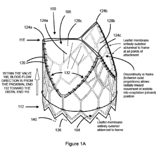
Referring now to Fig. 1A, and in accordance with at least one embodiment, an
implantable prosthetic heart valve 100 is shown that includes a frame 104 and
a single layer
membrane sheet 108, such as a biocompatible tissue membrane sheet. All or
substantially all of
the membrane sheet 108 is located on the exterior or abluminal side of the
frame 104 between
the proximal end 112 and the distal end 116 of the frame 104 when the valve
leaflets are in the
operationally fully open position and in any case at all points of attachment.
The implantable
prosthetic heart valve 100 includes a proximal (upstream) portion/margin of
membrane sheet
108 that is circumferentially attached to and residing entirely upon the
abluminal surface of the
frame 104. In at least one embodiment, the membrane sheet 108 is connected to
the frame 104
by a plurality of sutures 120. In at least one embodiment, the plurality of
sutures comprise
curved lines of attachment, axially concave to the distal end 116 of the
frame, along the frame
members at the frame's distal edge interconnecting the distally extending
frame projections
124a-c. It is to be understood that alternate ways of attaching the membrane
sheet 108 to the
frame 104 may be used, such as staples, an adhesive, an anchoring ring, one or
more bands, clips
or combinations of the foregoing.
By whatever technique of attachment, the lines of attachment by which the
arcuate
proximal basal margin of each leaflet is anchored to the arcuate distal edge
of the frame act to
distribute the force loads acting on the leaflets along these lines while in
the operationally closed
position. The securement of the leaflets in this manner is advantageous in a
high-pressure
application such as the aortic valve position. Moreover, these lines of
attachment also act to seal
the proximal basal margin of each cusp to the frame and are critical in the
case of aortic valve
implantation, because some portion of these arcuate cusp margins are likely to
be disposed
- 11 -
CA 02811589 2013-03-15
WO 2012/040643 PCT/US2011/053120
"above" (downstream) of the aortic valve annulus and without anatomic luminal
contact to the
outer aspect of the valve at this level. As such, those portions that are
disposed in the
"suprannular" position after implantation can be subject to high pressure
blood being injected
between the leaflet layer and the frame which can in turn lead to acute and
chronic compromise
of valve function. The specific form of leaflet attachment provided in the
inventive valve
addresses this problem that arises as a consequence of the abluminal/exterior
position of the
leaflet membrane in relation to the frame.
In at least one embodiment, the plurality of sutures 120 attaching the leaflet
membrane to
the distal arcuate portions of the distal edge of the frame comprise, for each
arcuate segment
144, a continuous series of "buttonhole"-technique sutures 120 wherein the
segments of suture
interconnecting the knots are disposed to the outer/abluminal surface of the
membrane. This
suture configuration advantageously imposes a small biasing effect upon the
leaflet towards the
operationally closed position.
With regard to particular material types that may be used to form the membrane
sheet, in
at least one embodiment the membrane sheet 108 forming the cusp or leaflet
portions includes a
one-piece, single layer sheet of biocompatible membrane, such as fixed
mammalian pericardium
tissue or synthetic biocompatible material such as ePTFE. In at least one
embodiment, the
membrane sheet is made from a tissue preparation process that yields a leaflet
material of
suitable strength and durability for use in a prosthetic trans-catheter
deliverable heart valve. The
content of WO 2011/109450A2 published on September 9, 2011, is incorporated
herein by
reference. Although not preferred, one or more embodiments may alternatively
comprise a
plurality of sections of membrane sheet connected to form a contiguous sheet.
In at least one embodiment, the membrane sheet is a single layer of a
substantially
homogenous material. In at least one embodiment, the membrane sheet is an
unlaminated single
layer of material. In at least one embodiment, the membrane sheet is a single
layer of material
that does not include any reinforcement, such as reinforcing fibers. In at
least one embodiment,
the membrane sheet is a single layer of treated pericardium tissue. In at
least one embodiment,
the membrane sheet is a single layer of a synthetic film.
The frame 104 may include a balloon expandable material. Alternatively, the
frame 104
may include one or more of a self expanding alloy such as nitinol, stainless
steel, cobalt
chromium, bioabsorbable metal, and non-elastic bioabsorbable plastic, such as
polylactides,
polyglycolides, their co-polymers, or polydioxanones. As further seen in Figs.
1A-1F, in at least
one embodiment the geometry of the frame 104 at the distal end 116 may include
three distally
extending frame projections 124a, 124b and 124c. This configuration is
described for
exemplary purposes. Accordingly, alternate configurations may be used,
including collapsible
- 12 -
CA 02811589 2013-03-15
WO 2012/040643 PCT/US2011/053120
and expandable percutaneously deliverable frames that include two, four, five
or any multiple
number of distally extending frame projections, provided the configuration in
combination with
the abluminally situated single layer membrane sheet 108 accommodates inward
closure of the
membrane sheet 108 sufficiently to facilitate operational closure of the valve
after being
implanted. Thus, those skilled in the art will appreciate that configurations
shown and described
herein are for purposes of enablement, and therefore, alternate configurations
from those shown
are encompassed by the claims. Consistent with the foregoing, the distally
extending frame
projections 124a-c are spaced apart around the circumference of the frame 104
as appropriate to
facilitate closure of the membrane sheet 108 when the flow cycle is not
antegrade from proximal
to distal through the valve.
Referring still to Figs. 1A-1F, in at least one embodiment, the frame 104 has
three
distally positioned inverted "v" members also referred to herein as distally
extending frame
projections 124a-c located at substantially equal angular distances apart from
each other at the
distal end 116 of the frame 104. Alternatively, each of these distally
extending frame
projections may take other forms such as a single projecting beam or an
extending loop formed
of a continuous loop of wire. Accordingly, in at least one embodiment, each
inverted "v"
member or distally extending frame projection 124a-c is about 120 degrees (at
the point or apex
of the inverted "v" members) away on either side from the other two inverted
"v" members at
the distal end 116 of the frame 104. In at least one embodiment, the inverted
"v" members serve
as attachment locations for the membrane sheet 108. In at least one
embodiment, the "v"
members are integral parts of a generally arcuate configuration of frame
members spanning the
distal frame edge between the distally extending frame projections 124a-c such
that each arcuate
span forms: 1) the radially outermost margin of a leaflet cusp; and 2) the
line of attachment of
each leaflet membrane to the distal edge of the frame. In at least one
embodiment, the proximal
end 112 of the frame 104 includes a continuous framework, although minor
axially oriented
recessions 136 in the framework are situated between the proximal-most
portions 140 of the
frame 104.
With further reference to Figs. 1B-1F, in at least one embodiment, the struts
126 forming
the inverted "v" members are located between approximately 40 to 90 degrees
apart, and more
preferably, at between approximately 50 to 70 degrees apart. By way of example
and not
limitation, as shown in the example depicted in Fig. 1F, the struts 126
forming distally extending
frame projection 124a are about 50 degrees apart. The angular values provided
herein are given
for purposes of enablement and for exemplary purposes, and are not intended to
be limiting.
Other values are possible, and such other values are within the scope of the
one or more present
inventions.
- 13 -
CA 02811589 2013-03-15
WO 2012/040643 PCT/US2011/053120
Referring again to Fig. 1A, cusp or leaflet portions 128a, 128b, and 128c
reside between
the spaced apart distally extending frame projections 124a-c. More
particularly, circumferential
discontinuities 132 in the frame 104 substantially correspond to the location
of leaflet portions
128a-c in the membrane sheet 108. That is, since the membrane sheet 108 is
situated exterior of
the frame 104, including at the frame projections 124a-c, the absence of
framework, internal
struts or other types of support for a portion of the distally located
membrane sheet 108 allows
the abluminally positioned membrane sheet 108 to occupy an area within the
flow path of the
valve 100 when the flow cycle is not antegrade from proximal to distal through
the valve.
Therefore, when flow conditions are not antegrade, the leaflet portions 128a-c
operate to close
the valve 100 because of the absence of framework circumferentially between
the distally
extending frame projections 124a-c allows the leaflet portions 128a-c of the
membrane sheet
108 to close radially inward.
Referring again to Fig. 1A, in the closed position, the leaflet portions 128a-
c reside
within the interior flow channel or lumen of the valve 100. Accordingly, the
valve 100 includes
a biocompatible membrane with a distal (downstream) portion/margin that is
attached to the
abluminal/exterior aspect of the frame 104 at at least two or more points (at
or near the apices of
the distally extending frame projections 124a-c) corresponding to two or more
valve leaflet
commissures, wherein the free edge of the membrane sheet 108 between the
points of
attachment constitutes the free edge of the valve leaflets or leaflet portions
128a-c that are free to
move radially inward into a closed position contacting the other leaflet or
leaflets, and radially
outward into an open position.
In at least one embodiment, when the leaflets 128a-c are in their open
position, the
membrane sheet 108 at the distal end 116 resides entirely to the radial
exterior of the frame 104
including at the distally extending frame projections 124a-c. Accordingly,
when flow conditions
are antegrade, the leaflets 128a-c extend radially outward from the lumen of
valve 100.
In at least one embodiment, the membrane sheet 108, including the material
constituting
the operating leaflets portions 128a-c, is exterior/abluminal to the frame 104
and may be
continuous from the leaflet portions 128a-c to the proximal end 112 of the
frame 108.
Alternatively, the membrane sheet 108 does not have to extend abluminally
along the entire
axial length of the frame 104 from the distal end 116 to the proximal end 112.
More
particularly, with limited proximal coverage, the membrane sheet 108 may only
cover a portion
of the abluminal surface of the frame 104 and reside at the distal end 116 and
extend axially
along the abluminal surface sufficiently to provide leaflet portions 128a-c
such that there is
enough membrane sheet 108 to cover the discontinuities in the frame 104 and
thus function as
leaflet portions 128a-c by moving radially inward and outward through the
frame discontinuities
- 14 -
CA 02811589 2013-03-15
WO 2012/040643 PCT/US2011/053120
132. For such a configuration the membrane sheet 108 needs to extend
proximally from the
distal end 116 a sufficient proximal distance so as to provide a sufficient
seal against
leakage/regurgitation through the frame 104. Simply stated, the membrane sheet
108 needs to
extend axially only a limited distance axially in the proximal direction, that
being to slightly
beyond the annular intersection or the valve seat formed between the abluminal
surface of the
membrane sheet 108 situated against the native tissue. Therefore, the proximal
extent of the
membrane tissue 108 beyond the intersection of the valve 100 against the
native tissue may
vary.
In at least one embodiment, the membrane sheet 108 may wrap around the
proximal edge
136 of the frame 104 so as to make a continuous inner/luminal layer within the
proximal end
112 of the frame 104. In contrast, leaving a portion of the proximal end 112
uncovered by the
membrane sheet 108 permits the frame to provide additional structure. By way
of example, the
proximal end 112 can incorporate other structural elements including flared or
hooked frame
projections for effective securement of the implanted valve. Such
configurations have
applicability to providing advantageous structure for certain valve
implantation sites, such as the
mitral valve.
In at least one embodiment, the membrane sheet 108 may wrap around the
proximal edge
of the frame 104 so as to make a continuous inner/luminal layer within the
proximal end 112 of
the frame 104. That is, the valve 100 does not require the membrane sheet 108
to extend
proximally to the proximal edge 136 of the frame 108, however, the membrane
sheet 108 may
extend proximally including to the proximal end 112, and indeed, the membrane
sheet 108 may
wrap around the proximal edge 136 to the luminal side of the frame 104.
With reference to Fig. 1F, a side elevation view of the cylindrical frame 104
is depicted
in "unrolled" flat projection to illustrate the geometry of the frame members.
The structural
differences of the frame 104 at the proximal end 112 and distal end 116 are
readily apparent,
with the areas of circumferential discontinuities 132 observable between the
distally extending
frame projections 124a-c. Each circumferential discontinuity 132 includes a
pair of generally
arcuate side portions 144 that, in at least one embodiment, include a concave
(in relation to the
distal end of the frame) shape relative to the circumferential discontinuity
132. These arcuate
spanning side portions 144 form: 1) lines of attachment of the leaflet
membrane to the frame;
and 2) the proximal/radially outermost margin of the leaflet cusp, along which
are borne the
forces exerted upon the closed leaflets. While the leaflets are attached to
the arcuate side
portions 144 as by suturing, the mobile leaflet portions and the cuff portion
of the membrane are
preferably continuous, formed of a single sheet of biocompatible membrane
disposed around
and upon the abluminal aspect of the frame. As noted above, to attach the
single layer
- 15 -
CA 02811589 2013-03-15
WO 2012/040643 PCT/US2011/053120
membrane sheet 108 to the arcuate side portions 144, sutures may be applied
using a continuous
series of "buttonhole"-technique sutures 120 wherein the segments of suture
interconnecting the
knots are disposed to the outer/abluminal surface of the membrane. This suture
configuration
advantageously imposes a small biasing effect upon the leaflet towards the
operationally closed
position.
Referring now to Figs. 1G-1K, an alternative embodiment comprising a frame
104'
suited to self-expansion is shown is shown. When comparing frame 104 to frame
104',
differences in the frame structure are apparent. However, both frames 104 and
104' have
circumferential discontinuities 132 that substantially correspond to the
location of leaflet
portions 128a-c in the membrane sheet 108. Again, since the membrane sheet 108
is situated
exterior of the frame 104', including at the frame projections 124a-c, the
absence of framework,
internal struts or other types of support for a portion of the distally
located membrane sheet 108
allows the abluminally positioned membrane sheet 108 to occupy an area within
the flow path of
the valve 100 when the flow cycle is not antegrade from proximal to distal
through the valve.
Similar to frame 104, the location of the circumferential discontinuities 132
in frame 104' allow
the leaflet portions 128a-c operate to close the valve 100 because of the
absence of framework
circumferentially between the distally extending frame projections 124a-c in
frame 104' allows
the leaflet portions 128a-c of the membrane sheet 108 to close radially
inward. Also similar to
frame 104, each circumferential discontinuity 132 includes a pair of generally
arcuate side
portions 144 that, in at least one embodiment, include a concave (in relation
to the distal end of
the frame) shape relative to the circumferential discontinuity 132. These
arcuate spanning side
portions 144 form: 1) lines of attachment of the leaflet membrane to the
frame; and 2) the
proximal/radially outermost margin of the leaflet cusp, along which are born
the forces exerted
upon the closed leaflets.
As noted above, although the embodiment shown in Fig. lA illustrates a frame
104
including three distally extending frame projections 124a-c, an alternative
number of distally
extending frame projections may be used, thereby yielding an implantable
prosthetic heart valve
with fewer or greater than three cusps. By way of example, and with reference
now to Fig. 2,
for a frame having two distally extending frame projections 124 that are
positioned at
substantially diametrically opposite sides of the frame's circumference, then
two cusps would be
provided. Similarly, and with reference now to Fig. 3, for a frame having four
distally extending
frame projections 124 that are positioned with substantially 90 degrees of
separation from one
another around the frame's circumference, then four cusps would be provided.
Referring now to Fig. 1L, a frame 104 is shown relative to a single layer
membrane sheet
108. The illustrated single layer membrane sheet 108 includes substantially
straight edges.
- 16 -
CA 02811589 2013-03-15
WO 2012/040643 PCT/US2011/053120
However, in at least one embodiment, the distal free edge of each membrane
leaflet portion has a
non-linear shape. Preferentially when the leaflet free edge is not linear, it
is cut in the shape of a
parabola with central axis of curvature aligned to the center of the free edge
of the leaflet. This
effectively extends the coaptation margin and area of the leaflet free edge
for a given leaflet
radius, reduces the pressure on the contacting leaflet areas when the valve is
closed and
improves the effectiveness of orifice sealing in closure. Accordingly, free
edge shapes for the
leaflets are cut from the corresponding edge of the flat sheet membrane before
wrapping and
mounting of the membrane upon the frame.
Alternatively, in at least one embodiment, the circumference of the membrane
exceeds
the outer circumference of the frame. The membrane is then gathered in folds
or pleats and
attached at the proximal (inlet) end of the frame so as to reduce the
effective circumference of
the membrane at the proximal end of the frame to equal that of the frame at
this level. While the
proximal end of the encircling membrane sheet is then directly apposed to the
abluminal aspect
of the frame for secure attachment, the leaflet free edge of the membrane at
the distal (outlet)
end of the valve remains at the original larger circumference. This has the
effect of increasing
the length of each leaflet free edge and the area of each leaflet for a given
radius of frame, and is
useful to improve valve function, especially for large valve diameters. It
will be understood that
various curved and polygonal membrane shapes may be used to achieve various
three
dimensional leaflet shapes in a similar manner. Accordingly, in at least one
embodiment, a
prosthetic trans-catheter deliverable valve is provided that includes a
membrane sheet formed
into a tubular shape, wherein a circumference of the tubular shape is greater
than a
circumference of a radially adjacent portion of the frame. In at least one
embodiment, a
circumference of the tubular shape is between about 5 to 25% greater than a
circumference of a
radially adjacent portion of the frame. More preferably, a circumference of
the tubular shape is
between about 7 to 20% greater than a circumference of a radially adjacent
portion of the frame.
More preferably yet, a circumference of the tubular shape is between about 10
to 15% greater
than a circumference of a radially adjacent portion of the frame. The
difference in the
circumference of the membrane sheet as compared to the radially adjacent
portion of the frame
provides leaflet portions that extend within the lumen along lines of
apposition with improved
sealing characteristics relative to a membrane sheet having a circumference
that is substantially
the same as the circumference of a radially adjacent portion of the frame.
Referring now to Fig. 4, and in accordance with a separate embodiment, the
frame 104
may optionally include a distally extending stabilizing framework 400 that
includes axially
oriented support members 404 extending from the distally extending frame
projections 124a-c.
In at least one embodiment, a distally-positioned circumferential ring, or
alternatively, a
- 17 -
CA 02811589 2013-03-15
WO 2012/040643 PCT/US2011/053120
circumferentially segmented lattice 408 interconnects the axially oriented
support members 404.
The stabilization framework is located distally of the membrane sheet 108 that
is attached to the
frame 104.
Referring now to Fig. 5, and in accordance with yet a separate embodiment, an
alternative to the stabilization framework of Fig. 4 is shown. More
particularly, similar to the
distally extending stabilizing framework 400, distally extending stabilizing
framework 500
includes a plurality of axially oriented support members 404 that extend from
the distally
extending frame projections 124a-c; however, a plurality of radial support
members 504 are used
to interconnect the axially oriented support members 404, thereby providing
additional stability
to the distal end 116 of the frame 104. In addition, at the central point of
intersection of the
radial support members, a small ring or short tube coaxially aligned with the
central axis of the
valve and frame may be provided in order to allow for the coaxial passage of a
guide wire such
that coaxial alignment of the distal support framework may be facilitated
during valve
deployment.
With reference now to Fig. 6, and in accordance with at least one embodiment,
a method
600 of constructing a prosthetic heart valve or a prosthetic vascular valve is
provided. At 604,
the method includes attaching a biocompatible membrane material to a frame to
form a
prosthetic heart valve, wherein an entire interior surface of the
biocompatible membrane
material is located exterior of the abluminal surface of the frame when
leaflet portions of the
biocompatible membrane material are in the operationally open position. As
described above, a
number of different ways of attaching the membrane sheet to the frame may be
used, such as by
suturing the membrane sheet to the exterior of the frame. At 608, the method
includes
associating the biocompatible prosthetic heart valve or prosthetic vascular
valve with a catheter.
The 604 step of associating may be preformed at a different location than the
step 608 of
attaching.
Referring now to Fig. 7, a flow chart illustrating the general procedure
associated with
implantation of the percutaneously deliverable heart valve 100 is provided.
However, those
skilled in the art will understand that with appropriate modification (e.g.,
changing the vascular
entry location) the methodology also has application to a percutaneously
deliverable blood
vessel valve.
At 704, catheter access is gained to the patient's femoral artery and a
guidewire is placed
through the plane of the diseased valve that is targeted to receive the
implant. Thereafter, the
percutaneously deliverable heart valve 100 is removed from its packaging. If
the valve was not
mounted upon or otherwise associated with a delivery catheter at manufacture,
then the valve is
cleaned and rinsed and radially compressed upon the delivery catheter and
constrained within a
- 18 -
CA 02811589 2013-03-15
WO 2012/040643 PCT/US2011/053120
covering sheath coaxial to the delivery catheter. The prosthetic heart valve
assembly, including
its lumens, is preferably flushed and prepared in the usual fashion for
standard balloons and
catheters that do not contain a biocompatible tissue. At 708, the carrier
catheter or balloon
catheter is then coaxially mounted and advanced over the guidewire, such as
under fluoroscopic
vision initially to the level of the great vessel where it can be inspected
under fluoroscopy. At
712, and after the nominal position and configuration is confirmed, the
delivery system is
advanced through the plane of the diseased valve under fluoroscopy, and the
covering sheath is
withdrawn, either at this point or during the advance prior to it, thus
exposing the mounted
implantable prosthetic heart valve 100 in place. At 716, in the case of a
balloon expandable
frame, the balloon is then inflated, deploying the percutaneously deliverable
heart valve 100 in
the plane of the valve. The deployed prosthetic heart valve 100 is shown in
Fig. 8, wherein the
percutaneously deliverable heart valve 100 serves to properly control the flow
blood.
One or more of the embodiments of the percutaneously deliverable heart valve
described
herein may be implanted into the patient using a balloon-expandable frame or a
self-expanding
frame. Expandable frames are generally conveyed to the site of the target
valve on balloon
catheters. For insertion, the expandable frame is positioned in a compressed
configuration along
the delivery device, for example crimped onto the balloon of a balloon
catheter that is part of the
delivery device intended for coaxial mounting on a guidewire. After the
expandable frame is
positioned across the plane of the valve, the expandable frame is expanded by
the delivery
device. For a self-expanding frame, commonly a sheath is retracted, allowing
expansion of the
self-expanding frame.
In at least one embodiment, the frame comprises a metal alloy frame possessing
a high
strain design tolerance that is compressible to a relatively small diameter.
By providing a device
with a low profile, the implantable prosthetic heart valve allows standard
retrograde arterial
aortic delivery via femoral artery insertion, without surgical cutdown or
general anesthesia.
The present invention may be embodied in other specific forms without
departing from
its spirit or essential characteristics. The described embodiments are to be
considered in all
respects only as illustrative and not restrictive. The scope of the invention
is, therefore,
indicated by the appended claims rather than by the foregoing description. All
changes which
come within the meaning and range of equivalency of the claims are to be
embraced within their
scope.
The one or more present inventions, in various embodiments, include
components,
methods, processes, systems and/or apparatus substantially as depicted and
described herein,
including various embodiments, subcombinations, and subsets thereof Those of
skill in the art
- 19 -
CA 02811589 2013-03-15
WO 2012/040643 PCT/US2011/053120
will understand how to make and use the present invention after understanding
the present
disclosure.
The present invention, in various embodiments, includes providing devices and
processes in the absence of items not depicted and/or described herein or in
various
embodiments hereof, including in the absence of such items as may have been
used in previous
devices or processes (e.g., for improving performance, achieving ease and/or
reducing cost of
implementation).
The foregoing discussion of the invention has been presented for purposes of
illustration
and description. The foregoing is not intended to limit the invention to the
form or forms
disclosed herein. In the foregoing Detailed Description for example, various
features of the
invention are grouped together in one or more embodiments for the purpose of
streamlining the
disclosure. This method of disclosure is not to be interpreted as reflecting
an intention that the
claimed invention requires more features than are expressly recited in each
claim. Rather, as the
following claims reflect, inventive aspects lie in less than all features of a
single foregoing
disclosed embodiment. Thus, the following claims are hereby incorporated into
this Detailed
Description, with each claim standing on its own as a separate preferred
embodiment of the
invention.
Moreover, though the description of the invention has included description of
one or
more embodiments and certain variations and modifications, other variations
and modifications
are within the scope of the invention (e.g., as may be within the skill and
knowledge of those in
the art, after understanding the present disclosure). It is intended to obtain
rights which include
alternative embodiments to the extent permitted, including alternate,
interchangeable and/or
equivalent structures, functions, ranges or acts to those claimed, whether or
not such alternate,
interchangeable and/or equivalent structures, functions, ranges or acts are
disclosed herein, and
without intending to publicly dedicate any patentable subject matter.
- 20 -