Note: Descriptions are shown in the official language in which they were submitted.
CA 02811829 2013-04-04
SELF-CONTAINED FLAMELESS HEAT TRANSFER FLUID HEATING SYSTEM
FIELD
100011 The present disclosure relates generally to fluid heating
systems and,
more particularly, pertains to a self-contained, flameless mobile heating
system for selectively
heating a conduit arrangement and/or a volume of air using heated transfer
fluid.
BACKGROUND
[0002] In northern climates, frozen ground is a problem for the
construction
industry during the winter months. Cold winter temperatures can cause water
and sewer pipes to
freeze. Frozen ground also interferes with any earth moving operation such as
trenching,
excavating for foundation footings, leveling for a concrete slab, or digging a
gravesite. Further,
after concrete footings and a slab are poured, there is a need for heat to
properly cure the
concrete. In instances where a building shell is erected, heat is needed to
elevate temperatures
within the unfinished structure for the protection of workmen and for curing
or drying finishing
processes that take place inside the building shell. Consequently, in cold
climates, mobile
heating systems for thawing, curing concrete and providing a temporary source
of heated air are
known. Current designs are unsatisfactory because of the inadequacy and cost
of heating the
ground or object surface or volume of air, as well as safety concerns.
[0003] Known mobile heating systems present imperfect solutions to
the
challenges of cold weather construction. Accordingly, construction in cold
weather slows
dramatically, creates increased hazards and costs and adds pressure on
contractors to complete
work in warmer weather. Given the large expanse of cold weather climates,
improvements in
coping with cold weather construction and providing an enhanced, more
efficient mobile heating
system are highly desirable.
SUMMARY
[0004] The present disclosure relates to a heating system including
an internal
combustion engine provided with engine coolant that flows to and from the
engine and is heated
thereby. A reservoir is provided containing a supply of heat transfer fluid. A
fluid heat
exchanger is in fluid communication with the heat transfer fluid of the
reservoir and the engine
coolant of the internal combustion engine receives heated engine coolant from
the internal
combustion engine, and transfers heat from the heated engine coolant to the
heat transfer fluid.
- 1 -
CA 02811829 2013-04-04
A heat generator in fluid communication with the fluid heat exchanger receives
heated transfer
fluid therefrom, and circulates the heated transfer fluid within the heat
generator to directly heat
the heated transfer fluid and allow for further heating of the heated transfer
fluid.
[0005] The heating system may further comprise a pump for moving the
heat
transfer fluid from the reservoir through the fluid heat exchanger and the
heat generator. In an
exemplary embodiment, the pump is driven by the internal combustion engine and
the fluid heat
exchanger is a shell and tube heat exchanger. This fluid heat exchanger may
have a first shell for
holding a supply of engine coolant and a second shell in fluid communication
with the first shell
for interfacing heated engine coolant from the internal combustion engine with
the heat transfer
fluid from the reservoir to heat the transfer fluid and allow the cooled
engine coolant to return to
the internal combustion engine. The heat generator may include a control
arrangement to allow
for selectively using the heated transfer fluid to heat a conduit arrangement
or a volume of air.
The heat generator may further include a rotatable shaft having one end
coupled to a driven
engine crankshaft of the internal combustion engine and an opposite end of the
shaft drivingly
coupled to a blower arrangement. The heat generator may also include a rotor
mounted on the
shaft to circulate the heated transfer fluid within the heat generator causing
fluid friction to create
heat directly in the heated transfer fluid. The heat generator may be in fluid
communication with
a fluid to air heat exchanger for converting the heated transfer fluid to
heated air. In one
example, the fluid to heat air exchanger is a radiator. The heated air is
drawn by a blower
arrangement into an exhaust heat exchanger in communication with an air
outlet. The heat
generator may also be in fluid communication with a closed loop conduit
connected to a hose
reel arrangement. The internal combustion engine, the reservoir, the fluid
heat exchanger, and
the heat generator may be located on a mobile trailer provided with an
enclosure, a set of ground
engaging wheels and a hitching arrangement.
100061 The present disclosure further relates to a heating system for
heating at
least one of a conduit arrangement and a volume of air, and includes an
internal combustion
engine provided with engine coolant that flows to and from the engine and is
heated thereby. A
reservoir contains a supply of heat transfer fluid, and a pump is provided in
fluid communication
with the reservoir for transferring the heat transfer fluid. A fluid heat
exchanger is in fluid
communication with the pump and the internal combustion engine and receives
heated engine
- 2 -
CA 02811829 2013-04-04
coolant from the internal combustion engine, and also transfers heat from the
heated engine
coolant to the heat transfer fluid to heat the transfer fluid, while allowing
cooled engine coolant
to return to the internal combustion engine. A heat generator is in fluid
communication with the
fluid heat exchanger for receiving the heated transfer fluid therefrom, and
circulates the heated
transfer fluid within the heat generator to create heat directly in the heated
transfer fluid and
cause further heating of the heated transfer fluid such that the heated
transfer fluid selectively
heats at least one of the conduit arrangement and the volume of air.
[0007] The present disclosure also relates to a mobile heating
system including a
mobile unit having an enclosure and a set of ground engaging wheels. An
internal combustion
engine mounted on the unit has engine coolant flowing to and from the engine
and heated
thereby. A reservoir mounted on the unit contains a supply of heat transfer
fluid. A pump
mounted on the unit is in fluid communication with the reservoir for
transferring the heat transfer
fluid. A fluid heat exchanger mounted on the unit is in fluid communication
with the pump and
the internal combustion engine for receiving heated engine coolant from the
internal combustion
engine, for transferring heat from the heated engine coolant to the heat
transfer fluid to provide
heated transfer fluid, and for allowing cooled engine coolant to return to the
internal combustion
engine. A heat generator mounted on the unit is in fluid communication with
the fluid heat
exchanger and receives the heated transfer fluid therefrom, and circulates the
heated transfer
fluid within the heat generator to directly heat the heated transfer fluid and
allow for further
heating of the heated transfer fluid.
[0008] In the mobile heating system, the enclosure covers the
internal
combustion engine, the reservoir, the pump, the fluid heat exchanger and the
heat generator. The
mobile heating system may further include a radiator in fluid communication
with the heat
generator, and a rotatable hose reel provided with a closed loop conduit in
fluid communication
with the heat generator. The radiator and the hose reel may be mounted on the
unit within the
enclosure. The heat generator may include a three-way valve for selectively
controlling flow of
the heated transfer fluid from the heat generator to one of the radiator, the
conduit and the
combination of the radiator and the conduit. The enclosure may defme an
interior operating
space that includes a set of doors for enabling access thereto, and an air
outlet formed
therethrough for providing a volume of heated air. The radiator is in
communication with an air
- 3 -
CA 02811829 2013-04-04
inlet at a rear end of the enclosure, and the hose reel is accessible from a
front end of the
enclosure. The enclosure may include a main deck for mounting the internal
combustion engine,
the reservoir, the pump, the fluid heat exchanger and the heat generator; and
an understructure
beneath the main deck for holding storage items and a fuel tank for the
internal combustion
engine.
[0009] The present disclosure additionally relates to a heating
system having an
internal combustion engine provided with engine coolant flowing to and from
the engine and
heated thereby. A reservoir containing a supply of heat transfer fluid, and a
pump driven by the
internal combustion engine are in fluid communication for transferring heat
transfer fluid. A
dual fluid heat exchanger is in fluid communication with the pump and the
internal combustion
engine for receiving heated engine coolant from the internal combustion
engine, for transferring
heat from the heated engine coolant to the heat transfer fluid to provide
heated transfer fluid, and
for allowing cooled engine coolant to return to the internal combustion
engine. A heat generator,
driven by the internal combustion engine, is in fluid communication with the
fluid heat
exchanger and receives the heated transfer fluid therefrom, and also
circulates the heated transfer
fluid within the heat generator to directly heat the transfer fluid and also
allow for further heating
of the heated transfer fluid. A radiator and a conduit arrangement are also in
fluid
communication with the heat generator. The heated transfer fluid from the heat
generator is
selectively delivered to at least one of the radiator and the conduit
arrangement.
BRIEF DESCRIPTION OF THE DRAWINGS
[0010] The best mode of carrying out the disclosure is described
herein below
with reference to the following drawing figures.
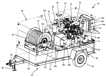
100111 Fig. 1 is a partially transparent, perspective view of a self-
contained,
flameless heat transfer fluid heating system in accordance with the present
disclosure;
[0012] Fig. 2 is a vertical sectional view of the heating system
taken from the left
side of Fig. 1;
[0013] Fig. 3 is a vertical sectional view of the heating system
taken from the
right side of Fig. 1;
[0014] Fig. 4 is a top view of the heating system of Fig 1.;
[0015] Fig. 5 is a schematic diagram of the heating system of Fig. 1;
- 4 -
CA 02811829 2013-04-04
[0016] Fig. 6 is a perspective view of an internal combustion engine
and shell
and tube heat exchanger used in the heating system;
[0017] Figs. 7A and 7B are perspective views of a reservoir used in
the heating
system;
[0018] Fig. 8 is a perspective view of a pump used in the heating
system;
[0019] Fig. 9 is a perspective view of the shell and tube heat
exchanger used in
the heating system;
[0020] Fig. 10 is a perspective view of a heat generator used in the
heating
system;
[0021] Fig. 11 is an isolated perspective view of a rotor and shaft
used in the heat
generator at Fig. 10;
[0022] Fig. 12 is a perspective view of a radiator used in the
heating system;
[0023] Fig. 13 is a front view of a hose reel used in the heating
system;
[0024] Fig. 14 is a left-side perspective view of the heating system
similar to Fig.
1;
[0025] Fig. 15 is a right-side perspective view of the heating
system of Fig. 1;
and
[0026] Fig. 16 is a further right-side perspective view of the
heating system of
Fig. 1 showing a number of access doors in an open position.
DETAILED DESCRIPTION
[0027] Referring now to Figs. 1-5, thereshown is an embodiment of a
self-
contained, flameless heat transfer fluid heating system 10 in accordance with
the present
disclosure. In the embodiment shown in the drawings, the heating system 10 is
a mobile trailer-
based heater that circulates and heats a supply of heat transfer fluid in a
closed loop. In an
exemplary application, the heating system 10 is designed for cold weather use
in thawing frozen
ground and other surfaces or for concrete curing, or to supply temporary
heated air, such as on
construction sites, for disaster recovery, or drying of various objects.
[0028] The heating system 10 is generally comprised of a group of
main
operating components including an internal combustion engine 12, a heat
transfer fluid reservoir
14, a centrifugal pump 16, a fluid heat exchanger 18, a dynamic heat generator
20, a fluid to air
- 5 -
CA 02811829 2013-04-04
heat exchanger 22 and a rotatable reel 24 provided with a closed loop conduit
arrangement 26
spooled thereon. As will be further described hereafter, in this embodiment,
the main operating
components of the heating system 10 are protectively housed and variously
supported on a main
deck 28 or surrounding wall structure 30 defining an enclosure mounted on a
mobile unit in the
form of a trailer 32 designed to be transported by a towing vehicle. The
trailer 32 has a
framework 34 provided with a set of ground engaging wheels 36 and a hitching
apparatus 38
including at least one supporting jack 40. It should be understood that the
trailer 32 may suitably
be replaced by a self-propelled mobile vehicle housing the main operating
components of the
heating system 10, and that the mobile unit may take other configuration to
allow the heating
system 10 to be transported.
[0029] In the description to follow, Figs. 1-4 illustrate the
physical relationship
and proximity of the main operating components. Fig. 5 depicts the schematic
interconnection of
the main operating components. Figs. 6-13 show isolated views of the main
components, and
Figs. 14-16 reveal details of the mobile mounting of the heating system 10.
[0030] The internal combustion engine 12 drives the heating system
10 and is
preferably embodied in a diesel engine, such as represented in the isolated
view of Fig. 6. The
diesel engine 12 is suitably supported on the main deck 28 of the trailer 32,
and is constructed
with typical components that are necessary to facilitate prime mover
operation. These engine
components include an engine block 42 having a driven rotatable crankshaft, a
crankshaft pulley
44, a flywheel 46, an alternator 48, an air intake assembly 50, an air cleaner
52, a turbo 54 and an
exhaust pipe 56. With reference to Fig. 2, the exhaust pipe 56 is routed
through an exhaust heat
exchanger 58 mounted on the main deck 28, and connected to a muffler 60 having
an exhaust
outlet 62 so that exhaust gas from engine 12 is discharged outside the top of
enclosure 30. The
outlet 62 is covered with a protective movable rain cap 63 that normally
permits the opening of
the outlet 62 in the presence of exhaust gas flow, and closes to prevent entry
of precipitation and
other foreign items when there is no exhaust gas flow. The internal combustion
engine 12
operates at high temperatures and thus requires continuous or intermittent
cooling during
operation to prevent thermal breakdown and to increase efficiency.
Accordingly, as is well
known, the engine 12 also typically includes a water jacket having an inlet
and an outlet to allow
engine coolant, such as a liquid antifreeze and water solution, to be pumped
therethrough. As
- 6 -
CA 02811829 2013-04-04
will be further explained below, the water jacket is operably connected to the
heat exchanger 18.
An electrical source for actuating the engine 12 and providing auxiliary power
is provided by a
set of batteries 64 mounted on the trailer main deck 28 as seen best in Figs.
2 and 4. Other well-
known engine related components such as filters, pumps, pulleys, and belts are
not specifically
identified in Fig. 6, but the scope and content of these components are known
to one skilled in
the art. It should be understood that other internal combustion engines may be
used for powering
the heating system 10.
[0031] The heat transfer fluid reservoir 14 is mounted on the trailer
main deck 28
at a rearward end thereof, and is constructed to hold a supply of heat
transfer fluid, such as
propylene glycol liquid, at an ambient temperature. As seen best in Figs. 7A
and 7B, the
reservoir 14 has a top wall that includes a fill port 66 that is normally held
closed by a pressure
cap 68 (Fig. 1) vented into the enclosure 30 as represented by a conduit 69
(Fig. 5). The
reservoir 14 also includes side wall structure provided with a vent port 70,
sight glass ports 72 for
monitoring the level of glycol within the reservoir 14, a supply outlet 74 in
fluid communication
with the pump 16, and a return inlet 76 in fluid communication with the fluid
to air heat
exchanger 22 and the hose reel 24 with its conduit arrangement 26. In
addition, the reservoir 14
is provided with a drain valve 78 as shown in Fig. 5.
[0032] The pump 16 is supported adjacent the engine 12 and, as seen
in Fig. 8,
has one end formed with an inlet 80 that is interconnected by a conduit
represented at 82 (Fig. 5)
with the supply outlet 74 of the reservoir 14. A top portion of the pump 16 is
designed with an
outlet 84 in fluid communication with the fluid heat exchanger 18. The pump 16
also has a
rotatable shaft 86 opposite inlet 80 that carries a pulley 88 (Fig. 2) that is
belt driven by the
engine 12 to move pressurized heat transfer fluid, such as glycol, from the
reservoir 14 through
the outlet 84 to the heat exchanger 18 and the remainder of system 10.
[0033] The fluid heat exchanger 18 is mounted on a bracket supported
from the
trailer enclosure 30, and, in the depicted embodiment, takes the form of a
shell and tube heat
exchanger in fluid communication with both the internal combustion engine 12
and the pump 16.
As best represented in Fig. 9, the heat exchanger 18 has a first shell 90
designed to hold engine
coolant therein and to function as an expansion tank. The first shell 90 is
constructed with a fill
port 92 that is normally closed by a vented pressure cap 94. The heat
exchanger 18 has a second
- 7 -
CA 02811829 2013-04-04
shell 96 joined and in fluid communication with the first shell 90, and having
a heat transfer fluid
inlet 97, a heat transfer fluid outlet 98, an engine coolant inlet 100 and an
engine coolant outlet
102. The heat transfer fluid inlet 97 is interconnected by a conduit
represented at 104 (Fig. 5)
with the pump outlet 84, and the heat transfer fluid outlet 98 is in fluid
communication with the
dynamic heat generator 20. The engine coolant inlet 100 and outlet 102 of the
heat exchanger 18
are interconnected by a conduit arrangement 106, 107 with the outlet and
inlet, respectively, of
the engine water jacket in which the engine coolant is normally heated by
operation of the engine
12.
[0034] As is well known with shell and tube heat exchangers, the
interior of
second shell 96 contains a tubular structure through which the heat transfer
fluid at ambient
temperature flows. The heated engine coolant from the engine water jacket
interfaces or flows in
the shell 96 around the tubular structure carrying the heated engine coolant
so that heat is
exchanged between the heated engine coolant and the heat transfer fluid at
ambient temperature.
The first shell 90 provides an area within which the heated engine coolant can
expand as the
system cycles thermally in order to prevent thermal deformation of the heat
exchanger 18. As a
result, the heat exchanger 18 functions to transfer heat from the heated
engine coolant to the heat
transfer fluid at ambient temperature so that a supply of initially heated
transfer fluid is delivered
to the heat generator 20. At the same time, cooled engine coolant is returned
to the water jacket
of the engine 12. Because the heat transfer fluid is heated and the engine
coolant cooled, the heat
exchanger 18 may be described as a dual fluid heat exchanger.
[0035] Referring to Figs. 2, 3 and 10, the dynamic heat generator 20
is a
mechanically driven fluid heater which uses rotary shaft input to
instantaneously and directly
heat fluids received within the heat generator without a heat exchanger. In
the exemplary
embodiment, the heat generator 20 is a commercially available product supplied
by Island City,
LLC of Merrill, Wisconsin. The dynamic heat generator 20 includes a mounting
plate assembly
108 which is coupled to the rotatable flywheel 46 of the engine 12 so as to
rotate an inlet end 110
of a drive shaft 112 associated with the mounting plate 108. An outlet end 114
of the rotatable
drive shaft 112 carries a belt and pulley arrangement 116 which transfers
rotation to a pulley
fixed on an end of a shaft 118 that mounts a fan 119 (Fig. 3) within a blower
arrangement 120.
The heat generator 20 has an inlet 122 that is interconnected by means of a
conduit represented at
- 8 -
CA 02811829 2013-04-04
124 (Fig. 5) with the heat transfer outlet 98 of the heat exchanger 18. The
heat generator 20
further has an outlet 126 that is in fluid communication with a three-way
valve 128 by means of
a conduit represented at 130 in Fig. 5.
100361 Heated transfer fluid, such as glycol, supplied by heat
exchanger 18 to the
inlet 122 is mechanically driven by a rotor 131 (Fig. 11) mounted on the drive
shaft 112 inside a
housing of the heat generator 20. This results in circulation that causes
fluid friction creating
further heat in the heated transfer fluid so that the fluid temperature of the
glycol increases to
about 215 F. As depicted in the schematic of Fig. 5, a drain valve 132 is
provided for emptying
the heat generator 20, and a leak off conduit represented at 134 receives
amounts of any heated
transfer fluid which may leak past internal seals and bearings of the heat
generator 20 in the
event of failure of those bearings and seals. Any leak off fluid is then
returned via conduit 134 to
the reservoir 14.
[0037] With further reference to Fig. 5, the three-way valve 128 at
the outlet 126
of the heat generator 20 defines a control arrangement for selectively
regulating the flow of
heated transfer fluid through the system 10. The valve 128 is in fluid
communication with the
fluid to air heat exchanger 22. In the example shown, the heat exchanger 22
takes the form of a
liquid to air heat exchanger, such as a radiator, that may be mounted at the
rear of the trailer
enclosure 30. As seen in Fig. 12, the radiator 22 includes an inlet 136 in
fluid communication
with valve 128 by means of a conduit represented at 138 in Fig. 5. An outlet
140 on the radiator
22 is in fluid communication with the reservoir 14 by means of a conduit
represented at 142. A
vent port 144 is provided at the top of the radiator 22, and a drain port 146
provided on the
bottom thereof
[0038] The valve 128 is also in fluid communication with the hose
reel 24 by
means of a conduit represented at 148 in Fig. 5. Conduit 148 is provided with
a temperature
sensor 149 for monitoring the temperature of the heated glycol being sent from
the heat
generator 20. The hose reel 24 is rotatably mounted on a support structure 150
provided on the
main deck 28 at a front end of the trailer 32. The hose reel 24 carries the
closed loop conduit
arrangement 26, and may be driven, for example by a motor 152 and intermeshing
gear
arrangement 154 seen in Figs. 1 and 2, to automatically extend and retract the
conduit
arrangement 26 relative to the hose reel 24. Although not shown, a crank or
handle may be
- 9 -
CA 02811829 2013-04-04
provided on hose reel 24 for manually controlling winding and unwinding of the
conduit
arrangement 26. As seen in Fig. 13, the hose reel 24 includes a fluid inlet
156 in fluid
communication with the valve 128 by means of the conduit 148. Fluid inlet 156
is in fluid
communication with a supply port 158 on the hose reel 24 as well as an inlet
to the closed loop
conduit arrangement 26. An outlet of the closed loop conduit arrangement 26 is
in fluid
communication with a return port 160 and a fluid outlet 162 on the hose reel
24. The fluid outlet
162 is in fluid communication with the reservoir 14 by means of a return
conduit represented in
Fig. 5 at 164.
[0039] Referring now Figs. 14-16, the aforedescribed main operating
components 12, 14, 16, 18, 20, 22, 24 and 26 of the heating system 10 are
located within the
surrounding trailer enclosure 30 defined by a front wall 166, a left side wall
168, a right side wall
170, a rear wall 172 and a top wall 174. An understructure 176 is provided
beneath the main
deck 28 for storing equipment, tools and the like as well as housing a fuel
tank for the engine 12.
[0040] The enclosure 30 includes a number of access and service
doors which
are movable between closed positions and open positions. More specifically,
front wall 166
includes an access door 178 that can be opened to access the hose reel 24 and
conduit
arrangement 26. Left side wall 168 includes a pair of service doors 180, 182
for servicing the
interior of the enclosure from the left side and rear portion thereof. Left
side wall 168 also
includes an air outlet 184 in communication with an external cylindrical duct
186 to which a
suitably sized air hose may be removably attached. The air outlet 184 is also
in communication
with the blower arrangement 120, the exhaust heat exchanger 58 and an air duct
185 (Figs. 1 and
4) located between the exhaust heat exchanger 58 and the air outlet 184. Right
side wall 170
includes a pair of service doors 186, 188 for servicing the interior of the
enclosure 30 from the
right side and rear portion thereof. Service door 186 is provided with an
access door 190 for
accessing a control panel 192 (Fig. 15) mounted in the enclosure 30. Rear wall
172 includes a
framework 194 housing a series of louvers 196 (Fig. 1) in alignment with an
air opening 198
which is in communication with the radiator 22. The framework 194 has a handle
199 for
controlling opening and closing of the louvers 196. The top wall 174 is formed
with openings
through which the upper ends of the air intake assembly 50 and the exhaust
outlet 62 project.
Top wall 174 is also provided with a series of lift elements 200 which are
engageable with a
-10-.
CA 02811829 2013-04-04
lifting device, such as a crane hook, should be desirable to transport the
system 10 other than by
towing the wheeled trailer enclosure 30 with a vehicle. As seen in Fig. 16,
the understructure
176 is provided with a service door 202 for accessing a storage compartment
204.
100411 In use, the heating system 10 is placed at a desired location,
engine 12 is
started and control panel 192 is actuated so that the pump 16 will deliver
heat transfer fluid, such
as glycol, from reservoir 14 to the heat exchanger 18. The heat exchanger 18
removes heat from
the heated engine coolant supplied from the engine water jacket, and transfers
that heat to the
heat transfer fluid while simultaneously enabling return of cooled engine
coolant back to the
water jacket. The heated transfer fluid continues to be pumped to the engine-
driven heat
generator 20 where it is further heated due to the fluid friction created by
the rotor 131 inside the
heat generator 20 as it circulates the heated transfer fluid therein.
100421 Should it be desired, for example, to thaw frozen ground or
another
frozen surface or object, such as a frozen pipe, or if it is desired to cure
concrete in a cold
environment in a ground loop mode, the closed loop conduit arrangement 26 is
unspooled from
the hose arrangement 24, and positioned over or under a surface or object to
be thawed or cured,
as desired. Valve 128 on heat generator 20 is then operated to transfer and
circulate heated
transfer fluid by means of pump 16 through the conduit arrangement 26 such
that heat from the
heated transfer fluid therein is radiated to the desired targeted cold
environment. During this
process, heat is removed from the heated transfer fluid and returned to the
reservoir 14 so that the
transfer fluid can again be heated.
[0043] Should it be desired to provide a temporary source of heated
air in an air
heat mode, the valve 128 is operated to transfer heated transfer fluid to the
radiator 22 so that it
radiates the heat from the heated transfer fluid to the air. The heated
transfer fluid running
through the radiator 22 is cooled and is returned to the reservoir 14. The fan
of the blower
arrangement 120 pulls the heated air from the radiator 22 across the engine 12
through the air
opening 198 and the control louvers 196 at the rear of enclosure 30 along with
radiant heat from
the engine 12 and the exhaust pipe 56 to the housing of the blower arrangement
120. The heated
air is then transferred through the exhaust heat exchanger 58 which further
captures radiant heat
from the exhaust pipe 56, and the air is further transferred through the air
duct 185 and air outlet
-11-
CA 02811829 2014-06-05
184 into the external duct 186 for use as desired. Exhaust gases from the
exhaust pipe 56 are
safely directed from the exhaust outlet 62 outside the enclosure 30.
[0044] hi some applications, the valve 128 is operated to deliver
heated transfer
fluid to both the radiator 22 and the conduit arrangement 26.
[0045] Accordingly, the present disclosure thus provides a self-
contained mobile
heating system which employs a series of heat exchangers and a heat generator
to provide a
heated closed loop conduit arrangement and/or a temporary source of heated air
with high
efficiency. Because of the flameless design of the heating system, the heat
produced has little to
no moisture making it ideal for different applications of heating areas, such
as building
construction, well sites, curing concrete, infestation control, drying flooded
buildings, or drying
agricultural products. No smelly or dangerous noxious fumes or exhaust gases
are allowed into
the heated air stream produced making the heating system safe and
environmentally acceptable.
[0046] In the foregoing description, certain terms have been used for brevity,
clarity, and
understanding. No necessary limitations are to be implied therefrom beyond the
requirements of
the prior art and/or the plain meaning of the language or terms used because
such language
and/or terms are used for descriptive purposes only and are not intended to be
broadly construed.
The systems, apparatuses, and method described herein may be used alone or in
combination
with other systems, apparatuses, and/or methods. Various equivalents,
alternatives, and
modifications are possible within the scope of the invention as described
herein.
[0047] As will be recognized by one of skill in the art, the present
application can be
utilized for many heat transfer fluids. While the detailed description
discusses use of propylene
glycol liquid, it must be recognized that other heat transfer fluids may be
transported by the
disclosed apparatus and materials as recognized in the art, including, but not
limited to: air,
water, glycol-water mixtures, ethylene glycol, synthetic hydrocarbons, paraffm
hydrocarbons,
refined mineral oils, methyl alcohol, or silicones.
- 12 -