Note: Descriptions are shown in the official language in which they were submitted.
CA 02812090 2013-03-12
WO 2012/037184 PCT/US2011/051494
MIXING DEVICE
CROSS REFERENCE TO RELATED APPLICATIONS
[0001] This application claims the benefit of priority of U.S.
Provisional
Application 61/383,272 filed September 15, 2010 and incorporated herein by
reference in
its entirety.
BACKGROUND
[0003] The present invention generally relates to a mixing device vessel
for
preparing mixed concoctions, such as cocktail beverages.
[0004] Concoctions can be prepared in a multitude of fashions. In a
cocktail
beverage, various culinary fruits and vegetables or an extraction of their
constituent parts
can be added as an ingredient along with alcohol to form a concoction having a
unique
flavor. Extractions of the constituent parts may include: solids, such as the
rind; semi-
solids, such as the pulp; liquids, extracted from the pulp; or essence,
extracted from the
rind. Combining these or other ingredients to prepare the concoction may
involve a
shaker, wherein the ingredients are combined into a tall vessel onto which a
lid is placed.
The closed vessel is shaken to thoroughly mix the ingredients and the
concoction served.
[0005] Various "shakers" exist in the art. U.S. Patent 2,030,834 to
Cominsky
describes a shaker for cocktails and other liquid refreshments, comprising a
shaker body of
vitreous or other fragile material, said shaker body being provided with
locking means
adjacent its mouth, and closure means for the mouth of the shaker body, said
closure
means including a cap member of vitreous or other fragile material fitting
within and
around the top of said shaker body, said closure means further including a
casing member
displacingly enclosing said cap member, resilient means interposed between
said cap
member and said casing member and locking means carried by said closure means
cooperating with said locking means of said shaker body, said locking means
carried by
said closure means including peripherally spaced elements respectively
cooperating with
said locking means of the shaker body and loosely engaging said cap member
peripherally
1
CA 02812090 2013-03-12
WO 2012/037184 PCT/US2011/051494
and at its lower edge, whereby the cap member and its interposed resilient
means are
retained as a unit within the casing member of the closure means upon removal
of the
closure means from the shaker body.
[0006] U.S. Patent 6,913,165 to Linz et al. describes a cocktail shaker
which has a
head adapted for releasably sealing an insulated container, having at least
one plastic wall,
where the container may be used as a drinking vessel. The shaker comprises a
shaker top
consisting of a dome portion, the dome portion having an opening at one end
for pouring
mixed drinks from the shaker, and a separate cylindrical portion secured to
said dome
portion remote from said one end opening, said cylindrical portion having a
stepped
portion for receiving said dome portion thereover and a channel on the
periphery of said
cylindrical portion; and a container for receiving drink materials for mixing,
said container
consisting of spaced apart insulating wails, and a smooth circumferential lip
bridging and
securing said walls together; and a sealing gasket seated in said peripheral
channel, said
sealing gasket having flexible ribs extending from said channel adaptable to
removably
seal said cylindrical portion within said container when said top is installed
within said
container.
[0007] U.S. Patent 7,571,830 to Lin describes a beverage shaker
consisting of an
insulated container which is configured to hold the ingredients for protein
supplement
drinks, permitting manual mixing by shaking to and fro and retains any large
pieces of the
remaining ice with the container. The shaker has a removable top member that
is attached
to the container which includes a smooth peripheral lip surrounding the
container suitable
for drinking. A strainer is supported internally by the top member and is
configured for
holding back large sized pieces of ice. A lid internally interfaces with the
top member in a
leak proof manner permitting protein supplement drink ingredients to be mixed
and
consumed directly from the shaker when the lid is removed.
[0008] U.S. Patent Application Publication 2009/0120932 to McLaughlin
describes drink ingredients being placed in a mixing container, wherein a cap
is placed on
top of the mixing container. The cap comprises a closed end connected with an
annular
open end by a surface, and has a perimeter located at the junction between the
annulus and
2
CA 02812090 2013-03-12
WO 2012/037184 PCT/US2011/051494
the surface. The annular open end contains perforations formed by holes or
fingers that fit
inside the rim of the mixing container, with the rim of the mixing container
in continuous
contact with the perimeter. The drink is poured and filtered by slightly
lifting and tilting
the cap to allow gravity to pull the liquid through the perforations, thereby
filtering the
drink and eliminating the need for a separate filter.
[0009] There is currently no device having impinging protrusions for
preparing a
mixed beverage, wherein the protrusions are within the confines of the
beverage
containing space of the container and capable of extracting portions of an
additive, such as
fruit pulp or essence to a liquid collocated in the container. To aide in the
reduction of the
number of devices needed for preparing mixed concoctions, such as beverages
and the
like, there exists a need to more simply extract portions of additive
ingredients overcoming
all the shortcomings of current devices used to prepare a mixed concoction.
SUMMARY OF THE INVENTION
[0011] The present invention generally relates to mixing device vessels
for mixing
solids and liquids to form a liquid preparation. Such vessels are useful for
preparing
beverages, such as cocktail beverages. Although the following embodiments
describe an
exemplar mixing device for the preparation of a cocktail beverage, the various
embodiments herein can also be used for the preparation of pharmaceutical
products, other
food concoctions or preparations involving mixing of solids or portions
thereof with
liquids.
[0012] With respect to cocktail beverages, solids, such as fruit, can be
a added to a
preparation to impart additional flavors or to enhance the taste. Generally,
although not
exclusively, portions of one or more fruit solids, liquid extracted from the
fruit(s) or the
essence of the fruit(s) can be combined with one or more liquids to accomplish
the taste
enhancement. In various embodiments herein, the solid(s) are placed in the
lower portion
of the vessel, over which liquids may be added. The vessel, having an upper
portion and a
lower portion, the upper portion acting as a lid, cap or plug, mateably seals
with the lower
portion and the container shaken, thereby, disturbing and distributing the
contents of the
container causing the contents to be broken down into smaller portions, the
liquids
3
CA 02812090 2013-03-12
WO 2012/037184 PCT/US2011/051494
extracted, or the essence obtained and transferred into the liquid. Additional
liquids can be
added to the preparation and the contents can be strained into a consumption
receiver, such
as a cup or glass. Straining the contents may be performed by separating the
upper and
lower portions to reveal a variable opening from which the liquids can be
dispense while
retaining the solids in the vessel.
[0013] It is an object of the present invention to provide a novel vessel
having
internal protrusions unto which added solids may impinge during shaking,
thereby
releasing portions of the solid for combining with a liquid preparation, or
the liquid or
essences derived from the impingement of the fluids and/or solids are
suitable, or
substantially mixed to the consumer's taste.
[0014] In one embodiment the vessel has an upper portion (cap) and lower
portion
(container). The cap and container may be nearly equal in size, or
sufficiently different.
The cap and container may be generally cylindrical in nature with rounded
edges, but other
shapes can be used, such as a modified or substantially conical shape. The cap
and
container may have a defined surface opposite their respective rims such that
each may rest
upright on a level surface with the cavity facing up. The cap, having a
smaller diameter
rim than the container, fits into the container, such that the cap rim and
outer surface
proximal to said rim seal around the container wall inner surface preventing
the contents
from escaping and enclosing a volume nearly the union of the two separate
volumes.
[0015] In an alternative embodiment, the cap may fit over the container.
The
container, having a smaller diameter rim than the cap, fits into the cap, such
that the
container rim and outer surface proximal to said rim seal around the cap wall
inner surface
preventing the contents from escaping.
[0016] Material for the shaker can be of various common materials such as
metal,
plastics, glass, and the like, or more exotic materials. Metal may be formed
by processes
such as casting, milling, pressing or spin forming. Plastic can be cast,
injection molded,
spun molded or milled, and glass can be formed by casting, blowing and various
other
methods.
4
CA 02812090 2013-03-12
WO 2012/037184 PCT/US2011/051494
[0017]
Further to the present embodiment, the container may be formed having an
internal protrusion of the bottom surface extending into the volume defined by
the inner
walls and the rim, and occupying a portion of the volume.
[0018] In one
embodiment there exist a mixing device comprising a seperable
upper portion having a closed end connected to an annular opening by a conical
to nearly
cylindrical side surface defining a cavity; a lower portion having a closed
end connected to
an annular opening by a conical to nearly cylindrical side surface defining a
cavity and
configured to mateably seal to said upper portion generally about their
annular openings,
said lower portion comprising a substantially large protrusion extending from
said closed
end into said lower portion cavity and operatively configured to impinge one
or more
ingredients added thereto. The device may further comprise an ingredient
facing surface
having a plurality of protrusions dispersed within the cavity and may have the
protrusion
as an insert. The device may also have the protrusions and the plurality of
protrusions
formed as or on an insert and the device may have the upper portion comprising
a
protrusion extending from said closed end into said cavity. The device may
also have the
upper portion protrusion and lower portion protrusion operatively configured
to mutually
impinge one or more ingredients when the upper portion and lower portion are
joined. The
device may alternatively have a lower portion having a grip surround axially
about the
outer surface extending from proximal to the annular opening of the lower
portion to the
mid- section.
[0019] In
another embodiment there is a method of preparing a concoction in a
mixing device comprising adding ingredients to a lower portion of said mixing
device,
said lower portion having one or more protrusions; joining a mating upper
portion
operatively forming a seal with said lower portion; shaking said
mixing device,
impinging one or more of said ingredients on said one or more protrusions; and
imparting
said at least a portion of said one or more of said ingredients into said
concoction.
[0020] In
another embodiment there exists a mixing device comprising a seperable
lower portion comprising a closed end connected to a rimmed opening by a
conical to
nearly cylindrical side surface defining a cavity, said lower portion
comprising a protrusion
CA 02812090 2013-03-12
WO 2012/037184 PCT/US2011/051494
extending from said closed end into said lower portion cavity; an upper
portion comprising
a closed end connected to a rimmed opening by a contoured conical side surface
defining a
cavity and configured to mateably seal with said rimmed opening of said lower
portion,
said upper portion side surface extending distal to said closed end, beyond
whereabout said
upper and lower portions mateably seal, and having a side surface interior
diameter
minimally larger than said lower portion rimmed opening. The device may
further
comprise an ingredient facing surface comprising a plurality of generally
small protrusions
dispersed within each cavity. The device may also have said plurality of
generally small
protrusions formed by an insert, inserted or formed into each cavity. The
device may
optionally be a beverage mixing device. The exterior surface of the upper
portion closed
end of the device may optional be relatively flat and the rim height relative
to said a closed
end may vary in a periodic manner about the circumference.
[0021] Further to the above present embodiment, the mixing device upper
portion
may comprise a sealing member affixed to the interior surface of the upper
portion and
configured in size to mate with said rim of said lower portion. The device rim
of the lower
portion may optionally seal against the inner surface of the upper portion, or
comprise a
molded hand grip incorporated into said upper or lower portion. The device may
optionally provide that the rim of the lower portion seals against the edge of
the insert of
the upper portion if the upper portion makes use of such an insert as
described. The device
as described with a varied and periodic rim height may have the rim height as
substantially
sinusoidal relative to the closed end of the upper portion.
[0022] The embodiment currently described may also exhibit an upper
portion
having a midsection with molded-in features substantially similar to that of
the varied rim,
or where a partially separated upper and lower portions reveal a geometric
shape, such as a
generally triangulated opening, from which the liquid portion of a prepared
beverage is
dispensed.
BRIEF DESCRIPTION OF THE DRAWINGS
[0023] Fig. 1 is a pictorial depiction of a mixing device vessel lower
portion
having a grip surround.
6
CA 02812090 2013-03-12
WO 2012/037184 PCT/US2011/051494
[0024] Fig. 2 is a pictorial depiction of a mixing device vessel having
an upper and
lower portion which fit together forming a seal to contain ingredients during
shaking and
preparation of a mixed concoction and further having a surface of regular
protrusions
formed by an insert in the lower portion.
[0025] Fig. 3 is a further cut-away pictorial depiction of a mixing
device vessel
having an upper and lower portion which fit together forming a seal to contain
ingredients
during shaking and preparation of a mixed concoction and further having
respective inserts
in the upper and lower portions, the lower portion also having a central
protrusion in the
concoction cavity formed by the insert.
[0026] Fig. 4 is a front perspective pictorial depiction of a mixing
device vessel
having a separated upper and lower portion which fit together forming a seal
to contain
ingredients during shaking and preparation of a mixed concoction and further
having a
molded exterior.
[0027] Fig. 5 is a front view pictorial depiction of a mixing device
vessel having a
separated upper and lower portion which fit together forming a seal to contain
ingredients
during shaking and preparation of a mixed concoction and further having a
molded
exterior.
[0028] Fig. 6 is a side view pictorial depiction of a mixing device
vessel having a
mated upper and lower portion which fit together forming a seal to contain
ingredients
during shaking and preparation of a mixed concoction and further having a
molded
exterior.
[0029] Fig. 7 is a front view pictorial depiction of a mixing device
vessel having a
mated upper and lower portion which fit together forming a seal to contain
ingredients
during shaking and preparation of a mixed concoction and further having a
molded
exterior.
[0030] Fig. 8 is a top view pictorial depiction of a mixing device vessel
lower
portion having a centrally located, substantially large, protrusion extending
from the closed
7
CA 02812090 2013-03-12
WO 2012/037184 PCT/US2011/051494
end of the cavity and further having an ingredient facing surface comprising a
plurality of
generally small protrusions dispersed within the cavity.
[0031] Fig. 9 is a bottom view pictorial depiction of a mixing device
vessel upper
portion having an ingredient facing surface comprising a plurality of
generally small
protrusions dispersed within the cavity.
DETAILED DESCRIPTION OF THE INVENTION
[0032] Mixed concoctions often require introduction of ingredients that
may
require some form of breakdown, such as pulverizing or crushing. Pulverizing
ingredients,
such as fruits for use in a cocktail beverages result in added time, utensils,
and space to
prepare the concoction as well as time necessary to maintain the area and
equipment used
for such purpose.
[0033] There is provided herein a device for preparing a mixed
concoction, such as
a cocktail beverage. The present device allows for quick and clean preparation
of a
concoction by extracting substances, or portions thereof, from ingredients
through their
impingement on one or more interior surface protrusions built into the shaking
vessel,
imparting flavor and/or aroma to the concoction from ingredients, such as
fruit. As will be
shown by the various embodiments, the vessel may be shaken to repeatedly
impinge one or
more ingredients on the protrusion(s) or the one or more ingredients may be
squeezed or
crushed by opposing impinging protrusions.
[0034] In one embodiment, the mixing device is a vessel having a
separable upper
cap portion that mates with a lower container portion thereby forming a
sealable internal
cavity when joined, such that contents within the vessel cavity may be shaken
to mix the
contents without loss of the contents. Both the container and cap have an open
annular
end and a closed end connected by a conical, cylindrical, or nearly conical
surface. The
open end of each container and cap is further defined by a perimeter at the
open annular
end. A seal may be formed by mating the two annular portions of the container
and cap,
forming a seal about the perimeter of the annular openings. The annular open
end of the
upper cap portion may be sufficiently small to fit within the internal
diameter of the
8
CA 02812090 2013-03-12
WO 2012/037184 PCT/US2011/051494
annular open end of the container portion, having the closed ends of the cap
and container
distil to one another, and the annular perimeter of the cap forming a seal
around the inner
perimeter of the container cavity wall proximal to the container's annular
opening.
[0035] In an alternative embodiment, the cap may fit over the container.
The
container, having a smaller diameter rim than the cap, fits into the cap, such
that the
container rim and outer surface proximal to said rim seal around the cap wall
inner surface
preventing the contents from escaping. The cap rim may extend beyond the point
or
location providing a seal, such that the joint of the two may be hidden from
view. The
inner diameter of the cap from the rim to the point of seal may be of
minimally larger
diameter than the rim of the container. The inner diameter of cap from the rim
to the point
of sealing may, in alternative embodiments, be minimally larger that the
coinciding portion
of the container such that the diameter varies accordingly. Such would be the
case if the
outer diameter of the container lessens from some maximum diameter to the rim.
[0036] The extended rim of the cap may vary in height relative to the
closed end or
relative to the location of seal, and relative to the perimeter. The variation
in rim height
may or may not be periodic, such that the shape of the edge changes in a
repeating pattern.
The pattern may be triangular or sinusoidal or some other geometric variant.
[0037] The pattern of the rim may also be substantially repeated in the
exterior
shape of other constituent parts of either the cap or the container. The cap,
for example
may exhibit features in the mid-section, or proximal thereto, resembling the
change in
height in the rim in a corresponding fashion.
[0038] The cap may have a sealing member disposed within the interior
perimeter
of the cap at a predetermined distance from the closed end or perimeter such
that effective
sealing may be accomplished. The seal may be formed into the interior
perimeter, adhered
to the interior perimeter, or insert by one of various means such as insert
molding, pressing
or the like. The seal has a generally constant annular and distal location,
such that it
coincides with the shape of the contain rim to provide a mateable seal with
the container.
It is envisioned that a sealable member might be formed within the cap to
accommodate a
container rim that is not annular or such that the seal is a constant distance
from the closed
9
CA 02812090 2013-03-12
WO 2012/037184 PCT/US2011/051494
end. A seal may be formed from rubber, silicone, plastic or some other
suitably soft
material consistent with the materials being prepared.
[0039] A mateable seal, or mateably sealing is defined as providing a
seal between
the upper portion and lower portion when mated, wherein each closed end is
distal to each
other, thus forming a combined cavity and the contents are prevented from
escaping.
[0040] The vessel may be constructed from any solid, relatively ridge
material,
such as glass, metal, plastic, composite or some other non-limiting suitable
material. The
vessel may further be constructed of a combination of materials, such as metal
with plastic
inserts and soft rubber surrounds. The cap may be constructed of the same
materials in the
same fashion as the container or be constructed in an alternative fashion,
such that the
container and cap might perform different functions. The vessel may be a
single or multi-
walled vessel. The vessel may also be constructed to have multiple layers, of
the same or
differing materials, such that each is operatively configured to serve a
different purpose in
manufacture and/or use.
[0041] In one embodiment, the closed end of the container comprises a
protrusion
extending into the vessel cavity. The protrusion may be press-formed by
depression of the
bottom, or closed end, of the container into the cavity, such as by stamping.
The
protrusion may be small, consuming little of the cavity volume, or may be
large,
consuming a considerable portion of the cavity volume. The protrusion may be
conical,
cylindrical, flat, pyramidal or any number of shapes.
[0042] In a further embodiment, the container protrusion may be added to
the
interior portion of the closed end of the container by joining pieces during
manufacturing
by means of a connection such as bonding, adhering, welding, latching or
threading (or the
like). The protrusion may also form the entirety of the closed end or be a
part, or feature,
of the piece that forms the closed end to which the annular open end is
connected by the
conical, cylindrical or nearly conical side surface.
[0043] In one embodiment, the protrusion is selectable as an insert and
may be
removed and/or replaced. The protrusion insert is installed from the interior
side and
CA 02812090 2013-03-12
WO 2012/037184 PCT/US2011/051494
locked into position to the closed end of the container by a locking ring, an
interference fit
with or without tabs, or mating feature formed in the material of the closed
end.
[0044] In an alternative embodiment, the insert may also be installed
into a through
hole in the otherwise closed end of the container distal to the annular open
end. The
protrusion insert may be inserted via the exterior side or the interior side
and suitable
sealed and locked into position so as to prevent escape of any ingredients.
Locking means
may comprise threads, twist-locks, locking rings or the like. Seals may be
formed from 0-
rings, flat washer shapes or other known means. Various insert shapes can be
made and
swapped out as replaceable inserts. Shapes may be interchanged such that a
small
protrusion may be removed in favor a larger one, or one having a shape not
substantially
conical. Shapes may be categorized and deemed best for certain functions, such
as
extracting essence, verses extracting rind.
[0045] In one embodiment, the protrusion may have further secondary
protrusions
of finer or smaller detail on the interior wall of the ingredient facing
surface. These
secondary protrusions or surface treatment may comprise pyramidal, semi-
spherical,
conical, cylindrical, or other shapes and may cover a substantial portion of
the primary
protrusion. Coverage may exist near or at the tip distal to the closed end, in
the middle or
at the bottom of the primary protrusion, proximal to the closed end and distal
to the
annular open end of the container. The secondary protrusion shapes may be
regular in
their arrangement or irregular and may be combined with various other shapes.
The
secondary protrusions may be oriented to face substantially into the vessel
cavity, reducing
it's volume, or negatively oriented, such that they might add to the volume.
[0046] Alternatively the container may be formed such that the interior,
or inner,
wall of the conical to nearly cylindrical side surface connecting the open end
with the
closed end of the container exhibits one or more secondary protrusions,
equivalent or
nearly equivalent to those described above. The side surface material may be
substantially
thick enough, such as if made from plastic to have a differing interior
surface finish than
the exterior surface. The container may again be a dual walled container such
that the
inner and outer side surfaces connecting the annular open end and the closed
end have
11
CA 02812090 2013-03-12
WO 2012/037184 PCT/US2011/051494
different surface textures. The exterior wall may be formed such that the
closed end, or
bottom, is flat to allow the container to suitably rest on a table surface
with the open end
facing upward.
[0047] The protrusions of the container may be formed by an insert
comprising the
central protrusion and the secondary protrusions. The central protrusion may
form the
bottom, or closed end of the insert and be joined to an annular opening by a
conical to
nearly cylindrical wall. The insert may be manufactured as a one piece
injection molded
part or as multiple parts combined in the container at a later time. The
insert may be
operatively configured to be insert molded into an existing container or
created to match a
known container and mated at a later time.
[0048] In one embodiment, the vessel container having a protrusion
extending into
the vessel cavity and connected to the closed end of the container is formed
having a cavity
filled with a heat transfer medium and sealed. The protrusion may have in
concert with
the filled cavity, secondary protrusions to impart the greatest rate of heat
transfer in the
given time a shaker is used to mix ingredients. The heat-transfer medium may
be used to
cool the concoction or alternatively heat the concoction. The container may be
stored in a
relatively cool or hot local until needed. As previously described the
protrusion may be a
replaceable insert and alone may be stored in a relatively cool place, such as
a freezer, or in
a relatively hot place like a warming tray or holder.
[0049] In an alternative embodiment, the protrusion may be hollow and
accessible
from an exterior part of the closed end of the vessel. A formed insert,
matching the
interior dimensions of the hollow cavity of the protrusion and containing a
heat transfer
medium may be replaceably inserted and locked into position, or removed.
Insert and
locking means may be performed and configured as previously described above
and as are
described below.
[0050] In one embodiment, the upper portion cap has an annular open end
and
closed end, the closed end having one or more protrusions across the surface
facing inward
toward the vessel cavity. The protrusions may be of various shapes comprising
pyramidal
shapes, conical shapes, semi-spherical shapes, or the like. The shapes may be
substantially
12
CA 02812090 2013-03-12
WO 2012/037184 PCT/US2011/051494
flat relative to one another or varied in their size, shape, and type. The one
or more
protrusions may be placed in a geometric pattern or dispersed in an irregular
arrangement,
or at least appear to be irregular in their arrangement.
[0051] In an alternative embodiment, the upper portion cap has a
protrusion
extending from the closed end directed inward toward the vessel cavity. The
upper cap
protrusion can extend outward proximal to an opposing protrusion extending
from the
container into the vessel cavity, such that the two protrusions are
operatively configured to
form a mutual impingement point when both portions are brought together. The
mutual
impingement point may be used to hold predetermined ingredients, such as a
piece or
portion of fruit, or crush the ingredient during the joining process. In this
way the liquid
ingredients are added and the selected ingredient to be impinged is placed on
one
protrusion and during joining of the opposing portion is held or crushed
imparting pieces
or portions of the ingredient to the others.
[0052] In one embodiment, the inner portion(s) of the vessel coming into
contact
with the ingredients to be mixed may be formed of plastic and bonded to an
intermediate
layer composed of metal, such as 18/8 stainless steel. The bond may be formed
by hot
insert molding of the plastic into the metal or formed by the use of a
suitable adhesive.
The plastic insert(s) may exhibit a central protrusion and secondary smaller
protrusions
across the ingredient contacting surface. The insert may or may not be
removable and may
be formed to be added to pre-existing mixing devices of matched shape and
combined at a
later time. The vessel may further have incorporated onto the outward surface
of the metal
intermediate layer an insulating layer, such as rubber, forming a gripping
surface and
minimizing the heat transfer between the user and the vessel.
[0053] In another embodiment the upper and lower portions may comprise
double
walls having inner and outer materials/layers, such that the two materials are
spaced apart
to create a cavity between them. The cavity can be filled with solid
insulating materials, or
evacuated and sealed to provide a vacuum chamber. The rims of the two walls
may joined
dependent on the material of use. The two walls of the lower portion may
comprise an
inner semi-cylinder and an outer semi-cylinder. The inner lower portion may
have a
13
CA 02812090 2013-03-12
WO 2012/037184 PCT/US2011/051494
plurality of protrusions extending into the cavity into which the beverage
ingredients as
previously described.
[0054] The upper portion and lower portion of the shaker can be vacuum
formed to
create an inner and outer surface distal from each other and having different
textures, such
that the interior surface is patterned. In one embodiment the inner surface is
a pyramidal
form and the outer surface is smooth or semi-smooth, such as with brushed
stainless steel.
[0055] In Fig. /, there is shown an exemplar mixing device lower
container 100
having a grip 104 surrounding the outer surface of the container extending
from proximal
to the annular opening 102 down to approximately the mid section. The grip 104
may, in
alternative arrangements, extend from nearly the annular opening 102 to the
bottom of the
surface connecting the annular opening to the closed end 108, or surround the
exterior
surface of the container 100 entirely. The grip 104 may be composed of a
rubber ring,
foam, or other suitable material or application method such as spray painting
a surface
treatment such as rubberized paint. The main body 106 may be constructed from
a
relatively rigid, yet durable material, such as metal or plastic.
[0056] Turning to Fig. 2, there is shown an exemplary mixing device
vessel 210
having an upper portion cap 212 and a lower portion container 214, each
portion have a
main body 224 and 226 respectively, and each formed with a closed end 216 and
218
respectively, connected to an open annular end 220 and 222 respectively, by a
semi-
conical, to nearly cylindrical side surface. The main bodies 224 and 226 may
be
constructed from a relatively rigid material, such as metal. The container has
an insert
234 bonded to the inner wall of the container body 224 having surface
protrusions 232
arranged in a regular pattern and composed of a regular geometric shape. The
insert
extends into the contain body cavity from proximal to the annular opening 222
down the
inner wall.
[0057] Turning to Fig. 3, there is disclosed an embodiment of a mixing
device
having one or more alternative features. The container body 324 has bonded
into its
interior cavity a plastic insert 334 extending from the closed end 318 up
along the inner
wall of the contain body 324 and terminating proximal to the open annular end
322.
14
CA 02812090 2013-03-12
WO 2012/037184 PCT/US2011/051494
Molded (or bonded) into the insert 334 at the closed end is a roughly conical
shaped
central protrusion 328 narrowing toward the open annular end 322 of the
container 314
that can be used to extract substance from an otherwise solid or semi-sold
ingredient when
the closed vessel is shaken. The ingredient facing surface of the insert 334
may have
further geometric secondary protrusions 332 molded in place in a regular or
irregular
pattern extending from the bottom, or closed end, to nearly to full height of
the insert 334,
approaching the annular opening 338 end of the insert 334. The secondary
protrusions 332
may also be incorporated into the surface of the central protrusion 328 and
may be regular
or irregular and may extend from the bottom, closed end to the tip of the
central protrusion
328 or only cover a portion of the surface.
[0058] A cavity may be formed (not shown) from the inner body of the
central
protrusion wherein a heat transfer medium may be located and sealed by capping
the
cavity or the bonding of insert 334 into the container 324 inner wall.
[0059] A sealing surface along the annular opening 338 end of the insert
334 may
be formed such that the annular opening 320 of the upper cap 312 may be seated
against
the sealing surface to form a seal, holding the contents securely into the
closed vessel
during shaking.
[0060] Further to Fig. 3, the upper cap 312, having a cap body 326
exhibits bonded
into its interior cavity an insert 342 extending from the cap closed end 316,
within the
cavity, up the cap inner wall terminating proximal to the annular opening 320.
The insert
340 has multiple surface protrusions 350 on the ingredient facing surface
extending from
the bottom to the rim, or annular opening, of the insert. The closed end, or
bottom, of the
insert 342 is raised, extending into the cap cavity and has surface
protrusions 342 that are
of mutually equal height measured from the closed end, or bottom. The surface
protrusions are of regularly shaped geometric figures and regularly spaced as
shown or
alternatively may be irregular in shape and spacing. The insert may exhibit a
central
primary protrusion similar to that described above for the container 314. An
alternative
embodiment may have no surface protrusions along the inner wall with the
insert limited
to the raised closed end.
CA 02812090 2013-03-12
WO 2012/037184 PCT/US2011/051494
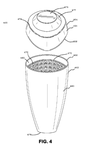
[0061] In Fig. 4, there is shown an exemplar mixing device of an
alternative
embodiment. The mixing device vessel 460 having an upper portion cap 464 and a
lower
portion container 462, each portion have a main body 484 and 480 respectively,
and each
formed with a closed end 476 and 478 respectively, connected to an open end
466 and 468
respectively, by a semi-conical, to nearly cylindrical side surface or
contoured side surface.
The main bodies 480 and 484 may be constructed from a relatively rigid
material, such as
plastic, and may have one or more surface treatments or textures. The
treatments or
textures may be distributed about each portion. The exterior portions may
exhibit a satin
finish while the internal area may be smooth or glossy. The treatment or
texture may assist
holding the device during shaking or to more easily distinguish the parts in a
dark
environment. The material may exhibit a retro reflective nature or be photo
luminescent.
The container 462 has an optional insert 470 bonded, or insert molded, to the
inner wall
482 of the container body 480; the insert having a plurality of generally
small to modest
sized surface protrusions 472 arranged in a regular pattern and composed of a
regular
geometric shape. The insert 470 extends into the container 462 cavity from
proximal to
the annular opening 466 down the inner wall and includes a closed end
(hidden). The
surface protrusions may be alternatively formed in the body materials.
[0062] Further to Fig. 4, the cap 464 and container 462 have a
substantially flat
closed end outer surface 476 and 478 respectively, with the cap further having
a sloped
feature 477 joined to a molded contour 474 generally matching that of the rim
468. The
closed end 478 of the container 462 may be narrow as shown, or broadened to
increase
stability.
[0063] Turning to Fig. 5, the same embodiment of Fig. 4 is shown in a
separated
view further illustrating the mixing device. The mixing device 460 contours of
the cap
464 exhibit a multi-conical shape joined by the conical feature 474.
Specifically, the
contour feature 74 can be seen to generally resemble that of the rim 468 on
the cap 474,
which may act as a molded grip for the user to aid in maintaining the mateable
seal of the
two portions. The constant annular rim 466 of the container 462 is evident as
is the inner
surface 482.
16
CA 02812090 2013-03-12
WO 2012/037184 PCT/US2011/051494
[0064] Fig. 6 is a side of the exemplar embodiment shown in Figs. 4-5,
where the
upper cap 464 and lower contain 462 portions are mateably sealed. The mixing
device
460, specifically the cap 464 has a varying height rim about the perimeter.
The overlap
690 of the cap 464 to the container 462 can be seen as is the contour of the
rim height 669.
The rim 466 of the container 462 is hidden from view by the extended rim 468
of the cap
464. A slight separation of the cap 464 and container 462 would review an
opening (not
shown) from which the liquid contents may be dispensed while filtering back
the solids.
In the embodiment shown, the opening would appear to have an straight side and
an
arched side coinciding with the relative heights or contour of the respective
rim perimeters.
[0065] In the embodiment shown in Fig 6, the rim height is arched in a
twice
repeated pattern around the perimeter of the cap 460, thus having a similar
appearance on
the opposing side view. Likewise the front view, as shown in Fig. 7, and rear
view are
similar. Optionally the front view may further exhibit a logo impressed into
the material
or applied by known means.
[0066] Turning to Fig. 8, an embodiment of a mixing device container 802
is
shown in a top down view. The container 802 has a centrally located and
substantially
large protrusion 808 extending from the closed end 896 and may optionally be
formed
with the closed end 896 and the plurality of generally small or modest
protrustions 804
lining the interior surface, including the centrally located substantially
large protrusion.
The internal features as described may be formed, as stated above, in an
insert which is
placed into the container 802 either before or after the container 802 is
formed. In the
figure, the plurality of generally small to modest protrusions 804 vary in
size relative to the
height in the container 802. The small to modestly sized protrusions may take
shapes
other than what is shown and may not necessarily be in an ordered fashion or
each be of
similar shape.
[0067] The protrusions shown in the figure appear to extend from the
closed end
up and proximal to the rim 806 terminating in an edge 810 that may or may not
act in a
sealing capacity. In one embodiment the insert material is formed from a hard
type plastic,
therefore the edge 810 of the insert would not suitably function as a seal.
However, the
17
CA 02812090 2013-03-12
WO 2012/037184 PCT/US2011/051494
edge may provide mechanical support for a softer and insertable seal as
previously
described, but not shown, such that the seal is adhered to the edge and/or the
inner surface
812, or formed in place during manufacture. Alternatively, the edge 810 may be
distal to
the rim 806 sufficiently to provide clearance for an interference fit of a cap
(not shown)
and the container 802, as described above.
[0068] In Fig. 9, an embodiment of a mixing device cap 920 is shown in a
bottom
up view highlighting the cap cavity. The cap 920 has a closed end 928 and the
plurality of
generally small or modest protrusions 926 lining the interior surface,
including the closed
end 928. The internal features as described may be formed, as stated above, as
an insert
which is placed into the cap 920 either before or after the cap 920 is formed.
In the figure,
the plurality of generally small to modest protrusions 926 vary in size
relative to the height
and inner diameter of in the cap 920. The small to modestly sized protrusions
926 may
take shapes other than what is shown and may not necessarily be in an ordered
fashion or
each be of similar shape.
[0069] The protrusions shown in the figure appear to extend from the
closed end
up and proximal to the rim 924 terminating in an edge 922 that may or may not
act in a
sealing capacity. In one embodiment the insert material is formed from a hard
type plastic,
therefore the edge 910 of the insert would not suitably function as a seal.
However, the
edge may provide mechanical support for a softer and insertable seal as
previously
described, but not shown, such that the seal is adhered to the edge and/or the
inner surface
930, or formed in place during manufacture. Alternatively, the edge 922 of the
insert may
be sufficiently distal to the rim 924 to provide clearance for an interference
fit of a
container, such as the container 902, shown in Fig. 8, and described above.
18
CA 02812090 2013-03-12
WO 2012/037184 PCT/US2011/051494
STATEMENT REGARDING PREFERRED EMBODIMENTS
[0070] While the invention has been described with respect to preferred
embodiments, those skilled in the art will readily appreciate that various
changes and/or
modifications can be made to the invention without departing from the spirit
or scope of
the invention as defined by the appended claims. All documents cited herein
are
incorporated by reference herein where appropriate for teachings of additional
or
alternative details, features and/or technical background.
19