Note: Descriptions are shown in the official language in which they were submitted.
CA 02812331 2013-03-27
HEAD TUBE RESET MECHANISM FOR A SCOOTER
BACKGROUND OF THE INVENTION
a) Field of the Invention
The present invention relates to a scooter, and more particularly to a
head tube reset mechanism for a scooter, with the head tube reset
mechanism being a simple structure and assembled conveniently.
b) Description of the Prior Art
A conventional scooter design with a triangular configuration and a
handle that can swing left and right to drive and move the scooter body is
shown in FIG. 1. A front end of the scooter body is provided primarily
with a head tube 11, the head tube 11 is pivoted with a stem 21 that can
rotate freely, and a front wheel 31 is connected to a lower end of the
stem 21 through a front fork 22; whereas, an upper end of the stem 21 is
installed with a handle 23. In addition, two sides of the scooter body
are provided respectively with a rod 41 that is extended backward by a
predetermined length. The two rods 41 are stretched outward by a
predetermined included angle and two rear wheels 32 are provided
respectively at a rear end of each rod 41. Therefore, a basic scooter
structure that allows for riding stably is formed.
CA 02812331 2013-03-27
For other similar conventional scooters, in addition to that the
handle 23 can be used to control the front wheel 3110 turn, by the design
that the head tube 11 can swing left and right, a user can swing the front
wheel 31 left and right at the same time when swinging the handle 23 left
and right, and can roll the scooter forward along an S-shaped route while
the front wheel 31 swings left and right, thereby achieving the effects of
exercise and entertainment when the scooter glides forward.
Moreover, to increase the smoothness when riding the scooter and
to achieve the effect of labor saving, the similar scooter is further
provided with a reset mechanism that always keeps the head tube 11 at
a central upright position. Referring to FIG. 2, under the condition that
the head tube 11 of the scooter can swing left and right, a lower end of
the head tube Ills provided forward with a trunnion 111, and front ends
of the two rods 41 are pivoted with the trunnion 111 by a bolt 12. Aside
of the head tube 11 opposite to the trunnion 111 is provided backward
with a first shaft 112 that is sheathed with a rotation block 13. Two ends
of the rotation block 13 are provided respectively with a second shaft 131
that is protruded toward the rod 41. The two rods 41 are provided
respectively with a jacket tube 411 into which the second shaft 131 is
extended. On the other hand, the jacket tube 411 of each rod 41 is
2
CA 02812331 2013-03-27
provided with an elastomer 14 that encloses the second shaft 131.
In principle, when the head tube 11 swings left or right against the
first shaft 112, a buffering and resetting effect should be gained under
the restriction of the elastomer 14. However, the abovementioned
conventional reset mechanism is complicated and tedious. Besides
that, the elastomers 14 should be disposed between the second shafts
131 at the two sides of the rotation block 13 and the jacket tubes 411 of
the two rods 41, which not only requires higher production cost and
maintenance fees, but wastes more time and labor when assembling.
SUMMARY OF THE INVENTION
Accordingly, the present invention provides a head tube reset
mechanism for a scooter, with the head tube reset mechanism being a
simple structure and assembled conveniently.
To achieve this, the head tube reset mechanism for a scooter,
according to the present invention, is provided with a connector for
installing rear wheels, and a head tube for installing a front wheel and a
handle. A front end of the connector is provided with a jacket tube and
a filling slot that keeps a predetermined spacing from the jacket tube.
The head tube is installed at the front end of the connector and is
provided with a pivot for sheathing into the jacket tube, and a limiting unit
3
CA 02812331 2013-03-27
that is extended into the filling slot. Additionally, at least an elastomer is
installed between the filling slot of the connector and the limiting unit of
the head tube.
By the abovementioned characteristics of structures, when using
the head tube reset mechanism for a scooter, according to the present
invention, the handle and the front wheel that are installed on the head
tube can swing left and right along with the head tube against the pivot,
thereby achieving the effects of exercise and entertainment while gliding
the scooter forward. Furthermore,
under the functions of the
elastomers and the limiting unit, a buffering effect is formed to the head
tube and a resetting force is provided constantly to keep the head tube at
a central upright position, allowing the scooter to glide more smoothly
without wasting too much labor.
By the abovementioned characteristics of structures, the described
connector is formed by welding a stamping panel with the jacket tube,
and the filling slot is disposed between the jacket tube and the stamping
panel.
The abovementioned jacket tube is sheathed with at least a sliding
sleeve.
By the abovementioned characteristics of structures, two sides of
4
CA 02812331 2013-03-27
the described connector are extended backward and outward in a
diagonal direction and two side walls of the connector are provided
respectively with a predetermined number of filling holes.
By the abovementioned characteristics of structures, the described
limiting unit is constructed by two panels that are fixed on the head tube.
Ends of the two panels opposite to the head tube are engaged together
to form a plate with structural intensity; whereas, ends of the two panels
facing the head tube are folded into a joint part that is engaged with the
head tube.
In the abovementioned head tube reset mechanism for a scooter, an
elastomer is installed between the filling slot of the connector and the
limiting unit of the head tube. The elastomer is installed in the filling slot
of the connector, and a front end of the elastomer is formed with an
interference part for insertion with the limiting unit of the head tube.
The abovementioned elastomer can be a square block or a cylinder.
In the described head tube reset mechanism for a scooter, two
elastomers are installed between the filling slot of the connector and the
limiting unit of the head tube. The two elastomers are disposed
respectively at two sides of the limiting unit of the head tube, so as to be
installed in the filling slot of the connector.
5
CA 02812331 2013-03-27
The abovementioned two elastomers are a block of elastomer,
respectively.
The abovementioned two elastomers are a spring, respectively.
By the abovementioned characteristics of structures, in the
described head tube reset mechanism for a scooter, an elastomer is
installed between the filling slot of the connector and the limiting unit of
the head tube. The limiting unit is constructed by a slot-shaped panel
that is fixed on the head tube, and an end of the limiting unit opposite to
the head tube is formed with an opening. The elastomer is disposed in
the limiting unit and the connector is protruded at the filling slot with a
plate unit that is extended into the limiting unit. An end of the elastomer
facing the connector is provided with an interference part for insertion
with the plate unit.
The abovementioned elastomer can be a square block.
By the abovementioned characteristics of structures, in the head
tube reset mechanism for a scooter, two elastomers are installed
between the filling slot of the connector and the limiting unit of the head
tube. The limiting unit is constructed by a slot-shaped panel that is
fixed on the head tube, and an end of the limiting unit opposite to the
head tube is formed with an opening. The connector is protruded at the
6
CA 02812331 2013-03-27
filling slot with a plate unit that is extended into the limiting unit. The
two elastomers are disposed respectively at two sides of the plate unit of
the head tube, so as to be installed in the limiting unit.
The abovementioned two elastomers are a block of elastomer,
respectively.
The abovementioned two elastomers are a spring, respectively.
By the abovementioned characteristics of structures, in the head
tube reset mechanism for a scooter, an elastomer is installed between
the filling slot of the connector and the limiting unit of the head tube.
The filling slot of the connector is a round hole and the elastomer is an
elastic cylinder that is installed in the filling slot. The elastomer is
provided with an interference part for insertion with the limiting unit of the
head tube. The limiting unit is a rod-shaped unit that is fixed on the
head tube, and the interference part of the elastomer is a round hole.
By the abovementioned characteristics of structures, the described
head tube is provided with an end cap at a tail end of the pivot to prevent
the pivot from escaping out.
By the abovementioned characteristics of structures, the two sides
of the described connector are installed respectively with a rod member,
and a tail end of each rod member is installed with a rear wheel.
7
CA 02812331 2014-10-24
8
At least an elastic restoration element is disposed between the
abovementioned each rod member and the connector.
By the abovementioned characteristics of structures, the described head tube
is provided with a stem that can rotate freely. An upper end of the stem is
installed
with a handle; whereas, a lower end of the stem is installed with a front fork
and a
front wheel.
Specifically, the head tube reset mechanism for a scooter, according to the
present invention, is provided with following effects:
1. The parts are simple, which reduces material and assembly costs relatively.
2. The parts are simple, which reduces maintenance fees relatively.
3. The entire head tube reset mechanism for a scooter includes the connector
that is installed with the rear wheels, and the head tube that is installed
with
the front wheel and the handle, which facilitates the modularized design for
the scooter.
According to an aspect of the invention, there is provided a head tube reset
mechanism for a scooter, comprising a connector for installing rear wheels,
and a
head tube for installing a front wheel and a handle, wherein a front end of
the
connector is provided with a jacket tube and a filling slot that keeps a
predetermined
spacing from the jacket tube; the head tube is installed at the front end of
the
connector, and is provided with a pivot to be sheathed into the jacket tube
and a
limiting unit that is extended into the filling slot; and at least one
elastomer is installed
between the filling slot of the connector and the limiting unit of the head
tube.
CA 02812331 2014-10-24
8a
According to a further aspect of the invention, there is provided a scooter
comprising the head tube reset mechanism for a scooter as described above,
wherein two sides of the connector are installed respectively with a rod
member, and
a tail end of each rod member is installed with a rear wheel, an elastic
restoration
element is disposed between each rod member and the connector, the head tube
is
sheathed with a stem that rotates freely, an upper end of the stem is
installed with a
handle, and a lower end of the stem is installed with a front fork and a front
wheel.
To enable a further understanding of the said objectives and the technological
methods of the invention herein, the brief description of the drawings below
is
followed by the detailed description of the preferred embodiments.
BRIEF DESCRIPTION OF THE DRAWINGS
CA 02812331 2013-03-27
FIG. 1 shows a structural view of appearance of a conventional scooter.
FIG. 2 shows a cutaway view of a head tube reset mechanism of the
conventional scooter in FIG. 1.
FIG. 3 shows a configuration drawing of using a head tube reset
mechanism for a scooter, according to the present invention.
FIG. 4 shows a three-dimensional view of appearance of the head tube
reset mechanism for a scooter, according to the present invention.
FIG. 5 shows an exploded structure view of a first embodiment of the
head tube reset mechanism for a scooter, according to the present
invention.
FIG. 6 shows a cutaway structure view of the head tube reset
mechanism for a scooter, according to the present invention.
FIG. 7 shows an exploded structure view of a second embodiment of the
head tube reset mechanism for a scooter, according to the present
invention.
FIG. 8 shows an exploded structure view of a third embodiment of the
head tube reset mechanism for a scooter, according to the present
invention.
FIG. 9 an exploded structure view of a fourth embodiment of the head
tube reset mechanism for a scooter, according to the present invention.
9
CA 02812331 2013-03-27
FIG. 10 an exploded structure view of a fifth embodiment of the head
tube reset mechanism for a scooter, according to the present invention.
DETAILED DESCRIPTION OF THE PREFERRED EMBODIMENTS
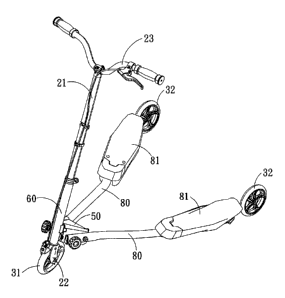
Referring to FIG. 3, it shows a configuration drawing of using a head
tube reset mechanism for a scooter, according to the present invention.
The head tube reset mechanism is basically constructed by a connector
50 for installing rear wheels 32, and a head tube 60 for installing a front
wheel 31 and a handle 23. As shown in FIG. 4 and FIG. 5 at a same
time, a front end of the connector 50 is provided with a jacket tube 55,
and a filling slot 511 that keeps a predetermined spacing from the jacket
tube 55. Upon implementing, the connector 50 can be made by
welding a stamping panel 51 with the jacket tube 55, and the filling slot
511 is disposed between the jacket tube 55 and the stamping panel 51.
In addition, the jacket tube 55 can be sheathed with a sliding sleeve 52,
thereby providing the connector 50 that is relatively light in weight.
The head tube 60 is installed at the front end of the connector 50,
and is provided with a pivot 61 that is sheathed into the jacket tube 55
and a limiting unit 62 that is extended into the filling slot 511. Upon
implementing, the limiting unit 62 can be constructed by connecting two
panels 621 that are fixed on the head tube 60. Ends of the two panels
CA 02812331 2013-03-27
621 opposite to the head tube 60 can be engaged together by welding to
form a plate with structural intensity. Ends of the two panels 621 facing
the head tube 60, on the other hand, are folded into a joint part to be
engaged with the head tube 60. The joint part of the two panels 621 is
also welded on the head tube 60.
At least an elastomer 70 is installed between the filling slot 511 of
the connector 50 and the limiting unit 62 of the head tube 60. As shown
in an embodiment in FIG. 5, for the entire head tube reset mechanism,
an elastomer 70 is installed between the filling slot 511 of the connector
50 and the limiting unit 62 of the head tube 60. The elastomer 70 is
installed in the filling slot 511 of the connector 50, and a front end of the
elastomer 70 is formed with an interference part 71 for insertion with the
limiting unit 62 of the head tube 60.
Upon implementing, the elastomer 70 is a block made by PU
(Polyurethane) or rubber. By interference between the elastomer 70
and the limiting unit 62, the head tube 60 is limited. In addition, when
the head tube 60 swings left or right against the pivot 61 when being
subjected to an external force, the elastomer 70 can result in a buffering
effect to the head tube 60 (as shown in FIG. 6) and always provide a
resetting force to keep the head tube 60 at a central upright position.
11
CA 02812331 2013-03-27
Accordingly, by the abovementioned head tube reset mechanism for
a scooter, a scooter rider can turn the handle 23 and swing the handle 23
left and right at a same time to swing the front wheel 31 left and right, as
well as roll the scooter forward along an S-shaped route while the front
wheel 31 swings left and right, thereby achieving the effects of exercise
and entertainment for the entire scooter. Furthermore, the scooter can
glide more smoothly without wasting too much labor. In particular, the
assembly parts of the head tube reset mechanism are very simple, which
reduces material cost, assembling cost, and subsequent maintenance
fees.
Besides that, as shown in a second embodiment in FIG. 7, two
elastomers 70 can be installed between the filling slot 511 of the
connector 50 and the limiting unit 62 of the head tube 60. The two
elastomers 70 can be a block of elastomer respectively (as shown in FIG.
7) or a spring respectively (as shown in FIG. 8), and are disposed
respectively at two sides of the limiting unit 62 of the head tube 60, so as
to be installed in the filling slot 511 of the connector 50.
On the other hand, as shown in a fourth embodiment in FIG. 9, an
elastomer 70 is installed between the filling slot 511 of the connector 50
and the limiting unit 62 of the head tube 60. The filling slot 511 of the
12
CA 02812331 2013-03-27
connector 50 is a round hole and the elastomer 70 is an elastic cylinder
that is installed in the filling slot 511. The elastomer 70 is provided with
an interference part 71 for insertion with the limiting unit 62 of the head
tube 60. The limiting unit 62 is a rod-shaped unit that is fixed on the
head tube 60, and the interference part 71 of the elastomer 70 is a round
hole.
As shown in a fifth embodiment in FIG. 10, an elastomer 70 is
installed between the filling slot 511 of the connector 50 and the limiting
unit 62 of the head tube 60. The limiting unit 62 is constructed by a
slot-shaped plate that is fixed on the head tube 60, and an end of the
limiting unit 62 opposite to the head tube 60 is formed with an opening
67. The elastomer 70 is disposed in the limiting unit 62 and the
connector 50 is protruded at the filling slot 511 with a plate unit 512 that
is extended into the limiting unit 62. An end of the elastomer 70 facing
the connector 50 is provided with an interference part 71 for insertion
with the plate unit 512.
The elastomer 70 can be a square block as shown in the drawings,
or can be a cylinder. In addition, the abovementioned limiting unit is
constructed by a slot-shaped plate that is fixed on the head tube, and an
end of the limiting unit opposite to the head tube is formed with an
13
CA 02812331 2013-03-27
opening. Under a structural configuration that the connector is
protruded at the filling slot with a plate unit extending into the limiting
unit,
two elastomers are installed between the filling slot of the connector and
the limiting unit of the head tube. The two elastomers are disposed
respectively at two sides of the plate unit of the head tube, so as to be
installed in the limiting unit. Similarly, the two elastomers can be a
block of elastomer respectively or a spring respectively.
The head tube 60 and the connector 50 can be assembled quickly
only by sheathing the pivot 61 and the limiting unit 62 into the jacket tube
55 and the filling slot 511 of the connector 50 respectively, and by
installing the elastomers 70 to positions. Furthermore, the head tube
60 can be further provided at a tail end of the pivot 61 with an end cap 63
to prevent the pivot 61 from escaping out.
Under a structural configuration that the abovementioned head tube
reset mechanism is further provided at the tail end of the pivot 61 with an
end cap 63 to prevent the pivot 61 from escaping out, a root part of the
pivot 61 can be also sheathed with a flat washer 64 that is abutted at a
front end of the jacket tube 55 to reduce a friction force between an end
surface of the jacket tube 55 and the head tube 60. In addition, the
lining of the flat washer 64 can avoid direct abrasion to the end surface
14
CA 02812331 2013-03-27
of the jacket tube 55 or to the head tube 60.
Under a structural configuration that the abovementioned head tube
reset mechanism is further provided at the tail end of the pivot 61 with an
end cap 63 to prevent the pivot 61 from escaping out, whether or not a
root part of the pivot 61 is sheathed with a flat washer 64 that is abutted
at a front end of the jacket tube 55, the end cap 63 can be locked at the
tail end of the pivot 61 by a set screw 65 that is screwed with the pivot
61.
Moreover, under a structural configuration that the abovementioned
end cap 63 is locked at the tail end of the pivot 61 by the set screw 65
which is screwed with the pivot 61, the pivot 61 can be a hollow tube.
Besides that, an interior of the pivot 61 is welded with a screw. fastener
66 that is screwed with the set screw 65, so that the end cap 63 can be
locked at the tail end of the pivot 61 and can be prevented from escaping
out. In addition, the head tube 60 and the connector 50 can be
assembled and dismantled conveniently.
It is worthy of mentioning that the head tube reset mechanism for a
scooter, according to the present invention, includes the connector 50 for
installing the rear wheels 32 and the head tube 60 for installing the front
wheel 31 and the handle 23. Therefore, the assembly structure of the
CA 02812331 2013-03-27
rear wheels and the assembly structure of the front wheel can be
changed quickly, and the rear wheel assembly structure can be even
quickly swapped with the front wheel assembly structure, thereby
facilitating the modularized design for the scooter.
For example, as shown in the embodiment in FIG. 3, the connector
.50 is provided with two rod members 80 and a tail end of each rod
member 80 is installed with a rear wheel 32. In addition, the head tube
60 can be sheathed with a stem 21 that can rotate freely. An upper end
of the stem 21 is installed with a handle 23 and a lower end of the stem
21 is installed with a front fork 22 and a front wheel 31. Therefore, a
scooter that can be ridden stably is achieved.
It is preferred that the two sides of the connector 50 are extended
backward and outward in a diagonal direction and two side walls of the
connector 50 can be further provided with a predetermined number of
filling holes 53, so that the rod members 80 and the connector 50 can be
assembled quickly by the filling holes 53, and the rod members 80 at the
two sides of the connector 50 can be stretched backward and outward
by a predetermined included angle. Therefore, the rear wheels 32 that
are installed at the tail ends of the two rod members 80 and the front
wheel 31 that is installed at the head tube 60 are in a triangular
16
CA 02812331 2014-10-24
17
configuration, which provides a more stable riding effect.
At least an elastic restoration element (not shown in the drawings) is
disposed
between the abovementioned each rod member 80 and the connector 50, so that
when riding the scooter, the rider can step his or her feet on the rod members
80 (or
footsteps 81 that are installed on the rod members 80) respectively, and carry
out
outward expansion and inward collection at a same time with the two feet
stepping on
the rod members 80. Therefore, while the two rod members 80 are continuously
collected inward and expanded outward, the two rear wheels 32 can swing along
with
the rod members 80 and move forward along an S-shaped route.
In comparison with the prior art, the head tube reset mechanism for a scooter,
according to the present invention, is provided with the simple structures,
which
reduces material cost, assembling cost and subsequent maintenance fees. In
particular, the entire head tube reset mechanism for a scooter is constructed
by the
connector for installing the rear wheels and the head tube for installing the
front
wheel and the handle, which facilitates the modularized design for the
scooter.
The scope of the claims should not be limited by the preferred embodiments
set forth in the examples, but should be given the broadest interpretation
consistent
with the description as a whole.