Note: Descriptions are shown in the official language in which they were submitted.
CA 02812489 2013-03-22
WO 2012/044602
PCT/US2011/053407
LIQUID MENISCUS LENS
INCLUDING MENISCUS WALL WITH MICROCHANNELS
RELATED APPLICATIONS
This application claims priority to Provisional Patent Application U.S. Serial
No.
61/387507 which was filed on September 29, 2010 and entitled, "LIQUID MENISCUS
LENS INCLUDING MENISCUS WALL WITH MICROCHANNELS", and as a
Continuation in Part Application to Non-Provisional Patent Application U.S.
Serial No.
13/095786 which was filed on April 27, 2011 and entitled "ARCUATE LIQUID
MENISCUS LENS", as well as Non-Provisional Patent Application U.S. Serial No.
13/149105 which was filed on May 31, 2011 and entitled "LENS WITH CONICAL
FRUSTUM MENISCUS WALL", as a Continuation in Part Application, the contents of
each of which are relied upon and incorporated by reference.
FIELD OF USE
The present invention relates generally to a liquid meniscus lens, more
specifically,
it includes an arcuate liquid meniscus lens with a meniscus wall containing
microchannels.
BACKGROUND
Liquid meniscus lenses have been known in various industries. As discussed
more
fully below with reference to Figs. lA and 1B, known liquid meniscus lenses
were
engineered in cylindrical shapes with a perimeter surface formed by points at
a fixed
distance from an axis which is a straight line. Known liquid meniscus lenses
have been
limited to designs with a first interior surface generally parallel to second
interior surface
and each perpendicular to a cylindrical axis. Known examples of the use of
liquid meniscus
lenses include devices such as electronic cameras.
Traditionally, an ophthalmic device, such as a contact lens and an intraocular
lens
included a biocompatible device with a corrective, cosmetic or therapeutic
quality. A
contact lens, for example, can provide one or more of: vision correcting
functionality;
1
CA 02812489 2013-03-22
WO 2012/044602
PCT/US2011/053407
cosmetic enhancement; and therapeutic effects. Each function is provided by a
physical
characteristic of the lens. A design incorporating a refractive quality into a
lens can provide
a vision corrective function. A pigment incorporated into the lens can provide
a cosmetic
enhancement. An active agent incorporated into a lens can provide a
therapeutic
functionality.
More recently, electronic components have been incorporated into a contact
lens.
Some components can include semiconductor devices. However, physical
constraints
including the size, shape and control aspects of a liquid meniscus lens have
precluded their
use in an ophthalmic lens. Generally the cylindrical shape, sometimes referred
to as the
"hockey puck" shape of liquid meniscus lenses, has not been conducive to
something that
can work in a human eye environment.
In addition, a curved liquid meniscus lens includes physical challenges that
are not
necessarily present in a traditional design of a liquid meniscus lens with
parallel sidewalls
and/or optical windows.
SUMMARY
Accordingly, the present invention provides a liquid meniscus lens. Some
preferred
embodiments include an arcuate front curve lens and an arcuate back curve
lens. The
present invention provides for a meniscus wall with physical features
conducive for one or
both of attraction and repulsion of a liquid contained within the lens and
forming a meniscus
with another liquid.
According to the present invention, a first optic is proximate to a second
optic with a
cavity formed therebetween. Preferred embodiments include a first arcuate
shaped optic
proximate to a second arcuate shaped optic with a cavity formed therebetween.
A saline
solution and an oil are maintained within the cavity. Application of an
electrostatic charge
to a meniscus wall generally located in a perimeter area of one or both of the
first optic and
the second optic changes the physical shape of a meniscus formed between the
saline
solution and oil maintained within the cavity.
The present invention includes a meniscus wall formed into a shape essentially
including a frustum of a cone, said wall containing microchannels.
2
CA 02812489 2013-03-22
WO 2012/044602
PCT/US2011/053407
DESCRIPTION OF THE DRAWINGS
Fig. lA illustrates a prior art example of a cylindrical liquid meniscus lens
in a first
state.
Fig. 1B illustrates the prior art example of a cylindrical liquid meniscus
lens in a
second state.
Fig. 2 illustrates a profile sliced cut away of an exemplary liquid meniscus
lens
according to some embodiments of the present invention.
Fig. 3 illustrates a cross section of a portion of an exemplary arcuate liquid
meniscus
lens, according to some embodiments of the present invention.
Fig. 4 illustrates additional exemplary aspects of an arcuate liquid meniscus
lens.
Fig. 5 illustrates meniscus wall elements within an arcuate liquid meniscus
lens,
according to some embodiments of the present invention.
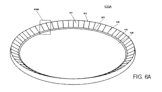
Fig. 6A illustrates a perspective view of a linear meniscus wall with
microchannels,
according to some embodiments of the present invention.
Fig. 6B illustrates a perspective view of a detailed section of a linear
meniscus wall
with microchannels, according to some embodiments of the present invention.
DETAILED DESCRIPTION OF THE INVENTION
The present invention provides for a liquid meniscus lens with at least one of
a front
curve lens and a back curve lens defining a meniscus cavity of the liquid
meniscus lens.
Some preferred embodiments include one or both of the front curve lens and the
back curve
lens including an arcuate surface. Other embodiments include one or both of
the front curve
lens and the back curve lens being relatively planar and with microchannels
included in a
meniscus wall.
GLOSSARY
3
CA 02812489 2013-03-22
WO 2012/044602
PCT/US2011/053407
In this description and claims directed to the presented invention, various
terms may
be used for which the following definitions will apply:
Contact Angle: The angle at which the oil/saline solution interface, also
referred to
as the liquid meniscus boundary, meets the meniscus wall. In the case of a
linear meniscus
wall, the contact angle is measured as the angle between the meniscus wall and
the line
tangent to the liquid meniscus boundary at the point where the liquid meniscus
boundary
meets the meniscus wall. In the case of a curved meniscus wall, the contact
angle is
measured as the angle between the lines tangent to the meniscus wall and the
liquid
meniscus boundary at the point where they meet.
Lens: As used herein, a Lens means an article with a front surface and a back
surface that is optically transmissive to a predefined range of wavelengths of
radiation, such
as, by way of example, visible light. A lens may include one or both of a
front surface and a
back surface which are essentially flat or one or both of a front surface and
a back surface
which are arcuate in shape.
Liquid Meniscus Boundary: The arcuate surface interface between the saline
solution and the oil. Generally, the surface will form a lens that is concave
on one side and
convex on the other.
Meniscus Cavity: The space in an arcuate liquid meniscus lens between the
front
curve lens and the back curve lens in which oil and saline solution are
maintained.
Meniscus Wall: A specific area on the interior of the front curve lens, such
that it is
within the meniscus cavity, along which the liquid meniscus boundary moves.
Optical Zone: as used herein refers to an area of an ophthalmic lens through
which a
wearer of the ophthalmic lens sees.
Sharp: A geometric feature of an internal surface of either a front curve or
back
curve lens piece sufficient to contain the location of a contact line of two
predefined fluids
on the optic. The sharp is usually an outside corner rather than an inside
corner. From a
fluid standpoint it is an angle greater than 180 degrees.
Referring now to Fig. 1A, a cut away view of a prior art lens 100 is
illustrated with
an oil 101 and a saline solution 102 contained within cylinder 110. The
cylinder 110
4
CA 02812489 2013-03-22
WO 2012/044602
PCT/US2011/053407
includes two plates of optical material 106. Each plate 106 includes an
essentially flat
interior surface 113-114. The cylinder 110 includes an interior surface that
is essentially
rotationally symmetric. In some prior art embodiments, one or more surfaces
may include a
hydrophobic coating. Electrodes 105 are also included on or about the
perimeter of the
cylinder. An electrical insulator may also be used proximate to the electrodes
105.
According to the prior art, each of the interior surfaces 113-114 is
essentially flat or
planar. An interface surface 112A is defined between the saline solution 102A
and the oil
101. As illustrated in Fig. 1A, the shape of the interface 112A is combined
with the
refractive index properties of the saline solution 102A and the oil 101 to
receive incident
light 108 through a first interior surface 113 and provide divergent light 109
through a
second interior surface 114. The shape of the interface surface between the
oil 101 and the
saline solution 102 may be altered with the application of an electrical
potential to the
electrodes 105.
Fig. lA illustrates a perspective view of the prior art lens illustrated at
100.
Referring now to Fig. 1B, the prior art lens 100 is illustrated in an
energized state.
The energized state is accomplished by applying voltage 114 across the
electrodes 115. The
shape of the interface surface 112B between the oil 101 and the saline
solution 102B is
altered with the application of an electrical potential to the electrodes 115.
As illustrated in
Fig. 1B, incident light 108B passing through the oil 101 and the saline
solution 102B is
focused into a convergent light pattern 111.
Referring now to Fig. 2, a cut away view of a liquid meniscus lens 200 with a
front
curve lens 201 and a back curve lens 202. In various embodiments, the front
curve lens 201
and the back curve lens 202 may include an arcuate lens or a substantially
flat lens. In some
preferred embodiments, the front curve lens 201 and the back curve lens 202
are positioned
proximate to each other and form a cavity 210 therebetween. The front curve
lens 201
includes a concave arcuate interior lens surface 203 and a convex arcuate
exterior lens
surface 204. The concave arcuate interior lens surface 203 may have one or
more coatings
(not illustrated in Fig. 2). Coatings may include, for example, one or more of
electrically
conductive materials or electrically insulating materials, hydrophobic
materials or
hydrophilic materials. One or both of the concave arcuate interior lens
surface 203 and the
CA 02812489 2013-03-22
WO 2012/044602
PCT/US2011/053407
coatings are in liquid and optical communication with an oil 208 contained
within the cavity
210.
The back curve lens 202 includes a convex arcuate interior lens surface 205
and a
concave arcuate exterior lens surface 206. The convex arcuate interior lens
surface 205 may
have one or more coatings (not illustrated in Fig. 2). Coatings may include,
for example,
one or more of electrically conductive materials or electrically insulating
materials,
hydrophobic materials or hydrophilic materials. At least one of the convex
arcuate interior
lens surface 205 and the coatings are in liquid and optical communication with
a saline
solution 207 contained within the cavity 210. The saline solution 207 includes
one or more
salts or other components which are ionically conductive and as such may be
either attracted
to or repulsed by an electric charge.
According to the present invention, an electrically conductive coating 209 is
located
along at least a portion of a periphery of one or both of the front curve lens
201 and the back
curve lens 202. The electrically conductive coating 209 may include gold or
silver and is
preferably biocompatible. Application of an electrical potential to the
electrically
conductive coating 209 creates either an attraction or a repulsion of the
ionically conductive
salts or other components in the saline solution 207.
The front curve lens 201 has an optical power in relation to light passing
through the
concave arcuate interior lens surface 203 and a convex arcuate exterior lens
surface 204.
The optical power may be 0 or may be a plus or minus power. In some preferred
embodiments, the optical power is a power typically found in corrective
contact lenses, such
as, by way of non-limiting example, a power between -8.0 and +8.0 diopters.
The back curve lens 202 has an optical power in relation to light passing
through the
convex arcuate interior lens surface 205 and a concave arcuate exterior lens
surface 206.
The optical power may be 0 or may be a plus or minus power. In some
embodiments, the
optical power is a power typically found in corrective contact lenses, such
as, by way of
non-limiting example, a power between -8.0 and +8.0 diopters. An optical axis
212 is
formed through the back curve lens 202 and the front curve lens 201.
Various embodiments may also include a change in optical power associated with
a
change in shape of a liquid meniscus 211 formed between the saline solution
207 and the oil
6
CA 02812489 2013-03-22
WO 2012/044602
PCT/US2011/053407
208. In some embodiments, a change in optical power may be relatively small,
such as, for
example, a change of between 0 to 2.0 diopters of change. In other
embodiments, a change
in optical power associated with a change in shape of a liquid meniscus may be
up to about
30 or more diopters of change. Generally, a higher change in optical power
associated with
a change in shape of a liquid meniscus 211 is associated with a relatively
increased lens
thickness 213.
According to some embodiments of the present invention, such as those
embodiments that may be included in an ophthalmic lens, such as a contact
lens, a cross cut
lens thickness 213 of an arcuate liquid meniscus lens 200 will be up to about
1,000 microns
thick. An exemplary lens thickness 213 of a relatively thinner lens 200 may be
up to about
200 microns thick. Preferred embodiments may include a liquid meniscus lens
200 with a
lens thickness 213 of about 600 microns thick. Generally a cross cut thickness
of front
curve lens 201 may be between about 35 microns to about 200 microns and a
cross cut
thickness of a back curve lens 202 may also be between about 35 microns and
200 microns.
Typically, a cross-sectional profile includes a defined variance in thickness
at different
locations in the lens 200.
According to the present invention, an aggregate optical power is an aggregate
of
optical powers of the front curve lens 201 the back curve lens 202 and a
liquid meniscus
211formed between the oil 208 and the saline solution 207. In some
embodiments, an
optical power of the lens 200 will also include a difference in refractive
index as between
one or more of the front curve lens 201, the back curve lens 202, the oil 208
and the saline
solution 207.
In those embodiments that include an arcuate liquid meniscus lens 200
incorporated
into a contact lens, it is additionally desirous for the saline 207 and oil
208 to remain stable
in their relative positions within the arcuate liquid meniscus lens 200 as a
contact wearer
moves. Generally, it is preferred to prevent the oil 208 from floating and
moving relative to
the saline 207 when the wearer moves. Accordingly, an oil 208 and saline
solution 207
combination is preferably selected with a same or similar density.
Additionally, an oil 208
and a saline solution 207 preferably have relatively low miscibility so that
the saline
solution 207 and oil 208 will not mix.
7
CA 02812489 2013-03-22
WO 2012/044602
PCT/US2011/053407
In some preferred embodiments, a volume of saline solution 207 contained
within
the cavity 210 is greater than the volume of oil 208 contained within the
cavity 210.
Additionally, some preferred embodiments include the saline solution 207 in
contact with
essentially an entirety of an interior surface 205 of the back curve lens 202.
Some
embodiments may include a volume of oil 208 that is about 66% or more by
volume as
compared to an amount of saline solution 207. Some additional embodiments may
include
an arcuate liquid meniscus lens wherein a volume of oil 208 is about 90% or
less by volume
as compared to an amount of saline solution 207.
Referring now to Fig. 3, a cutaway of an edge portion of an arcuate liquid
meniscus
lens 300 is illustrated. As discussed above, an arcuate liquid meniscus lens
300 includes
combined front curve lens 301 and back curve lens 302 components. The front
curve lens
301 and back curve lens 302 may be formed with one or more materials that are
at least
partially transparent. In some embodiments, one or both of the front curve
lens 301 and the
back curve lens 302 include generally optically clear plastic, such as for
example, one or
more of: PMMA, Zeonor and TPX.
One or both of the front curve lens 301 and the back curve lens 302 may be
fashioned, for example via processes such as one or more of: single point
diamond turning
lathing; injection molding; digital mirror device free forming.
One or both of the front curve lens 301 and the back curve lens 302 may
include a
conductive coating 303, as illustrated, the conductive coating 303 extending
along a
perimeter portion from 309 to 310. In some preferred embodiments, a conductive
coating
303 includes gold. The gold may be applied via a sputter process, vapor
deposition or other
known process. Alternative conductive coating 303 may include, by way of non-
limiting
example, aluminum, nickel, and indium tin oxide. Generally, the conductive
coating 303
will be applied to perimeter areas of one or both of the front curve lens 301
and the back
curve lens 302.
In some embodiments of the present invention, a back curve lens 302 has a
conductive coating 304 applied to specific areas. For example, portions about
the perimeter
of the back curve lens 302 may be coated from a first boundary 304-1 to a
second boundary
304-2. The gold coatings may be applied for example via a sputter process or a
vapor
8
CA 02812489 2013-03-22
WO 2012/044602
PCT/US2011/053407
deposition. In some embodiments, a mask may be used to apply the gold or other
conductive material in a predetermined pattern around one or more perimeter
portions of a
front curve lens 301 or a back curve lens 302. Alternative conductive
materials may be
applied using various methods and covering varying areas of the back curve
lens 302.
In some embodiments, a conductive pass through, such as, for example one or
more
holes or slots in a back curve lens 302 may be filled with a conductive filler
material, such
as, for example, a conductive epoxy. The conductive filler may provide
electrical
communication to a conductive coating on an interior surface of one or both of
the front
curve lens 301 and the back curve lens 302.
In another aspect of the present invention, one or both of the front curve
lens 301
and the back curve lens 302 may be created from multiple different materials
wherein an
optical zone generally in a central area of the front curve lens 301 and the
back curve lens
302 (not illustrated) may include an optically transparent material and a
peripheral zone may
include an optically opaque area that includes an electrically conductive
material. The
optically opaque area may also include one or more of control circuitry and
energy sources.
In still another aspect, in some embodiments, an insulator coating 305 is
applied to a
front curve lens 301. By way of non-limiting example, the insulator coating
305 may be
applied in an area from a first region 305-1 and extend to a second region 305-
2. Insulators
may include, for example, Parylene CTM, Teflon AF or other materials with
various
electrical and mechanical characteristics and electrical resistance.
In some specific embodiments, an insulator coating 305 creates a boundary area
to
maintain separation between the conductive coating 303 and a saline solution
306 contained
in a cavity between the front curve lens 301 and the back curve lens 302. Some
embodiments accordingly include an insulator coating 305 patterned and
positioned in one
or more areas of one or both of the front curve lens 301 and the back curve
lens 302 to
prevent a positively charged conductor 303 and negatively charged saline
solution 306 from
coming into contact, wherein contact of a conductor 303 and a saline solution
306 will result
in an electrical short circuit. Embodiments may include a positively charged
saline solution
306 and a negatively charged conductor 303.
9
CA 02812489 2013-03-22
WO 2012/044602
PCT/US2011/053407
Still other embodiments may allow for a short circuit between a conductor 303
and a
saline solution 306 as a reset function of circuitry associated with the
operation of the lens
300. For example, a short circuit condition may equalize potential applied to
the lens and
cause the saline solution 306 and the oil 307 to revert to a default position.
Some preferred embodiments include a conductor 303 that extends from an area
309
on the interior of the cavity 311 to an area 310 external to the cavity 311.
Other
embodiments may include a channel 312 through the front curve lens or the back
curve lens
which may be filled with a conductive material 313, such as, for example, a
waterproof
conductive epoxy. The conductive material 313 may form or be connected to an
electrical
terminal external to the cavity. An electrical potential may be applied to the
terminal and
conducted to the coating via the conductive material 313 in the channel 312.
The thickness of the insulator coating 305 may be varied as a parameter of
lens
performance. According to the present invention, charged components, including
the saline
solution 306 and the conductor 303, are generally maintained on either side of
the insulator
coating 305. The present invention provides for an indirect relationship
between the
thickness of the insulator coating 305 and an electrical field between the
saline solution 306
and the conductor 303, wherein the farther apart the saline solution 306 and
the conductor
303 are maintained, the weaker the electrical field will be.
Generally, the present invention provides that electrical field strength may
fall off
dramatically as insulator coating 305 thickness increases. The closer together
the fields are,
the more energy that will generally be available to move a spherical liquid
meniscus
boundary 308. As a distance between the saline solution 306 and conductor 303
increases,
the farther apart electrostatic charges of the saline solution 306 and the
conductor coating
303 will be and therefore the harder it is to get the spherical liquid
meniscus boundary 308
to move. Inversely, the thinner the insulator coating 305, the more
susceptible is the lens to
defects in an insulator coating 305. Generally, even a relatively small hole
in the insulator
coating 305 will create an electrical short circuit and the lens will not
function in an
electrowetting fashion.
In some embodiments, it is desirable to include a saline solution 306 with
density
that is generally the same density of an oil 307 also contained within the
lens 300. For
CA 02812489 2013-03-22
WO 2012/044602
PCT/US2011/053407
example, a saline solution 306 may preferably include a density that is within
10% of a
density of an oil 307 and more preferably the saline solution 306 will include
a density
within 5% of a density of an oil and most preferably within about 1% or less.
In some
embodiments, a concentration of salts or other components within the saline
solution 306
may be adjusted to adjust the density of the saline solution 306.
According to the present invention, an arcuate liquid meniscus lens 300 will
provide
a more stable optical quality by limiting movement of the oil 307 in relation
to the front
curve lens 301 and the back curve lens 302. One method of maintaining
stability of
movement of the oil 307 in relation to one or both of the arcuate front curve
lens 301 and
the back curve lens 302 is to maintain a relatively congruent density in the
oil 307 and the
saline solution 306. In addition, due to the curve design of the interior
surfaces of both the
front curve lens 301 and the back curve lens 302, the relative depth or
thickness of a layer of
saline solution 306 is diminished as compared to a traditional cylindrical
lens design. In this
scenario, the interfacial forces acting on fluids within the cavity may have a
relatively
greater contribution toward maintaining an unperturbed liquid meniscus
boundary 308.
Consequently, the density matching requirement may become more relaxed in such
cases.
In some embodiments, the relative thinness of the fluid layers further
supports the liquid
lens boundary 308.
In some preferred embodiments, the saline solution 306 provides a low
refractive
index as compared to the oil 307 which provides a relatively high refractive
index.
However, in some embodiments it is possible to include a saline solution 306
with a higher
refractive index as compared to the oil 307 which in such cases provides a
relatively lower
refractive index.
An adhesive 314 may be used to secure the front curve lens 301 and back curve
lens
302 in place proximate to each other, thereby retaining the oil 307 and saline
solution 306
therebetween. The adhesive 314 acts as a seal so that there is no leakage of
saline solution
306 or oil 307 from the curved liquid meniscus lens 300.
Referring now to Fig. 4, a curved liquid meniscus lens 400 is illustrated with
a liquid
meniscus boundary 401 between the saline solution 406 and oil 407. According
to some
preferred embodiments, a meniscus wall 405 is defined in the front curve lens
404 by a first
11
CA 02812489 2013-03-22
WO 2012/044602
PCT/US2011/053407
angular break in an arcuate wall extending between 402 and 403. The liquid
meniscus
boundary 401 will move up and down the meniscus wall 405 as electrical
potential is
applied and removed along one or more conductive coatings or conductive
materials 408.
In some preferred embodiments, a conductive coating 408 will extend from an
area
internal to the cavity 409 holding the saline solution 406 and the oil 407 to
an area external
to the cavity 409 containing the saline solution 406 and oil 407. In such
embodiments, the
conductive coating 408 may be a conduit of an electrical potential applied to
the conductive
coating 408 at a point external to the cavity 409 to an area of the conductive
coating 408
within the cavity 409 and in contact with the saline solution 406.
Referring now to Fig. 5, a cut away view of an edge portion of an arcuate
liquid
meniscus lens 500 is shown with a front curve lens 501 and a back curve lens
502. The
arcuate liquid meniscus lens 500 may contain saline solution 503 and oil 504.
The geometry
of the arcuate liquid meniscus lens 500 and the characteristics of the saline
solution 503 and
oil 504 facilitate formation of a liquid meniscus boundary 505 between the
saline solution
503 and oil 504.
Generally, a liquid meniscus lens may be viewed as a capacitor with one or
more of:
conductive coatings, insulator coatings, pathways, and materials present on or
through the
front curve lens 501 and back curve lens 502. According to the present
invention, a shape
of a liquid meniscus boundary 505 and therefore a contact angle between the
liquid
meniscus boundary 505 and the front curve lens 501 change in response to an
electrical
potential applied to a surface of at least a portion of one or both of the
front curve lens 501
and the back curve lens 502.
According to the present invention, a change in an electrical potential
applied to the
saline solution 503 via the conductive coatings or materials changes a
position of the liquid
meniscus boundary 505 along a meniscus wall 506. The movement takes place
between a
first sharp 506-1 and a second sharp 506-2.
In preferred embodiments, the liquid meniscus boundary 505 will be at or near
the
first sharp 506-1 when a first magnitude of electrical potential is applied to
the lens, such as,
for example, a voltage and current correlating with an unpowered state or
resting state.
12
CA 02812489 2013-03-22
WO 2012/044602
PCT/US2011/053407
Application of a second magnitude of electrical potential, sometimes referred
to as a
first powered state, may correlate with a movement of the liquid meniscus
boundary 505
along the meniscus wall 506 generally in the direction of the second sharp 506-
2, causing
the shape of the liquid meniscus boundary to change.
An applied voltage for transitioning between a first powered state and a
second
powered state may include, for example, a direct current voltage of between
about 5 volts to
about 60 volts. In other embodiments an alternating current voltage may also
be utilized.
In some embodiments, the meniscus wall 506 will be a smooth surface in
relation to
the thickness of the insulator coating. A smooth meniscus wall 506 surface may
minimize
defects in the insulator coating. Additionally, because random irregularities
in surface
texture may result in uneven fluid motion and therefore cause uneven or
unpredictable
meniscus motion when energizing or de-energizing the lens, a smooth meniscus
wall 506 is
preferred. In some preferred embodiments, a smooth meniscus wall includes a
peak to
valley measurement along the meniscus wall 506 in the range of between about
1.25
nanometers to 5.00 nanometers.
In another aspect, in some embodiments, it is desirable for the meniscus wall
506 to
be hydrophobic, in which case a defined texture, such as a nano-textured
surface, may be
incorporated in the design of the arcuate liquid meniscus lens.
In still another aspect, in some embodiments, the meniscus wall 506 may be
angled
relative to an optical axis of the lens. The angle can range from 00, or
parallel to the optical
axis, to at or near 90 , or perpendicular to the optical axis. As illustrated,
and in some
preferred embodiments, the meniscus wall 506 angle is generally between about
30 and 50
in order for the arcuate liquid meniscus lens to function given the current
contact angle
between the liquid meniscus boundary 505 and the insulator-coated meniscus
wall 506.
With the use of different materials or with different optical objectives, such
as telescopic
vision, the angle of the meniscus wall 506 may be closer to 00 or 90 .
According to the present invention, an angle of a meniscus wall 506 may be
designed to accommodate a magnitude of movement along a meniscus wall 506 upon
application of a specified electrical voltage. In some embodiments, as
meniscus wall 506
angle increases, the ability to change lens power generally decreases within
given lens size
13
CA 02812489 2013-03-22
WO 2012/044602
PCT/US2011/053407
and voltage parameters. Additionally, if the meniscus wall 506 is at or near 0
relative to the
optical axis, the liquid meniscus boundary 505 will be steered nearly straight
onto the front
optic. Meniscus wall angle is one of several parameters that can be tailored
to provide
various outcomes in lens performance.
In some preferred embodiments, the meniscus wall 506 is approximately 0.265 mm
in length. However, the angle of the meniscus wall 506 together with the size
of the overall
lens will naturally affect meniscus wall 506 length in various designs.
It may generally be considered that an arcuate liquid meniscus lens 500 will
fail if
the oil 504 contacts the back curve lens 502. Therefore, in preferred
embodiments, the
meniscus wall 506 is designed to allow a minimum clearance of 50 microns
between the
first sharp 506-1 and the back curve lens 502 at its nearest point. In other
embodiments, the
minimum clearance may be less than 50 microns, although the risk of lens
failure increases
as the clearance is reduced. In yet other embodiments, the clearance may be
increased to
mitigate the risk of lens failure, but the overall lens thickness will also
increase which may
be undesirable.
In still another aspect of some preferred embodiments of the present
invention, the
behavior of a liquid meniscus boundary 505 as it travels along a meniscus wall
506 may be
extrapolated using Young's Equation. Although Young's Equation defines the
balance of
forces caused by a wet drop on a dry surface and assumes a perfectly flat
surface, the
fundamental properties can be applied to the electrowetted lens environment
created within
the arcuate liquid meniscus lens 500.
A first magnitude of electrical energy may be applied to the lens, such as,
for
example, when the lens is in an unpowered state. During the application of the
first
magnitude of electrical energy, a balance of interfacial energies between the
oil 504 and
saline solution 503 is achieved. Such a state may be referred to herein as a
liquid meniscus
boundary 505. The oil 504 and meniscus wall 506, and the saline solution 503
and
meniscus wall 506, form an equilibrium contact angle between the liquid
meniscus
boundary 505 and the meniscus wall 506. When a change in magnitude of voltage
is
applied to the arcuate liquid meniscus lens 500, the balance of interfacial
energies will
change, resulting in a corresponding change in contact angle between the
liquid meniscus
boundary 505 and the meniscus wall 506.
14
CA 02812489 2013-03-22
WO 2012/044602
PCT/US2011/053407
The contact angle of the liquid meniscus boundary 505 with the insulator-
coated
meniscus wall 506 is an important element in the design and function of the
arcuate liquid
meniscus lens 500 not only due to its role in the Young's Equation in movement
of the
liquid meniscus boundary 505, but also because the contact angle is used in
conjunction
with other features of the arcuate liquid meniscus lens 500 to limit meniscus
movement.
Discontinuities, such as sharps 506-1 and 506-2, at both ends of the meniscus
wall
506 act as boundaries for liquid meniscus 505 movement because it would
require a
significant change in applied electrical potential to effect a large enough
change in liquid
meniscus contact angle to move the liquid meniscus boundary 505 past one of
the sharps.
By way of non-limiting example, in some embodiments, a contact angle of the
liquid
meniscus boundary 505 with the meniscus wall 506 is in the range of 15 to 40
whereas the
contact angle of the liquid meniscus boundary 505 with the step 507 beyond the
second
sharp 506-2 is perhaps in the range of 90 to 130 and in some preferred
embodiments about
110 .
A voltage may be applied to the lens, resulting in movement of the liquid
meniscus
boundary 505 along the meniscus wall 506 toward the second sharp 506-2. The
natural
contact angle of the liquid meniscus boundary 505 with the insulator-coated
meniscus wall
506 will cause the liquid meniscus boundary 505 to stop at the second sharp
506-2 unless
significantly more voltage is supplied.
At one end of the meniscus wall 506, a first sharp 506-1 generally defines one
limit
beyond which the liquid meniscus boundary 505 will not typically move. In some
embodiments, the first sharp 506-1 is constructed as a sharp edge. In other
preferred
embodiments, the first sharp 506-1 has a defined small radial surface which
can be created
with less possibility of defect. Conductive, insulator, and other possible
desired coatings
may not deposit evenly and predictably on a sharp edge, whereas a defined
radius edge of
the radial surface can be coated more reliably.
In some embodiments, the first sharp 506-1 is constructed at about a 90 angle
with
a defined radius of about10 microns. The sharp may also be created with less
than a 90
angle. In some embodiments, a sharp with a larger angle than 90 may be used
to increase
the sturdiness of the sharp, but the design would then take up more lens
space.
CA 02812489 2013-03-22
WO 2012/044602
PCT/US2011/053407
In various embodiments, a defined radius of a sharp 506-1 and/or 506-2 may be
in
the range of 5 microns to 50 microns. A larger defined radius may be used to
improve the
reliability of the coatings, but at the cost of using more space within the
tight confines of the
lens design. In this, as in many other areas of lens design, tradeoffs exist
between ease of
construction, optimization of lens functions, and minimizing size. A
functional, reliable
arcuate liquid meniscus lens 500 may be made using a wide range of variables.
In some embodiments, a larger sharp radius may be used in conjunction with an
improved surface finish on a side-wall between two adjacent sharps. In some
embodiments,
it may be desirable that a surface from a first radius (sharp) to a second
radius (sharp) be
smooth and without discontinuities wherein it is helpful to cut a mold used to
fashion a
sharp with the same tool. Radii included in a sharp may be cut into a mold
tool surface,
wherein the mold tool surface radius is larger than the sharp radius. Wherein
the mold tool
surface is a continuous surface including one or more sharps and a side wall.
A larger tool
radius may generally relate to a smoother surface finish of a corresponding
cut.
A second sharp 506-2, includes a feature designed to limit oil movement when
voltage is applied to the arcuate liquid meniscus lens 500. The second sharp
506-2 may also
include, in some embodiments a generally pointed end, or in other embodiments,
the second
sharp 506-2 may include a defined radius of between 5 and 25 microns, most
preferred 10
microns. A 10 micron radius performs well as a sharp and can be created using
single point
diamond turning lathe or injection molding processes.
A vertical or nearly vertical step 507, extending to a start of the optical
area 508 of
the front curve lens 501 may be included on a side of the second sharp 506-2
opposing the
meniscus wall 506. In some embodiments, the step 507 is 120 microns in height,
although it
could be in the range of 50 to 200 microns.
In some embodiments, the step 507 may be angled at about 50 from optical axis.
In
other embodiments, the step 507 angle may be as little as 10 or 2 or may be
angled more
than 5 . A step 507 that is less angled from optical axis will generally act
as a more
effective limiter of meniscus movement because it would require a greater
change in the
contact angle of the liquid meniscus boundary 505 to move off of the meniscus
wall 506 and
onto the step 507. The transition from the step 507 to the start of the
optical area 508 is a 25
micron radius. A larger radius would unnecessarily consume more space within
the lens
16
CA 02812489 2013-03-22
WO 2012/044602
PCT/US2011/053407
design. A smaller radius is possible and may be implemented if necessary to
gain space.
The decision to use a defined radius rather than a theoretical sharp in this
area as well as
others in the lens is based, in part, on the potential move to an injection
molding process for
lens elements. A curve between the step 507 and the start of the optical area
508 will
improve plastic flow during the injection molding process and result in a lens
with optimal
strength and stress-handling characteristics.
Referring now to Fig. 6A, a perspective view depicts a portion of a front
curve lens
including a meniscus wall with microchannels 601, a step 605, and an optical
zone 606. A
first sharp 602 and a second sharp 603 are shown, between which is found a
meniscus wall
with microchannels 601. In the present embodiment, the meniscus wall with
microchannels
601 generally forms the shape of a conical frustum, a cross section of which
shows the
meniscus wall to be linear. Examples of a lens including a linear meniscus
wall are
described in the U.S. Patent Application Serial Number 61,359,548, filed June
29, 2010 and
entitled, "LENS WITH CONICAL FRUSTUM MENISCUS WALL", which is incorporated
herein by reference. In some embodiments, a microchannel meniscus wall design
may be
included on meniscus walls of varying shapes, such as by way of non-limiting
example, a
convex torus-segment meniscus wall, a concave torus-segment meniscus wall, a
compound
linear-convex meniscus wall, a multi-convex meniscus wall, a multi-concave
meniscus wall,
and a multi-segmented linear meniscus wall.
Referring now to Fig. 6B, a detailed view of a portion of a meniscus wall with
microchannels 601 is shown including two microchannels 604. In some
embodiments, one
end of each microchannel 604 is near but not intersecting a first sharp 602,
while the other
end of each microchannel 604 extends past a second sharp 603, part way down a
step 605
toward an optical area 606 of a front curve lens. According to the present
invention, the
boundary between a side of a microchannel 604 and an adjacent meniscus wall
section 601
is generally a sharp edge. In other embodiments, the edge between a meniscus
wall 601 and
a microchannel 604 may include a defined radius.
When electrical potential is removed from a previously energized arcuate
liquid
meniscus lens, the liquid meniscus may be resistant to returning to a rest
position or de-
energized position. According to the present invention, microchannels 604 will
promote
17
CA 02812489 2013-03-22
WO 2012/044602
PCT/US2011/053407
rapid liquid meniscus movement, assisting in recovery of a liquid meniscus
back to a de-
energized position.
In some embodiments, additional oil volume may be retained within the
microchannel structures in the un-energized state. Upon energizing the liquid
lens, saline
solution will displace a portion of the oil volume within each microchannel,
resulting in a
larger magnitude of optical power change in the liquid lens for the same
effective natural
wetting fluid angle. In some preferred embodiments, microchannels 604 may
desensitize
liquid meniscus recovery rate to variability of other factors in lens
construction and
operation. Furthermore, oil droplets may be retained by the microchannel
structures when
the position of the liquid meniscus boundary is caused to change by applied
voltage. The oil
droplets assist with retraction of the liquid meniscus boundary when the lens
is de-
energized, leading to a faster and more predictable recovery time.
In still other embodiments, variations of meniscus wall design and texture may
promote rapid liquid meniscus movement and recovery. By way of non-limiting
example,
some meniscus wall variations include walls with microdimples, with connected
microdimples, with microgrooves positioned circumferentially, with spiral
microgrooves,
with crisscrossing micropatterns, with microribs, and with micronubs.
While the invention has been described with reference to particular
embodiments, it
will be understood by those skilled in the art that various changes may be
made and
equivalents may be substituted for elements thereof without departing from the
scope of the
invention. In addition, many modifications may be made to adapt a particular
situation or
material to the teachings of the invention without departing from the scope of
the invention.
Therefore, it is intended that the invention not be limited to the particular
embodiments disclosed as the best mode contemplated for carrying out this
invention, but
that the invention will include all embodiments falling within the scope and
spirit of the
appended claims.
18