Note: Descriptions are shown in the official language in which they were submitted.
MINIMALLY OBSTRUCTIVE RETRACTOR
[0001]
TECHNICAL FIELD
[0002] This invention relates generally to medical surgical instruments,
particularly structurally-adjustable retractors and speculums for
gynecological
examinations and operations.
BACKGROUND
[0003] Devices which have been proposed for the purpose of vaginal
examination and gynecological surgical procedures may not be entirely
satisfactory
for a variety of reasons. In many cases, they may obstruct the vision of the
deep
internal parts of the vaginal cavity that they are intended to expose. They
may also
constrain the movement of the physicians' hands and reduce the open work area
for
the surgeon. This often reduces the efficiency and effectiveness of vaginal
examinations and surgical procedures.
[0004] Furthermore, typically the vagina walls, the perineum (which is the
area
of tissue between the vagina and the anus), and the anus are torn during
vaginal
delivery. Natural perineal tears are classified by their severity. First-
degree tears
involve tearing only the skin. Second-degree tears involve tearing muscle.
Third-
degree tears involve tearing the external anal sphincter muscle. Fourth-degree
tears
further involve tearing the rectal mucosa. When fourth-degree tears occur, the
mother
may require post-birth surgery to stitch up the torn tissue, often under
general
anesthetic.
1
CA 2812694 2017-06-09
CA 02812694 2013-03-22
WO 2012/047725
PCT/US2011/054064
[0005] Sometimes the perineum is purposely cut by a doctor performing an
episiotomy, which is an incision into the perineum to enlarge the size of the
vaginal
opening. An episiotomy is similar to a first or second-degree natural tear.
[0006] All of the above tearing or incisions usually require post-delivery
operations
to stitch up the area. Stitching fourth-degree tears is particularly difficult
using
known specula given that fourth-degree tears typically extend from the vagina
wall
all the way to the rectum. Such surgery is extremely difficult due to the
flaccid
nature of the surrounding tissue which exists immediately after birth.
[0007] Episiotomy retractors for retracting friable postpartum vaginal tissue
to
facilitate repair of the episiotomy or vaginal laceration are known. The
primary
function of the retractor is to provide an open work area for the surgeon
about the
perineum and posterior vaginal wall of the patient so that the surgeon can
conveniently and safely approximate and suture the tissue planes to complete
repair.
[0008] The known episiotomy retractors may not be entirely satisfactory in
use.
Existing speculums may not permit access to the area in which the stitching is
required and furthermore may tend to interfere with the surgeons ability to
make the
stitches in the first place.
[0009] Most importantly, conventional retractors may fail to provide
sufficient open
work area for the surgeon about the perineum and the posterior vaginal wall of
the
patient. During the delivery process the labia of the patient may become
engorged
with blood and thus may tends to interfere with visualization of the desired
work
area by the surgeon.
[0010] Furthermore, conventional retractors often include scissor arms or
other
elongated portions for gripping and leverage. However, these elements may
increase the size and cost of the devices, and can constrain the movement of
the
physicians' hands and reduce the open work area for the surgeon.
SUMMARY
[0011] This application presents minimally obstructive retractors and
speculums
that afford an open work area of desirable size and enhanced visualization to
users
2
CA 02812694 2013-03-22
WO 2012/047725
PCT/US2011/054064
about the perineum and the posterior vaginal wall of the patient. The
retractor may
be lightweight, and configured and dimensioned to minimize slippage during
use.
The position of various elements of the device may be adjusted prior to,
during, and
after the procedure. The device may retract the engorged labia of the
postpartum
patient as well as the vaginal walls. The retractor may be simple and
inexpensive to
manufacture, use and maintain.
[0012] The device may provide several benefits, including but not limited to:
permitting two-handed surgical techniques, facilitating approximation of
tissue
layers, retaining its angle of retraction, preventing fluids and tissues from
obstructing the posterior vaginal wall and perineum, and promoting hemostasis.
[0013] The device may be used for improved visualization, access, and repair
in
various procedures, including, but not limited to: obstetrical/gynecological
procedures: vaginal inspection; perineal inspection; vaginal wound repair;
perineal
wound repair; episiotomy repair; female pelvic exam; pap smear; cervical
biopsy;
vaginal/pelvic reconstruction; urological procedures; colorectal, general, or
other
surgery; the device may be turned upside-down, for example, for female
urologic
procedures; access to the cervix (or uterus via cervix); IUD insertion,
removal, or
adjustment; and dilatation & curettage (dilatation of cervix and curettage of
uterus).
[0014] The minimally obstructive retractor has a proximal end and a distal
end,
and an exterior surface and an interior surface. In one embodiment, this
retractor
may comprise a central body portion, at least two wings, and at least two
hinges,
each configured to affix a different one of the at least two wings to the
central body
portion. The central body portion, the at least two wings, and the at least
two hinges
form a canopy.
[0015] In another embodiment, this canopy is formed such that the fluid flow
through the exterior surface of the canopy, defined by the exterior surfaces
of the
body, wings and hinges, is substantially blocked. In an example of this
embodiment, the hinges may be living hinges.
[0016] The minimally obstructive retractor may further comprise protruded
portions,
thinned portions, or combinations thereof. Such protruded or thinned portions
may
3
be formed on the exterior surface of the central body portion, the wing, or
both the
central body portion and the wing.
[0017] The minimally obstructive retractor may also comprise a ratchet
mechanism. This ratchet mechanism may have one arm that is affixed to the
interior
surface of at least one wing.
[0018] Furthermore, in one embodiment, the retractor may further comprise a
gripping proximal tip at the proximal end. Also, the retractor may further
comprise a
retractor limiter at the proximal end.
[0019] In some embodiments, the minimally obstructive retractor may further
comprise an illumination source. This illumination source may comprise at
least one
light-emitting diode. In one embodiment, the illumination source may be
located within
the canopy. In another embodiment, the light emitting diode may be located
within the
canopy. Yet, in another embodiment, the illumination source is automatically
turned
on in conjunction with movement of the ratchet arms away from each other
and/or
automatically turned off in conjunction with movement of the ratchet arms
towards
each other.
[0020] In other embodiments, the hinge may comprise polyethylene,
polypropylene, nylon, acetal plastics or a mixture thereof. The hinge may also
comprise polyethylene, polypropylene, or a mixture thereof.
[0021] In an embodiment, the retractor may further comprise a lubrication
source comprising a lubricant-containing reservoir integrated to the retractor
and
configured to provide lubricant to an outer surface of the retractor.
[0021a] In one embodiment, there is provided a minimally obstructive
retractor
having a proximal end, a distal end, an exterior surface, and an interior
surface. The
minimally obstructive retractor includes a central body portion, at least two
wings, and
at least two hinges. Each of the at least two hinges are configured to affix a
different
one of the at least two wings to the central body portion, the wings being
rotatable
about the hinges when moving from a closed to an open position. The wings, the
4
CA 2812694 2017-06-09
hinges, and the central body portion form a canopy that creates and only
partially
surrounds an interior space that is not surrounded by any other portion of the
retractor
when the wings are in the open position. No portion of the retractor obstructs
any
portion of a length of the interior space opposite the central body portion
between the
proximal end and the distal end when the wings are in the open position. The
minimally obstructive retractor further includes a ratchet mechanism that
releasably
locks the wings in the open position.
[0022] It is
understood that other embodiments of the devices and methods will
become readily apparent to those skilled in the art from the following
detailed
description, wherein it is shown and described only exemplary embodiments of
the
devices, methods and systems by way of illustration. As will be realized, the
devices,
systems and systems are capable of other and different embodiments and its
several
details are capable of modification in various other respects, all without
departing from
the spirit and scope of the invention. Accordingly, the drawings and
4a
CA 2812694 2017-06-09
CA 02812694 2013-03-22
WO 2012/047725
PCT/US2011/054064
detailed description are to be regarded as illustrative in nature and not as
restrictive.
BRIEF DESCRIPTION OF THE DRAWINGS
[0023] Aspects of the minimally obstructive retractor are illustrated by way
of
example, and not by way of limitation, in the accompanying drawings.
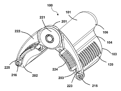
[0024] FIG 1 is an isometric view of an exemplary retractor.
[0025] FIG 2 is a side view of the exemplary retractor of FIG 1.
[0026] FIG 3 is a bottom view of the exemplary retractor of FIG 1.
[0027] FIG 4 is a rear view of the exemplary retractor of FIG 1.
[0028] FIG 5 is an isometric view of another exemplary retractor.
[0029] FIG 6 is a side view of the exemplary retractor of FIG 5.
[0030] FIG 7 is a rear view of the exemplary retractor of FIG 5.
[0031] FIG 8 is an isometric view of the exemplary retractor of FIG 5 without
a
ratchet mechanism.
[0032] FIG 9 is a retractor arm of the ratchet mechanism of the exemplary
ratchet
system of FIG 5.
[0033] FIG 10 is another retractor arm of the ratchet mechanism of Figure 5.
[0034] FIG 11 is an isometric view of separated parts of the ratchet mechanism
of
the exemplary retractor of FIG 5.
[0035] FIG 12 is an isometric view of another exemplary retractor comprising a
light source.
[0036] FIG 13 is a close-up view of a ratchet cap, including a light source,
of the
exemplary retractor of FIG 11.
[0037] FIG 14 is an isometric view of an alternative exemplary retractor.
[0038] FIG 15 is an isometric view of separated parts of the exemplary
retractor of
FIG 14.
CA 02812694 2013-03-22
WO 2012/047725
PCT/US2011/054064
[0039] FIG 16 is an exploded, isometric view of separated parts of the
exemplary
retractor of FIG 14.
[0040] FIG 17 is an exploded, side view of separated parts of the exemplary
retractor of FIG 14.
DETAILED DESCRIPTION
[0041] The detailed description set forth below in connection with the
appended
drawings is intended as a description of exemplary embodiments and is not
intended to represent the only embodiments in which the retractors and
speculums
can be practiced. The term "exemplary" used throughout this description means
"serving as an example, instance, or illustration," and should not necessarily
be
construed as preferred or advantageous over other embodiments. The detailed
description includes specific details for the purpose of providing a thorough
understanding of the retractors/speculums. However, it will be apparent to
those
skilled in the art that the retractors/speculums and may be practiced without
these
specific details.
[0042] This invention relates generally to medical surgical instruments,
particularly
structurally-adjustable retractors and speculums for gynecological
examinations
and operations. These medical devices are hereafter called "minimally
obstructive
retractors" or "retractors."
[0043] The minimally obstructive retractor has a proximal end and a distal
end.
This retractor may comprise a central body portion, at least two wings, and at
least
one hinge configured to affix at least one wing to the central body portion.
The
central body portion, the at least one wing, and the at least one hinge may
form a
canopy.
[0044] In some embodiments, the canopy may be formed such that the fluid flow
through the exterior surface of the canopy, defined by the exterior surfaces
of the
body, wings and hinges, is substantially blocked. An example of this
embodiment
comprises a so-called "living hinge". In this example, the retractor may be
formed
as one piece, by using manufacturing techniques such as molding, machining or
6
CA 02812694 2013-03-22
WO 2012/047725
PCT/US2011/054064
welding. And the thinned section of the retractor, which is relatively thinner
than the
central body portion and the wings, forms the living hinge. Thereby, the one-
piece
retractor can easily flex along the line of the living hinge. A hinge of this
type may
be capable of many flexures over an extended period of time without the
material
fatiguing or breaking.
[0045] In one embodiment, the width of the living hinge is smaller than the
width
of the wing and/or the central body portion. In another embodiment, the living
hinge
width is substantially smaller than the width of the wing and/or the central
body
portion.
[0046] The living hinge is not the only retractor example that has a canopy
wherein the fluid flow through the exterior surface of the canopy is
substantially
blocked. Other examples are as follows. In one example, a retractor may be
formed
by substantially reducing the width of the hinge and/or the width of the gap
between
the central body portion and the wing. In another example, the wings are
formed to
overlap on the exterior surface of the central body portion or the central
body
portion is formed to overlap on the exterior surface of the wings. Yet, in
another
example, the retractor may further comprise a substantially impermeable
membrane that substantially covers the exterior and/or the interior surface of
the
canopy, or the exterior and/or the interior surface of the gap between the
central
body portion and the wings.
[0047] The wing has a proximal end and a distal end. The wing also has a top
adjacent to the hinge and a bottom.
[0048] FIGs 1-4 depict various views of an exemplary minimally obstructive
retractor (100). The exemplary device (100) comprises wings (102, 103). These
wings may be solid. These wings may also be hollow and shell-like to provide a
convex exterior and conversely, a generally concave interior to permit visual
as well
as manual access thereto. The wings may be of a shape, contour, thickness,
angle, radius, and size to hold up the vaginal walls during various
procedures.
[0049] The wings (102, 103) may be affixed to a central body portion (101).
The
central body portion (101) may be convex on the exterior of the device (100)
and
concave on the interior. The central body portion (101) may be of a shape,
7
CA 02812694 2013-03-22
WO 2012/047725
PCT/US2011/054064
contour, thickness, angle, radius, and size to hold up the vaginal walls
during
various procedures.
[0050] The wings (102, 103) may be connected to the central body portion (101)
by hinges (104, 105). The hinges (104, 105) may comprise the same or different
material as the wings (102, 103) and the central body portion (101). The
hinges
(104, 105) may permit the wings (102, 103) to flex or pivot about the central
body
portion (101) such that the lower longitudinal wing edges of the retractor may
be
pivoted open to permit visual and manual access to the interior of a body
passage.
[0051] The wings (102, 103) may also comprise protruded and/or thinned
portions
(120, 121) to provide friction and prevent the device (100) from undesirable
movement during use. These thinned portions are thinner than the remaining
portions of the wing. The protruded and/or thinned portions(120, 121) may
protrude from the wings (102, 103) or be etched or carved into the wings. The
protruded and/or thinned portions may be anywhere on the wings. The protruded -
and/or thinned portions may comprise various shapes or forms such as grooves,
serrations, cross-hatches, bumps, or other morphologies to provide adequate
friction with the tissue, while not damaging the tissue or causing discomfort
to the
patient. In other embodiments, the top portion of the central body portion
(101)
may comprise grooves, blunted barbs, or other textures to provide friction and
to
resist slippage of the device within the vaginal cavity. In one exemplary
embodiment, the wings comprise serrated wing edges. This serrated wing edges
may be at the bottom.
[0052] The exemplary device (100) may also comprise a distal tip (106), which
is
the first part of the device inserted into the body. The distal tip (106) may
be thick
and wide enough to hold the upper portion of the vaginal walls during various
procedures. The distal end of the distal tip (106) may be round and smooth to
provide comfort and minimize damage to the tissue during use. The distal tip
(106)
may also comprise a concave portion (107) that facilitates insertion into the
body
and provides better contact with the tissue by conforming to the body
structure. In
some embodiments, the distal tip (106) may also comprise grooves, blunted
barbs,
8
CA 02812694 2013-03-22
WO 2012/047725
PCT/US2011/054064
or other textures to provide friction and to resist slippage of the device
within the
vaginal cavity.
[0053] The exemplary device (100) may also comprise a ratchet mechanism
(108), as depicted in FIG 4. This ratchet mechanism (108) may serve to provide
structural support to the wings (102, 103) to counteract the force of the
vaginal
walls on the wings. This structural support may also prevent the hinges (104,
105)
from breaking due to the force of the vaginal walls on the wings (102, 103).
The
ratchet mechanism (108) may also serve to hold the wings (102, 103) in various
positions with respect to each other. For example, the user may desire to have
the
wings (102, 103) closer to each other during insertion and removal of the
device
(100). Various wing positions may also be desired for different body shapes,
sizes,
or morphologies.
[0054] The ratchet mechanism (108) may comprise ratchet arms (109, 110) that
are affixed to the interior surfaces of the wings (102, 103). One ratchet arm
(110)
may comprise a peg (113) which may be removably interlocked in different
positions to various teeth (114) on the other ratchet arm (109). In some
embodiments, the ratchet arms (109, 110) may be affixed directly to the wings
(102,
103), not shown, while in other embodiments the arms (109, 110) may be affixed
to
bases (111, 112) that are affixed to the wings (102, 103), as shown in FIG 4.
The
bases (111, 112) may provide additional structural support to the wings (102,
103)
and may prevent the ratchet arms (109, 110) from breaking off of the wings
(102,
103). In some embodiments, the ratchet mechanism (108) may be configured to
prevent the wings (102, 103) from moving toward each other from the force of
the
vaginal walls, while in other embodiments the ratchet mechanism (108) may be
configured to lock together to prevent the wings (102, 103) from moving away
from
each other (due to the configuration of the hinges).
[0055] In another exemplary embodiment (not shown), the device (100) may
comprise a gripping proximal tip at the proximal end. This gripping proximal
tip may
extend from the proximal end of the central body portion (101). This gripping
proximal tip may stick out of the vagina while the rest of the device is
inserted, and
9
CA 02812694 2013-03-22
WO 2012/047725
PCT/US2011/054064
thus allow the user to grab the portion to facilitate removal of the device
from the
body.
[0056] FIG 5 presents an isometric view of another exemplary retractor (100).
In
this embodiment, the retractor comprises a retractor limiter (201). The
limiter (201)
may be included in the same molded part as the central body portion (101). The
limiter (201), shown from the side in FIG 6, may prevent the retractor (100)
from
penetrating too far into vagina, and may prevent damage to the cervix, uterus,
or
other parts of the female patient. The limiter (201) may also have a smooth
surface
free of surface protrusions or holes in order to prevent painful interaction
with the
clitoris.
[0057] The wings (102, 103) of FIG 5 also comprise lips (202, 203) at their
proximal ends. The lips (202, 203) along with the wings (102, 103), central
body
portion (101), and limiter (201) may prevent blood, tissue, or other materials
from
entering the area where the suturing takes place. The lips (202, 203) may also
help to prevent the retractor from penetrating too deeply into the vagina. The
lips
may also increase stability of the retractor, and help to secure its position
with
respect to the vagina.
[0058] The retractor (100) of FIG 5 may also comprise a ratchet mechanism
(220)
comprising two ratchet arms (222, 223), shown straight-on in FIG 7. As shown
in
the assembled view of FIG 5, the ratchet arms (222, 223) may attach to three
areas
of the retractor body: at the base of each wing lips (202, 203) and at the
ratchet hub
(221). As shown in FIG 8, the lips (202, 203) may comprise fasteners (216,
215),
which may comprise barbed pins, that engage the fastener recesses (225, 226)
of
the ratchet arms.
[0059] The ratchet arms (222, 223) may further attach to the body of the
retractor
by means of central ratchet hub fastener (230) protruding from the left
retractor arm
(222), as shown in FIG 9. The ratchet hub fastener (230) may comprise barbed
pins. The ratchet hub fastener pin (230) may pass through a hole (231) shown
in
FIG 10. The ratchet hub fastener pin (230) may also fasten to a limiter recess
(204)
on the proximal side of the limiter (201), shown in FIG 8. The limiter recess
(204) of
FIG 8 may be elongated along its vertical axis in order to allow the fastener
pin
CA 02812694 2013-03-22
WO 2012/047725
PCT/US2011/054064
(230) to slide up and down along the vertical axis of the limiter. This
sliding may be
necessary as the ratchet arms (222, 223) move away from each other, since in
this
embodiment the fasteners (216, 215) are fixed to the lips (202, 203).
[0060] In other embodiments, the limiter recess may not be elongated, so that
the
fastener pin (230) would not move up or down with respect to the limiter
(201).
Rather, the fastener recesses (225, 226) of the ratchet arms could be
elongated so
that the fasteners (216, 215) is fixed to the lips (202, 203) and could move
along
the elongated fastener recesses (225, 226).
[0061] As shown in FIG 5, FIG 6, FIG 7, and FIG 11, the ratchet arms (222,
223)
may also comprise ratchet grasps (224, 225). The ratchet grasps may be useful
for
spreading the ratchet arms away from, or closer to, each other. The ratchet
grasps
may also be useful for altering the position of the retractor (100), inserting
the
retractor, or removing the retractor. The ratchet grasps (224, 225) may
further
comprise textures, or other protruded and/or thinned portions, in order to
increase
friction and facilitate gripping by the user.
[0062] FIGs 9 and 10 show additional details of the ratchet mechanism (220).
FIG 9 shows the left ratchet arm (222) turned over to show its inner workings.
The
other ratchet arm (223), shown in FIG 10, comprises a ratchet release trigger
(241)
that comprises a ratchet release trigger handle (243) and a ratchet release
tooth
engager (242). The ratchet release tooth engager (242) may be configured to
latch
onto the ratchet teeth (240) of the ratchet arm (222) of FIG 9. The tooth
engager
(242) may release from the teeth (240) when the user presses the trigger
handle
(243).
[0063] In FIG 9, a carve-out to the right of the ratchet teeth (241) may serve
as a
ratchet limiter engaging slot (246) along which a ratchet limiter stop (245)
of FIGs
and 11 may move as the ratchet arms move relative to each other. This may
prevent the distance between the bases of the of the ratchet arms (222, 223)
from
exceeding three inches. In some embodiments, the distance may be more than
three inches, for instance four inches. In other embodiments, it may be 2.5
inches
or less.
11
CA 02812694 2013-03-22
WO 2012/047725
PCT/US2011/054064
[0064] In some embodiments, the retractor may comprise a polymer such as
acrylonitrile butadiene styrene (ABS), polyurethane, acetal plastics, or
another
material known to those skilled in the art that provides both structural
rigidity and
flexibility. It may comprise flexible plastic material such as polyamide sold
under the
trade name "NYLON," polytetrafluoroethylene sold under the trademark "TEFLON".
Alternatively, a polypropylene plastic or a high density polyethylene plastic
may be
used to manufacture the retractor. The device may be made of a transparent
plastic
in order to enhance the viewing area. It may also be made of metal. Mixtures
or
composites of these materials may also be used to manufacture the minimally
obstructive retractor.
[0065] The hinge may comprise a polymer. The hinge, for example, may comprise
polyethylene, polypropylene, nylon, acetal plastics or mixtures thereof. In
another
example, the hinge material may even be polyethylene, polypropylene or
mixtures
thereof.
[0066] The retractor may be sterilizable by ethylene oxide, gamma radiation or
other process known to those skilled in the art. It may be disposable or
reprocessable. Also, the device may be made of different sizes and/or
thicknesses
to accommodate different ages and sizes of patients. The device may be coated
with a material to facilitate inspection and movement. For example, a
lubricant can
be used to coat the device to facilitate insertion and retrieval.
[0067] In one embodiment, the minimally obstructive retractor further
comprises
an illumination source. The illumination source may comprise more than one
illumination devices.
[0068] Yet, in a further embodiment, one or all device components forming the
illumination source are located within the canopy formed by the retractor. For
example, the illumination source may comprise a light-emitting diode wherein
the
light emitting diode is located within the retractor canopy. Also, in another
example,
the whole illumination source is located within the retractor canopy. In such
embodiments, a compact retractor with no illumination source components
dangling
beyond the other retractor parts may be obtained.
12
CA 02812694 2013-03-22
WO 2012/047725
PCT/US2011/054064
[0069] One exemplary embodiment of the minimally obstructive retractor (100)
comprising an illumination source (260) is shown in FIG 12. As shown in FIG
13, an
exemplary illumination source (260) may comprise a light (262), such as
battery-
powered light-emitting diode (LED), located within a light source housing
(261). In
the embodiment of FIGs 12 and 13, the light source housing (261) may be
attached
to a cap (266) that attaches to the limiter (201) of FIG 12. The cap (266) may
attach to the limiter (201) by means of a fastener (263), comprising a pin
(264),
which connects to either a ratchet arm or the limiter (201). In some
embodiments,
the cap (266) does not have a fastener; rather it may attach by means of an
adhesive. In some embodiments, the illumination housing (261) may be
configured
to swivel. In some embodiments the user may manually operate the light
function
externally via a mechanical switch, while in alternative embodiments, the
light
function may be turned on and off automatically.
[0070] FIGs 14-17 depict various views of another exemplary retractor with
alternative illumination and structural features. The device may comprise a
central
body portion (101), wings (102, 103) that may be connected to the central body
portion (101) via living hinges (104, 105), and a ratchet mechanism (108). The
ratchet arms (109, 110) may be assembled together at a ratchet hub (221). For
example, a ratchet hub fastener (230) on ratchet arm (222) shown in FIG 16 may
fasten to a limiter recess (204) within a limiter (201) shown in FIG 15.
[0071] As shown in FIG 15, to stabilize the sliding motion of the main body
relative
to the ratchet arms, the central body portion (101) may comprise two pegs
(281,282) which are able to travel back and forth within mating grooves (283,
284,
respectively) integrated within the ratchet arms (109, 110), thereby
effectively
restricting rotation of the retractor (100) off axis.
[0072] As shown in FIGs 16 and 17, the wings (102, 103) may flare outward
along
a portion of their length. In particular, distance between the opposing wings
may be
greater toward the end that is deeper the body cavity, and may be narrower
toward
the opening of the vaginal cavity. Consequently, pressure of the vaginal walls
upon
the length of the device's blades may tend to hold the device within the
cavity,
thereby preventing the device from sliding out of the vagina.
13
CA 02812694 2013-03-22
WO 2012/047725
PCT/US2011/054064
[0073] The exemplary embodiment of FIGs 14 to 17 comprises an alternative
embodiment of an illumination source (260). The illumination source (260) may
comprise a plurality of light emitting components such as light emitting
diodes
(LEDs) (400) capable of producing sufficient visible light to view the area of
interest,
a power supply such as coin cell batteries (295) to drive the LED (400), power
management components such as resistors, and reed sensor switch (294) to
activate the LED (400). The LED (400), resistors, reed switch (294) and power
supply batteries (295) may be assembled on a printed circuit board (299), also
known as a PCB.
[0074] The exemplary embodiment of FIGs 14 to 17 further comprises an
illumination source that may be automatically turned on and off in conjunction
with
movement of the ratchet arms away from, and towards, each other, respectively.
[0075] In the exploded view of the device in FIG 17, the LED may be turned on
and off via a reed sensor switch (294). The reed sensor switch (294) may be
turned
on in the presence of a magnetic field generated by a magnet (293), and may
turn
off in the absence of the magnetic field generated by the magnet. The reed
sensor
switch (294) may be sensitive to the position of the magnet (293). The magnet
(293) may be positioned within a magnet receptacle (292) within the stem
(290).
The stem (290) may hold the magnet (293) and provide the magnet with a path to
actuate the LED assembly by positioning the magnet (293) within close enough
proximity to the reed sensor switch (294) to activate the switch (294).
[0076] The stem may be assembled between the limiter (201) and the ratchet
arms (222, 223). Specifically, the stem (290) may travel along a vertical path
within
a recess (204) of the limiter (201) as it travels along with the ratchet arms
(222,
223) when the ratchet arms are opened and closed to open and close the device
wings (102, 103). A stem pin (291) may pass through the hole (231) on ratchet
arm
(223) and engage with the ratchet hub fastener pin (230) of ratchet arm (222).
This
engagement between the stem pin (291) and the ratchet hub fastener pin (230)
may cause the stem (290) to slide along the limiter recess (204) of the
limiter (201).
[0077] The coin cell batteries (295) may be connected using contact wires
(296)
or directly assembled onto the PCB (299). Alternatively, the electronic
components
14
CA 02812694 2013-03-22
WO 2012/047725
PCT/US2011/054064
may be brought in contact to complete the circuit without soldering and
connected
by compression of the assembly packaging.
[0078] The LED assembly (290) may be placed onto a plurality of mounting posts
(297) on an LED cover (298), which may comprise a translucent material, and
assembled into mating features (not shown) located on the underside of the
central
body portion (101).
[0079] In FIG 17, a gasket (301), made of rubber or other materials, may be
placed between the LED cover (298) and an inner surface of the central body
portion (101) to prevent or minimize the ingress of fluids and dirt into the
LED
assembly (290). In addition, in the case of leaking power supply batteries,
the
gasket (301) may prevent chemicals from leaking outside the device, thereby
protecting the user. The gasket (301) may be held in place by mating features
in
the main body surface, by adhesive, or by other means.
[0080] The LED cover (298) and LED assembly (298) may also be mated with the
main body via other fastening mechanisms such as screws or epoxy.
[0081] The stem may travel in a vertical path inside a slot (302) located with
the
LED cover (298), thereby making the actuation mechanism hidden from to the
user.
[0082] In another embodiment (not shown), the mechanism of turning the light
on
and off may comprise a mechanical push button switch. The switch may be placed
behind the ratchet arms at a location where the arms interact with each other.
When the ratchet arms are opened outward and pass over each other, the switch
may be triggered, thus completing the electrical circuit and turning on the
light.
[0083] In another embodiment, the mechanical push button switch may be placed
between the ratchet arm surfaces where the mechanical push switch button may
by
pressed in the off position when the ratchet arms are closed, thus keeping the
light
function off. When the ratchet arms are opened outwardly, this may release the
switch, thereby turning the switch to the on position, completing the
electrical circuit
and turning the light function on.
CA 02812694 2013-03-22
WO 2012/047725
PCT/US2011/054064
[0084] Alternatively, the mechanical push button switch may be accessible to
the
user to manually turn the light function on or off. The switch may be located
on the
ratchet arm hub for easy access.
[0085] In another embodiment, an optical sensor switch may be used to activate
the light function. The switch may be placed in the main body or ratchet arm
and
between the surfaces thereby occluding the sensor of the switch from ambient
light.
When the ratchet arms pass over and expose the optical sensor, the switch
turns
the light function on.
[0086] In another embodiment, a breakoff plastic feature may be used to
trigger a
switch (or an incomplete circuit by a separated wire connection) to turn on
the light.
In the closed position, one of the ratchet arms may be connected to the switch
via a
plastic feature or tab. When the ratchet arms are pulled outward to open the
wings,
this plastic tab could break, consequently activating the switch (or
completing the
connection between the separated wire) to turn on the light. With this
mechanism,
the device light function could stay on until the batteries are drained of
their power.
A variation of this mechanism may use the plastic tab as a cover over the
optical
sensor switch. On pulling the ratchet arms outwardly, the plastic tab could
break
and expose the optical sensor, thereby completing the electrical circuit and
turning
the light on.
[0087] In other embodiments, the device may comprise a plurality of LEDs
located
at various portions of the interior of the device. For example, the LEDs may
be
located on or integrated within the interior surfaces of the central body
portion
(101), the distal tip (106), and/or the wings (102, 103).
[0088] In some exemplary embodiments, the retractor may comprise a lubrication
source. This lubrication source may comprise a lubricant-containing reservoir
integrated with the body of the device, and a channel for delivering the
biocompatible lubricant. For example, the reservoir may be located on, or
integrated within, the interior surfaces of the central body portion (101),
the distal tip
(106), and/or the wings (102, 103). The channels may provide lubrication to
the
outer surfaces of the retractor (100).
16
CA 02812694 2013-03-22
WO 2012/047725
PCT/US2011/054064
[0089] In some embodiments, a significant portion of the device (100) may be
formed from a single continuous material. That is, the retractor ¨is formed
from only
one component. In these embodiments, the retractor may be manufactured by
molding. For example, in an exemplary embodiment, the central body portion
(101),
wings (102, 103), and distal tip (106) may be injection molded to form a
single
component. An exemplary material for injection molding may be polypropylene.
[0090] The device (100) may be used in various procedures, including
episiotomy
repair, repair of vaginal lacerations, and visualization during checkups. For
example, the ratchet mechanism (220) may be adjusted to hold the wings (102,
103) in various positions with respect to each other. For example, the user
may
desire to have the wings (102, 103) closer to each other during insertion and
removal of the device (100), while keeping the wings (102, 103) farther apart
from
each other to maximize the viewing and working fields during procedures.
Various
positions may also be desired for different body shapes, sizes, or
morphologies.
The position of the wings may be changed during procedures using the ratchet
mechanism (220).
[0091] The device may be used for improved visualization, access, and repair
in
various procedures, including, but not limited to: obstetrical/gynecological
procedures: vaginal inspection; perineal inspection; vaginal wound repair;
perineal
wound repair; episiotomy repair; female pelvic exam; pap smear; cervical
biopsy;
vaginal/pelvic reconstruction; urological procedures; colorectal, general, or
other
surgery; the device may be turned upside-down, for example, for female
urologic
procedures; access to the cervix (or uterus via cervix); IUD insertion,
removal, or
adjustment; and dilatation & curettage (dilatation of cervix and curettage of
uterus).
[0092] The previous description of embodiments is provided to enable any
person
skilled in the art to make or use the retractors and speculums. Various
modifications to these embodiments will be readily apparent to those skilled
in the
art, and the generic principles defined herein may be applied to other
embodiments
without departing from the spirit or scope of the retractors and speculums.
Thus,
the retractors and speculums are not intended to be limited to the embodiments
17
CA 02812694 2013-03-22
WO 2012/047725
PCT/US2011/054064
shown herein but are to be accorded the widest scope consistent with the
principles
and novel features disclosed herein.
18