Note: Descriptions are shown in the official language in which they were submitted.
CA 02812907 2014-06-12
1
DESCRIPTION
FUEL CELL HAVING INCREASED STRUCTURAL FATIGUE RESISTANCE
TECHNICAL FIELD
[0001]
The present invention relates to a polymer electrolyte fuel cell, for example.
BACKGROUND ART
[0002]
Patent Document 1 discloses "a fuel cell separator and a fuel cell including
the
same" as a fuel cell of this type.
[0003]
The fuel cell disclosed in Patent Document 1 includes passage defining
members defining reaction gas passages for supplying a reaction gas to a power
generator by having contact parts projecting to and being in contact with the
power
generator, and projection parts projecting from the passage defining members
toward
the power generator in a part of the reaction gas passages. In addition, a
projecting
distance of each projection part is made shorter than a projecting distance of
each
contact part.
PRIOR ART DOCUMENT
PATENT DOCUMENT
[0004]
Patent Document 1: Japanese Patent Application Publication No. 2010-205669
SUMMARY OF INVENTION
[0005]
The fuel cell described in Patent Document 1 causes a pressure difference
(hereinafter referred to as a "differential pressure") between a cathode and
an anode of
the power generator, which is attributed to changes in the pressure of a
reaction gas.
However, since the projecting distance of each projection part is made shorter
than the
projecting distance of each contact part, there is still a risk that the
reaction gas passage
is blocked as a result of deformation of the power generator due to the
differential
pressure.
CA 02812907 2015-02-10
2
[0006]
In view of the above, an objective of the present invention is to provide a
fuel
cell which is capable of improving fatigue resistance without reducing a cross-
sectional
area for the flow of a reaction gas even when the differential pressure is
repeatedly
generated.
[0007]
The present invention provides a frame body provided with a membrane electrode
assembly is sandwiched between a pair of separators, and multiple projections
are arranged
at given intervals on each of two surfaces of the frame body. Thus, gas flow
paths for a
hydrogen-containing gas are formed on one surface side of the frame body and
gas flow
paths for an oxygen-containing gas are formed on the other surface side of the
frame body.
Here, the projections on the one surface side of the frame body and the
projections on the
other surface side of the frame body are arranged asymmetrically with respect
to the frame
body in a stacking direction of a fuel cell.
In a particular aspect, the present invention provides a fuel cell comprising:
a
frame body having a membrane electrode assembly; a pair of separators
configured to
sandwich the frame body from two surface sides; a plurality of projections
arranged at
given intervals on each of the two surface sides of the frame body and each
extending in a
stacking direction of the fuel cell; a gas flow path for a hydrogen-containing
gas formed
on one surface side of the frame body; and a gas flow path for an oxygen-
containing gas
formed on the other surface side of the frame body, wherein the projections on
the one
surface side of the frame body and the projections on the other surface side
thereof are
arranged asymmetrically with respect to the frame body in a stacking direction
of the fuel
cell, each projection has a contact surface to establish contact between the
frame body and
the separator, and a receding portion between two adjacent projections
constitutes the gas
flow path for the hydrogen-containing or the oxygen-containing gas.
CA 02812907 2016-04-29
2a
According to one aspect of the invention there is provided a fuel cell
comprising:
a frame body having a membrane electrode assembly;
a pair of separators configured to sandwich the frame body from two surface
sides;
a plurality of projections arranged at given intervals on each of the two
surface
sides of the frame body and each extending in a stacking direction of the fuel
cell;
a gas flow path for a hydrogen-containing gas formed on one surface side of
the
frame body; and
a gas flow path for an oxygen-containing gas formed on the other surface side
of
the frame body, wherein:
the projections on the one surface side of the frame body and the projections
on
the other surface side thereof are arranged asymmetrically with respect to the
frame body
in a stacking direction of the fuel cell,
each projection has a contact surface which is formed on one of the frame body
and the separator, the contact surface being in contact with the other, and
the projections are arranged on diffuser units which are flow regions for any
of
the hydrogen-containing gas and the oxygen-containing gas.
According to another aspect of the invention there is provided a fuel cell
comprising:
a frame body having a membrane electrode assembly;
a pair of separators configured to sandwich the frame body from two surface
sides;
diffuser units provided on the surface sides, the diffuser units being flow
regions
for hydrogen-containing gas and oxygen-containing gas;
a plurality of projections arranged on interior portions of the diffuser
units, each
projection extending in a stacking direction of the fuel cell;
a gas flow path, formed on one surface side of the frame body, for the
hydrogen-
containing gas; and
CA 02812907 2016-04-29
2b
a gas flow path, formed on the other surface side of the frame body, for the
oxygen-containing gas,
wherein the projections on said one surface side of the frame body and the
projections on said other surface side thereof are arranged asymmetrically
with respect to
the frame body,
each projection has a contact surface for establishing contact between the
frame
body and the separator, and
a receding portion between two adjacent projections forms part of the gas flow
path for the hydrogen-containing or the oxygen-containing gas.
BRIEF DESCRIPTION OF DRAWINGS
[0008]
[Fig. I] Fig. 1 is a perspective view showing an exterior appearance of a fuel
cell stack
using a fuel cell according to a first embodiment of the present invention.
[Fig. 2] Fig. 2 is an exploded perspective view of the fuel cell stack of Fig.
1.
[Fig. 3] Fig. 3 is an exploded perspective view showing the fuel cell
according to the
first embodiment of the present invention.
[Fig. 4] Fig. 4 is a front view of the fuel cell of Fig. 3.
[Fig. 5] Fig. 5 is a partial cross-sectional view taken along the I-I line in
Fig. 4.
[Fig. 6] Fig. 6 is a partial cross-sectional view showing part of a fuel cell
according to a
second embodiment of the present invention.
[Fig. 7] Fig. 7(A) is a partial cross-sectional view showing part of a fuel
cell according
to a third embodiment of the present invention, and Fig. 7(B) is a partial
cross-sectional
view showing part of a fuel cell according to a fourth embodiment of the
present
invention.
CA 02812907 2013-03-27
3
[Fig. 8] Fig. 8 is a partial cross-sectional view showing part of a fuel cell
according to a
fifth embodiment of the present invention.
[Fig. 9] Fig. 9 is a partial cross-sectional view showing part of a fuel cell
according to a
sixth embodiment of the present invention.
[Fig. 101 Fig. 10 is a partial cross-sectional view showing part of a fuel
cell according to
a seventh embodiment of the present invention.
DESCRIPTION OF EMBODIMENTS
[0009]
Modes for carrying out the present invention will be described below with
reference to the drawings. Fig. 1 is a perspective view of an exterior
appearance of a
fuel cell stack using a fuel cell according to a first embodiment of the
present invention,
and Fig. 2 is an exploded perspective view of the fuel cell stack of Fig. 1.
Meanwhile,
Fig. 3 is an exploded perspective view of the fuel cell according to the first
embodiment
of the present invention, and Fig. 4 is a front view of the fuel cell of Fig.
3.
[0010]
It is to be noted that the following embodiments will describe a fuel cell
stack
as an example which is applicable to a polymer electrolyte fuel cell to be
mounted on a
vehicle.
[0011]
As shown in Figs. 1, 2, current collectors 13, 14 and multiple fuel cells Al,
which are stacked together, are sandwiched under pressure from both sides
(from both
end sides in a stacking direction a) by a pair of end plates 11, 12. In
addition, vertical
and lateral sides of the current collectors 13, 14 and the multiple fuel cells
Al are
covered with fastener plates 15, 16 and reinforcing plates 17, 17, thereby
forming a fuel
cell stack 10. Here, reference numeral 19 denotes a spacer.
[0012]
In this embodiment, the end plates 11, 12, the fastener plates 15, 16, and the
reinforcing plates 17, 17 are fastened to one another with bolts 18 and the
like.
However, the present invention is not limited to this configuration.
[0013]
CA 02812907 2013-03-27
4
As shown in Figs. 3, 4, in the fuel cell Al, a frame body (hereinafter
referred to
as a "frame") 20 provided with a membrane electrode assembly 30 is sandwiched
between a pair of separators 40, 41. Thus, a power generation unit G is formed
in a
region opposed to the membrane electrode assembly 30.
[0014]
As shown in Fig. 4, in the fuel cell Al, manifold units M, M for supplying and
discharging any of a hydrogen-containing gas and an oxygen-containing gas, and
diffuser units D, D being flow regions for any of the hydrogen-containing gas
and the
oxygen-containing gas from the manifold units M to the power generation unit
G, are
formed at each of two sides of the power generation unit G.
[0015]
As shown in Figs. 3, 4, the manifold unit M on one side (a left end portion
shown in Figs. 3, 4) includes manifold holes H1 to H3. The manifold holes 1-11
to 113
serve to supply the oxygen-containing gas (H1), to supply cooling fluid (H2),
and to
supply the hydrogen-containing gas (H3), respectively. The manifold holes H1
to H3
define the respective flow paths along the stacking direction a.
[0016]
The manifold unit M on the other side (a right end portion shown in Figs. 3,
4)
includes manifold holes H4 to H6. The manifold holes 114 to H6 serve to
discharge
the hydrogen-containing gas (H4), to discharge the cooling fluid (H5), and to
discharge
the oxygen-containing gas (H6). The manifold holes 144 to H6 defines the
respective
flow paths along the stacking direction a. Here, positions of some or all of
the
supplying holes and the discharging holes may be inverted.
[0017]
Next, the membrane electrode assembly 30 will be described.
[0018]
The membrane electrode assembly 30 is also referred to as an MEA, and has a
structure in which an electrolyte membrane made of a solid polymer, for
example, is
sandwiched between an anode and a cathode (neither of which is shown).
[0019]
CA 02812907 2013-03-27
In this embodiment, a gas diffusion layer made of carbon paper, a porous body
or the like is laminated on a surface of each of the anode and the cathode.
[0020]
The membrane electrode assembly 30 generates power by means of an
electrochemical reaction when the hydrogen-containing gas is supplied to the
anode and
the oxygen-containing gas is supplied to the cathode, respectively. Note that
the
membrane electrode assembly 30 may be formed of the electrolyte layer, the
anode, and
the cathode without providing the gas diffusion layers.
[0021]
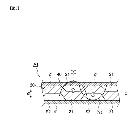
Next, the frame 20 will be described. Fig. 5 is a partial cross-sectional view
showing the fuel cell Al according to the first embodiment of the present
invention, in
the form of a cross section taken along the I-I line indicated in Fig. 4. Each
arrow
shown in Fig. 5 indicates a differential pressure, code (X) indicates a
bending moment
on the frame 20 generated when the pressure of the oxygen-containing gas is
higher
than that of the hydrogen-containing gas, and code (Y) indicates a bending
moment on
the frame 20 generated when the pressure of the hydrogen-containing gas is
higher than
that of the oxygen-containing gas.
[0022]
The membrane electrode assembly 30 is formed integrally with the frame 20 by
injection molding, for example. In this embodiment, the frame 20 is formed
into a
horizontally long rectangle in a front view seen in the stacking direction a
of the fuel
cell Al. Meanwhile, the frame 20 is formed into a substantially uniform plate
thickness and the membrane electrode assembly 30 is located at a central part
of the
frame 20 in the vertical and horizontal directions.
[0023]
The diffuser units D are respectively formed between the frame 20 and each of
the separators 40, 41, i.e., on an anode side and a cathode side (two surface
sides) of the
frame 20. To be more precise, multiple projections 21 formed into the same
truncated
cone shape of the same size are formed integrally with the frame 20 at given
intervals.
Here, a ratio between a height from a bottom surface (a base portion) to an
upper base
CA 02812907 2013-03-27
6
(an upper portion) and a width dimension of the bottom surface of each
projection 21
may be set as appropriate.
[0024]
The projections 21 make the frame 20 and each of the separators 40, 41
opposed to the frame 20 away from each other in the direction of a as shown in
Fig. 5.
In the meantime, hydrogen-containing gas flow paths Si and oxygen-containing
gas
flow paths S2 are formed by arranging the multiple projections 21 at given
intervals on
each of the diffuser units D. The hydrogen-containing gas flow paths Si and
the
oxygen-containing gas flow paths S2 will be hereinafter simply referred to as
the "gas
flow paths Sl, S2".
[0025]
In this embodiment, the projections 21 on the anode side (the one surface
side)
of the frame 20 and the projections 21 on the cathode side (the other surface
side) of the
frame 20 are arranged asymmetrically with respect to the central axis C of the
frame 20
in the stacking direction a of the fuel cell Al (the center of the frame 20 in
the direction
of a). That is to say, the projections 21 are arranged in such a manner that
the gas flow
paths Si and the gas flow paths S2 are formed into asymmetrical shapes with
respect to
the frame 20 in the stacking direction a of the fuel cell Al.
[0026]
In this embodiment, as shown in Fig. 5, the projections 21 on the cathode side
(the other surface side) are arranged opposite the gas flow paths Si on the
anode side
(the one surface side), and the projections 21 on the anode side (the one
surface side)
are arranged opposite the gas flow paths S2 on the cathode side (the other
surface side).
In other words, the projections 21 in the respective flow regions for the
hydrogen-containing gas and the oxygen-containing gas are arranged in such a
manner
as not to be opposed to each other.
[0027]
Each of the separators 40, 41 is formed by pressing a metal plate made of
stainless steel or the like. As shown in Figs. 3, 4, a central portion of each
separator
opposed to the membrane electrode assembly 30 is formed into a bumpy shape, in
CA 02812907 2013-03-27
(
7
which each bump is continuous in a direction p. In addition, manifold holes H1
to 116
having the same shapes and the same sizes as the corresponding manifold holes
H1 to
116 in the frame 20 are formed at both lateral sides of the central portion in
such a
manner as to be opposed to the corresponding manifold holes H1 to H6 in the
frame 20.
[0028]
Accordingly, in bumpy portions 40a, 41a of the separators 40, 41 opposed to
the membrane electrode assembly 30, each projecting portion is in contact with
the
membrane electrode assembly 30 and each receding portion constitutes a flow
path for
the hydrogen-containing gas (or the oxygen-containing gas).
[0029]
According to this embodiment, portions where stresses are generated due to
differential pressures are dispersed in the in-plane direction of the frame
20. In particular,
as shown in Fig. 5, a stress is generated due to the bending moment X at a
position where
the differential pressure toward the separator 40 from the separator 41 is
generated (a
portion indicated by the up arrow in Fig. 5). Similarly, a stress is generated
due to the
bending moment Y at a position where the differential pressure toward the
separator 41
from the separator 40 is generated (a portion indicated by the down arrow in
Fig. 5). Thus,
the bending moment X is displaced with respect to the bending moment Y in the
in-plane
direction. Accordingly, the portions where the stresses are generated due to
differential
pressures are dispersed in the in-plane direction of the frame 20. Thus, the
stress amplitude
can be reduced. In addition, the structural fatigue resistance can be
increased without
reducing a cross-sectional area for the flow of a reaction gas. Moreover, the
section
modulus of each stress-generating portion can be increased by partially
increasing the plate
thickness of the frame 20.
[0030]
Fig. 6 is a partial cross-sectional view showing a cross section of part of a
fuel
cell according to a second embodiment of the present invention. Each arrow
shown in
Fig. 6 indicates a differential pressure, code (X) indicates a bending moment
generated
on a frame 20A when the pressure of the oxygen-containing gas is higher than
that of
CA 02812907 2013-03-27
7a
the hydrogen-containing gas, and code (Y) indicates a bending moment on the
frame
20A generated when the pressure of the hydrogen-containing gas is higher than
that of
the oxygen-containing gas.
[0031]
A fuel cell A2 according to the second embodiment of the present invention
has different intervals of arrangement of the projections 21 from those in the
fuel cell
Al of the first embodiment.
[0032]
Specifically, the intervals of arrangement of the projections 21 in a fuel
cell A2
CA 02812907 2013-03-27
8
are wider than the intervals of arrangement of the projections 21 in the fuel
cell Al. In
other words, each of the gas flow paths Si, S2 is formed to have a width
dimension of a
dimension W1 which is wider than each interval of arrangement of the
projections 21 in
the fuel cell Al. Meanwhile, an interval between a base portion 21a of a
certain
projection 21 on the one surface side of the frame 20A and a corner portion
21b of the
corresponding projection 21 on the other surface side thereof is set to a
dimension W2.
Here, the dimension W2 may be set in consideration of a factor such as the
bending
moment to be generated.
[0033]
According to this embodiment, the dimension W2 representing the interval
between the certain projection 21 on the one surface side and the
corresponding
projection 21 on the other surface side can be reduced. Thus, it is possible
to reduce a
stress generating on the frame 20A at a position between each projection 21 on
the one
surface side and the corresponding projection 21 on the other surface side.
[0034]
Fig. 7(A) is a partial cross-sectional view showing a cross section of part of
a
fuel cell according to a third embodiment of the present invention, and Fig.
7(B) is a
partial cross-sectional view showing a cross section of part of a fuel cell
according to a
fourth embodiment of the present invention. Each arrow shown in Fig. 7
indicates a
differential pressure, code (X) indicates a bending moment generated on a
frame 20B
when the pressure of the oxygen-containing gas is higher than that of the
hydrogen-containing gas, and code (Y) indicates a bending moment on the frame
20B
generated when the pressure of the hydrogen-containing gas is higher than that
of the
oxygen-containing gas.
[0035]
A fuel cell A3 according to the third embodiment of the present invention
shown in Fig. 7(A) is different from the fuel cells Al, A2 in that projections
40b, 41b
equivalent to the projections 21 are formed integrally with a pair of
separators 40A and
41A.
[0036]
,
., CA 02812907 2013-03-27
9
The frame 20B shown in Figs. 7(A), 7(B) is formed integrally with the
membrane electrode assembly 30 by injection molding, for example. Meanwhile,
in
this embodiment, the frame 20B is formed into a horizontally long rectangle in
a front
view seen in the stacking direction a of the fuel cell A3, and is formed into
a
substantially uniform plate thickness. Moreover, the membrane electrode
assembly 30
is located at the central part of the frame 20B in the vertical and horizontal
directions.
However, no projections are arranged on the membrane electrode assembly 30.
[0037]
The multiple projections 40b are integrally formed in the regions of the
separator 40A corresponding to the diffuser units D. The multiple projections
40b are
formed into the same truncated cone shape of the same size and are arranged at
given
intervals.
[0038]
The multiple projections 41b are integrally formed in the regions of the
separator 41A corresponding to the diffuser units D. The multiple projections
41b are
formed into the same truncated cone shape of the same size and are arranged at
given
intervals.
[0039]
In this embodiment, the projections 40b on the anode side (the one surface
side) of the separator 40A and the projections 41b on the cathode side (the
other surface
side) of the separator 41A are arranged asymmetrically with respect to the
frame 20B in
the stacking direction a of the fuel cell A3. That is to say, the projections
40b, 41b are
arranged in such a manner that the gas flow paths Si and the gas flow paths S2
are
formed into asymmetrical shapes with respect to the frame 20B in the stacking
direction
a of the fuel cell A3.
[0040]
In this embodiment, the projections 41b on the cathode side (the other surface
side) are arranged opposite the gas flow paths Si on the anode side (the one
surface
side), and the projections 40b on the anode side (the one surface side) are
arranged
opposite the gas flow paths S2 on the cathode side (the other surface side).
CA 02812907 2013-03-27
[0041]
According to this embodiment, it is possible to displace positions where
stresses are generated and distributions of the stresses in the frame 20B when
differential pressures are generated. Thus, the stress amplitude can be
reduced. In
addition, the structural fatigue resistance can be increased without reducing
a
cross-sectional area for the flow of a reaction gas.
[0042]
A fuel cell A4 according to the fourth embodiment of the present invention
shown in Fig. 7(B) has different intervals of arrangement of the projections
40b, 41b
from those in the fuel cell A3.
[0043]
Specifically, the intervals of arrangement of the projections 40b, 41b in the
fuel
cell A4 are set wider than those in the fuel cell A3. In other words, the gas
flow paths
Si, S2 in the fuel cell A4 are formed to have wider dimensions than those of
the gas
flow paths Si, S2 in the fuel cell A3. An interval between a base portion of a
certain
projection 40b on the one surface side of the frame 20B and a corner portion
of the
corresponding projection 41b on the other surface side thereof is set to a
dimension W2.
[0044]
Here, as similar to the case of the fuel cell A2, the dimension W2 may be set
in
consideration of a factor such as the bending moment to be generated.
[0045]
According to this embodiment, it is possible to displace positions where
stresses are generated and distributions of the stresses in the frame 20B when
differential pressures are generated. Thus, the stress amplitude can be
reduced. In
addition, the structural fatigue resistance can be increased without reducing
a
cross-sectional area for the flow of a reaction gas.
[0046]
Fig. 8 is a partial cross-sectional view showing a cross section of part of a
fuel
cell according to a fifth embodiment of the present invention. Each arrow
shown in
Fig. 8 indicates a differential pressure, code (X) indicates a bending moment
generated
CA 02812907 2013-03-27
11
on a frame 20C when the pressure of the oxygen-containing gas is higher than
that of
the hydrogen-containing gas, and code (Y) indicates a bending moment on the
frame
20C generated when the pressure of the hydrogen-containing gas is higher than
that of
the oxygen-containing gas. Note that constituents equivalent to those
explained in any
of the above-described embodiments will be denoted by the same reference
numerals
and duplicate explanation will be omitted.
[0047]
In a fuel cell A5 according to the fifth embodiment of the present invention,
the
membrane electrode assembly 30 having the frame 20C formed therearound is
sandwiched between components equivalent to the separator 41 shown in Fig. 6
and the
separator 40A shown in Fig. 7(A). Thus, the power generation unit G (not shown
in
Fig. 8) is formed in a region opposed to the membrane electrode assembly 30.
[0048]
The frame 20C is formed integrally with the membrane electrode assembly 30
by injection molding, for example. In this embodiment, the frame 20C is formed
into
a horizontally long rectangle in a front view seen in the stacking direction a
of the fuel
cell A5. The frame 20C is formed into a substantially uniform plate thickness
and the
membrane electrode assembly 30 is located at a central part thereof.
[0049]
In this frame 20C, the multiple projections 21 having the same truncated cone
shape of the same size are arranged only on the cathode side of each diffuser
unit D
while the anode side thereof is formed into a flat surface.
[0050]
In this embodiment, the projections 40b on the anode side (the one surface
side) of the separator 40A and the projections 21 on the cathode side (the
other surface
side) of the frame 20C are arranged asymmetrically with respect to the central
axis C of
the frame 20C in the stacking direction a of the fuel cell AS. That is to say,
the
projections 40b, 21 are arranged in such a manner that the gas flow paths Si
and the gas
flow paths S2 are formed into asymmetrical shapes with respect to the frame
20C in the
stacking direction a of the fuel cell A5.
CA 02812907 2013-03-27
12
[0051]
In this embodiment, the projections 40b of the separator 40A are arranged in
positions opposed to the gas flow paths S2, which are formed by the
projections 21 of
the frame 20C and the separator 41.
[0052]
According to this embodiment, it is possible to displace positions where
stresses are generated and distributions of the stresses in the frame 20C when
differential pressures are generated. Thus, the stress amplitude can be
reduced. In
addition, the structural fatigue resistance can be increased without reducing
a
cross-sectional area for the flow of a reaction gas. Moreover, the section
modulus of
each stress-generating portion can be increased by partially increasing the
plate
thickness of the frame 20C.
[0053]
Fig. 9 is a partial cross-sectional view showing a cross section of part of a
fuel
cell according to a sixth embodiment of the present invention. Each arrow
shown in
Fig. 9 indicates a differential pressure, code (X) indicates a bending moment
generated
on the frame 20B when the pressure of the oxygen-containing gas is higher than
that of
the hydrogen-containing gas, and code (Y) indicates a bending moment on the
frame
20B generated when the pressure of the hydrogen-containing gas is higher than
that of
the oxygen-containing gas. Note that constituents equivalent to those
explained in the
above-described embodiments will be denoted by the same reference numerals and
duplicate explanation will be omitted.
[0054]
A fuel cell A6 according to the sixth embodiment of the present invention is
designed to sandwich the membrane electrode assembly 30 (not shown in Fig. 9),
which
has a component equivalent to the frame 20B shown in Figs. 7(A), 7(B) formed
therearound, between components equivalent to the separator 40B and the
separator
41A shown in Fig. 7(B).
[0055]
Multiple projections 40c are integrally formed in regions of the separator 40B
CA 02812907 2013-03-27
13
corresponding to the diffuser units D.
[0056]
The multiple projections 40c having the same truncated cone shape of the same
size are arranged at given intervals. Here, the area of a contact surface 40c'
of each
projection 40c in contact with the frame 20B is increased as compared to that
of the
projection 40b (41b).
[0057]
In this embodiment, the projections 40c of the separator 40B are arranged
opposite the projections 41b of the separator 41A.
[0058]
In this embodiment, the projections 40c on the anode side (the one surface
side) of the separator 40B and the projections 41b on the cathode side (the
other surface
side) of the separator 41A are arranged asymmetrically with respect to the
frame 20B in
the stacking direction a of the fuel cell A6. That is to say, the projections
40c, 41b are
arranged in such a manner that the gas flow paths Si and the gas flow paths S2
are
formed into asymmetrical shapes with respect to the frame 20B in the stacking
direction
a of the fuel cell A6.
[0059]
According to this embodiment, it is possible to displace positions where
stresses are generated and distributions of the stresses in the frame 20B when
differential pressures are generated. Thus, the stress amplitude can be
reduced. In
addition, the structural fatigue resistance can be increased without reducing
a
cross-sectional area for the flow of a reaction gas.
[0060]
Fig. 10 is a partial cross-sectional view showing a cross section of part of a
fuel
cell according to a seventh embodiment of the present invention. Each arrow
shown in
Fig. 10 indicates a differential pressure, code (X) indicates a bending moment
generated
on a frame 20D when the pressure of the oxygen-containing gas is higher than
that of
the hydrogen-containing gas, and code (Y) indicates a bending moment on the
frame
20D generated when the pressure of the hydrogen-containing gas is higher than
that of
CA 02812907 2013-03-27
14
the oxygen-containing gas. Note that constituents equivalent to those
explained in the
above-described embodiments will be denoted by the same reference numerals and
duplicate explanation will be omitted.
[0061]
A fuel cell A7 according to the seventh embodiment of the present invention is
designed to sandwich the membrane electrode assembly 30 (not shown in Fig.
10),
which has the frame 20D formed therearound, between components equivalent to
the
pair of separators 40, 41 shown in Fig. 6
[0062]
The frame 20D is formed integrally with the membrane electrode assembly 30
by injection molding, for example. In this embodiment, the frame 20D is formed
into
a horizontally long rectangle in a front view seen in the stacking direction a
of the fuel
cell A7, and is formed into a substantially uniform plate thickness. In
addition, the
membrane electrode assembly 30 (not shown) is located at a central part of the
frame
20D.
[0063]
The frame 20D has a structure in which multiple projections 22 are arranged on
a surface on the anode side of the frame 20D and multiple projections 23 are
arranged
on a surface on the cathode side thereof, the projections 22, 23 having
different sizes.
Each of the projections 22, 23 is formed into a truncated cone shape. The area
of a
contact surface 22a of each projection 22 with the separator 40 is made larger
than the
area of a contact surface 23a of each projection 23 with the separator 41.
Moreover,
each projection 22 and the corresponding projection 23 are arranged opposed to
each
other.
[0064]
In this embodiment, the projections 22 on the anode side (the one surface
side)
of the frame 20D and the projections 23 on the cathode side (the other surface
side) of
the frame 20D are arranged asymmetrically with respect to the central axis C
of the
frame 20D in the stacking direction a of the fuel cell A7. That is to say, the
projections 22, 23 are arranged in such a manner that the gas flow paths Si
and the gas
CA 02812907 2014-06-12
flow paths S2 are formed into asymmetrical shapes with respect to the frame
20D in the
stacking direction a of the fuel cell A7. Here, an interval between base
portions of the
adjacent projections 23 is set to a dimension L.
[0065]
According to this embodiment, it is possible to displace positions where
stresses are generated and distributions of the stresses in the frame 20D when
differential pressures are generated. Thus, the stress amplitude can be
reduced. In
addition, the structural fatigue resistance can be increased without reducing
a
cross-sectional area for the flow of a reaction gas. Moreover, the section
modulus of
each stress-generating portion can be increased by partially increasing the
plate
thickness of the frame 20D.
[0066]
It is to be noted that the present invention is not limited only to the
above-described embodiments but the following modifications can also be
embodied.
[0067]
The above-described embodiments show the projections in the truncated cone
shapes as examples. However, columnar shapes, prismatic shapes, elliptic
cylindrical
shapes, and other publicly known shapes may be employed as the shapes of the
projections.
[0068]
The configuration described in each of the embodiments is not applicable only
to the relevant embodiment. The configuration described in one of the
embodiments
may be applied, with or without modifications, to any other embodiments. In
addition,
the configurations may be arbitrarily combined.
[0069]
[0070]
While the contents of the present invention have been described based on the
embodiments, it is obvious to those skilled in the art that the present
invention is not
CA 02812907 2013-03-27
16
limited only to the descriptions herein but various modifications and
improvements can
be made thereto.
INDUSTRIAL APPLICABILITY
[0071]
According to the present invention, it is possible to displace positions where
stresses are generated and distributions of the stresses in the frame body
when
differential pressures are generated. Thus, the structural fatigue resistance
can be
increased without reducing a cross-sectional area for the flow of a reaction
gas.
REFERENCE SIGNS LIST
[0072]
20, 20A, 20B, 20C, 20D frame body (frame)
21, 22, 23, 40b, 41b, 40c projection
30 membrane electrode assembly
40, 41, 40A, 40B separator
Al to A7 fuel cell
D communication region (diffuser unit)
S1, S2 gas flow path