Note: Descriptions are shown in the official language in which they were submitted.
CA 02812967 2013-03-18
WO 2012/040267 PCT/US2011/052461
METHOD AND APPARATUS FOR DYNAMIC, VARIABLE-
PRESSURE, CUSTOMIZABLE, MEMBRANE-BASED WATER
TREATMENT FOR USE IN IMPROVED HYDROCARBON
RECOVERY OPERATIONS
BACKGROUND OF INVENTION
Field of the Invention
[0001] Embodiments disclosed herein relate generally to a method and
apparatus for
dynamic, variable-pressure, customizable, membrane-based water treatment for
use
in improved hydrocarbon recovery operations.
Background Art
[0002] Hydrocarbons accumulated within a subterranean hydrocarbon-bearing
formation are recovered or produced therefrom through production wells drilled
into
the subterranean formation. When production of hydrocarbons slows, improved
recovery techniques may be used to force the hydrocarbons out of the
formation.
One of the simplest methods of forcing the hydrocarbons out of the formation
is by
direct injection of fluid into the formation. This enhances production by
displacing
or sweeping hydrocarbons through the formation so that they may be produced
from
production well(s).
[0003] As shown in FIG. 1, a prior art system for recovering hydrocarbons
from a
formation consists of an offshore rig 12 connected to a well 10, which is
completed
in a subterranean hydrocarbon-bearing formation 14. Generally, fluid is
injected
directly into the subterranean hydrocarbon-bearing formation 14 (indicated by
the
down arrow) and forces the hydrocarbons through the formation and out of the
well
(indicated by the up arrow) via a production well, which may be the same or a
different well. One type of such recovery operation uses water (e.g.,
seawater,
produced water) as the injection fluid, which is referred to as a waterflood.
Water is
injected, under pressure, into the formation via injection wells, driving the
hydrocarbons through the formation toward production wells.
[0004] Injection water used in waterflooding for offshore wells is
typically seawater
and/or produced water because of the low-cost availability of seawater and/or
produced water at offshore locations. Another motivation for using produced
water
1
CA 02812967 2013-03-18
WO 2012/040267 PCT/US2011/052461
as an injection water offshore is the difficulty in some locations in
disposing the
produced water offshore. In any case, seawater and produced water are
generally
characterized as saline, having a high ionic content relative to fresh water.
For
example, the fluids are rich in sodium, chloride, sulfate, magnesium,
potassium, and
calcium ions, to name a few. Some ions present in injection water can benefit
hydrocarbon production. For example, certain combinations of cations and
anions,
including IC, Na+, Cl-, Br-, and OH-, can stabilize clay to varying degrees in
a
formation susceptible to clay damage from swelling or particle migration.
[0005] However, it has also been found that certain ions, including
calcium and/or
sulfate, present in the injection water can have harmful effects on the
injection wells
and production wells and can ultimately diminish the amount or quality of the
hydrocarbon product produced from the production wells. Specifically, sulfate
ions
can form salts in situ when contacted with metal cations such as barium and/or
strontium, which may be naturally occurring in the reservoir. Barium and
strontium
sulfate salts are relatively insoluble and readily precipitate out of solution
under
ambient reservoir conditions. Solubility of the salts further decreases as the
injection water is produced to the surface with the hydrocarbons because of
temperature decreases in the production well. The resulting precipitates
accumulate
as barium sulfate scale in the outlying reservoir, at the wellbore of the
hydrocarbon
production wells, and downstream thereof (e.g., in flow lines, gas/liquid
separators,
transportation pipelines, etc). The scale reduces the permeability of the
reservoir
and reduces the diameter of perforations in wellbores, thereby diminishing
hydrocarbon recovery from the hydrocarbon production wells.
[0006] It has also been reported that a significant concentration of
sulfate ions in
injection water promotes reservoir souring. Reservoir souring is an
undesirable
phenomenon whereby reservoirs are initially sweet upon discovery, but turn
sour
during the course of waterflooding and attendant hydrocarbon production from
the
reservoir. Souring contaminates the reservoir with hydrogen sulfide gas or
other
sulfur-containing species and is evidenced by the production of quantities of
hydrogen sulfide gas along with the desired hydrocarbon fluids from the
reservoir
via the hydrocarbon production wells. The hydrogen sulfide gas causes a number
of
undesired consequences at the hydrocarbon production wells and downstream of
the
2
CA 02812967 2013-03-18
WO 2012/040267 PCT/US2011/052461
wells, including excessive degradation and corrosion of the hydrocarbon
production
well metallurgy and associated production equipment, diminished economic value
of
the produced hydrocarbon fluids, an environmental hazard to the surroundings,
and a
health hazard to field personnel.
[0007] The hydrogen sulfide is believed to be produced by an anaerobic
sulfate-
reducing bacteria. The sulfate-reducing bacteria is often indigenous to the
reservoir
and is also commonly present in the injection water. Sulfate ions and organic
carbon
are the primary feed reactants used by the sulfate reducing bacteria to
produce
hydrogen sulfide in situ. The injection water is usually a plentiful source of
sulfate
ions, while formation water is a plentiful source of organic carbon in the
form of
naturally-occurring low molecular weight fatty acids. The sulfate reducing
bacteria
effects reservoir souring by metabolizing the low molecular weight fatty acids
in the
presence of the sulfate ions, thereby reducing the sulfate to hydrogen
sulfide. Stated
alternatively, reservoir souring is a reaction carried out by the sulfate
reducing
bacteria which converts sulfate and organic carbon to hydrogen sulfide and
byproducts.
[0008] A number of strategies have been employed in the prior art for
remediating
reservoir souring with limited effectiveness. These prior art strategies have
primarily been single pronged attacks against either the sulfate reducing
bacteria
itself or against a specific food nutrient of the sulfate reducing bacteria.
For
example, many prior art strategies have focused on killing the sulfate
reducing
bacteria in the injection water or within the reservoir. Conventional methods
for
killing the sulfate reducing bacteria or limiting their growth may include
ultraviolet
light, biocides, and chemicals such as acrolein and nitrates. Other prior art
strategies
for remediating reservoir souring have focused on limiting the availability of
sulfates
or organic carbon to the sulfate reducing bacteria.
[0009] More recently, strategies for remediating reservoir souring have
included the
use of membranes to reduce the concentration of sulfate ions in injection
water. For
example, U.S. Patent No. 4,723,603 shows that specific membranes can
effectively
reduce the concentration of sulfate ions in injection water, thereby
inhibiting sulfate
scale formation. As taught by the prior art, nanofiltration (NF) membranes are
often
preferred to reverse osmosis (RO) membranes because nanofiltration membranes
3
CA 02812967 2013-03-18
WO 2012/040267 PCT/US2011/052461
generally permit a higher passage of sodium chloride compared to reverse
osmosis
membranes. Consequently, nanofiltration membranes are advantageously operable
at substantially lower pressures and operating costs than reverse osmosis
membranes. Furthermore, nanofiltration membranes also maintain the ionic
strength
of the resulting injection water at a relatively high level, which desirably
reduces the
risk of clay instability and correspondingly reduces the risk of water
permeability
loss through the porous substrata of the subterranean formation.
[0010] However, in addition to the problems associated with sulfate ions
being
present in the injection water, it has also been found that the salinity of an
injection
water can have a major impact on the recovery of hydrocarbons during
waterfloods,
with increased recovery resulting from the use of injection water of lower
salinity
than natural seawater but sufficient ionic strength to prevent clay
instability.
Depending on the type of formation, injection fluids having higher salinity
may
cause the reservoir wettability to become more oilwet. This is because the
multivalent cations in the brine, such as Ca+2 and Mg+2, are believed to act
like
bridges between the negatively charged oil and the negatively charged clay
minerals
that typically line the porewalls of the formation. The oil reacts with the
clay
particles to form organo-metallic complexes, which results in the clay surface
being
extremely hydrophobic and oilwet. As the oilwetness of the reservoir rock
increases, hydrocarbons will adsorb onto the surface of the rock and thereby
flow
less easily from the formation, relative to water, which results in less
hydrocarbon
product being produced.
[0011] Lowering the electrolyte content (i.e., lowering the ionic
strength) by lowering
the overall salinity and especially reducing the multivalent cations in a
brine solution
reduces the screening potential of the cations. This results in increased
electrostatic
repulsion between the clay particles and the oil. Once the repulsive forces
exceed
the binding forces via the multivalent cation bridges, the oil particles are
desorbed
from the clay surfaces and the clay surfaces become increasingly waterwet. If,
however, the electrolyte content is reduced too much (i.e., the brine salinity
is too
low), the clay particles may be stripped from the porewalls (clay
deflocculation),
which will damage the formation. Thus, although it is desirable to have lower
salinity injection water, it is important that the salinity levels not be too
low.
4
CA 02812967 2013-03-18
WO 2012/040267 PCT/US2011/052461
[0012] Lower salinity water, however, is not often available at a well
site. Lower
salinity water is typically prepared, for example, by reducing the total ion
concentration of higher salinity water using membrane separation technology
(e.g.,
reverse osmosis). In known seawater desalination plants operating according to
the
reverse osmosis process, the seawater to be desalinated is subjected to a
separation
process by means of a semi-peimeable membrane. Such a membrane is understood
to be a selective membrane, which is permeable to a high degree to the water
molecules, but only to a very low extent to the salt ions dissolved therein.
[0013] Membrane separation techniques used in the preparation of low
salinity
injection water use reverse osmosis (RO) membrane elements. Membrane
separation techniques used in the preparation of low sulfate injection water
use
nanofiltration (NF) membrane elements. The RO and NF processes use hydraulic
pressure to produce lower salinity water from feed water through a
semipermeable
membrane. Depending on the membrane type, pressure and water conditions, an
amount of salt also passes across the membrane, but the overall salinity of
the
product water is less than that of the feed water. Current RO technology can
be used
for desalinating both seawater and brackish water. The membranes used in the
RO
process are generally either made from polyamides or from cellulose sources.
[0014] The water to be treated is typically pretreated using media
filtration,
microfiltration, or ultrafiltration methods, which are known to separate
solids/particulates from the water based on their size. The water is then fed
to the
reverse osmosis and/or nanofiltration vessel using a high-pressure pump. The
required pressure from the high-pressure pump is a function of the osmotic
pressure,
the temperature, the flux (i.e., the rate at which the water passes through a
unit area
of the membrane), and the volume of the feed water to be produced with a
specific
membrane area. The product water (i.e., the permeate) is discharged from the
membrane module by way of a permeate conduit. A concentrate conduit serves for
discharging concentrated ionic water.
[0015] The operating costs for both systems (i.e., reverse osmosis and
nanofiltration)
are primarily determined by the energy to be applied. The greatest energy
consumer
is the drive of the high-pressure pump, which forces the seawater to be
treated
through the semi-peimeable membranes of the membrane module. The driving
CA 02812967 2015-08-21
54635-55
force for permeation for membrane separation is the net pressure across the
membrane (which
is defined as the feed pressure minus the permeate or back pressure) less the
difference
between the osmotic pressure of the feed and the osmotic pressure of the
permeate. Because
nanofiltration membranes allow high salt passage for monovalent ions, the
osmotic pressure
of the permeate is significant, which allows the membranes to partially
desalinate the seawater
while operating at pressure below the actual osmotic pressure of the feed.
[0016] Energy saving measures are usually employed, especially in
connection with
reverse osmosis plants operating on the large scale, in order to keep the
costs of desalination
as low as possible. However, the energy required to drive the high-pressure
pump varies
based on what type of membrane technology is being used because different
membranes
require different pressures and, therefore, different pumps. For example,
reverse osmosis is a
high pressure process that requires a high-pressure pump that will provide,
for example,
approximately 800-1200 psi (-55-82 bar) of pressure to the seawater, whereas
nanofiltration
is a low to moderately high pressure process that requires a pump that will
provide, for
example, approximately 50-450 psi (-3-31 bar) of pressure to the seawater.
[0017] A number of efforts have been made in the prior art to
minimize the cost
associated with operating a membrane system. Most often, a treatment plant
will comprise
several membranes connected in series and/or parallel, wherein all of the
membranes are of a
similar type. For example, a prior art desalination plant will typically
include multiple blocks
(or trains) of reverse osmosis membranes. In such systems, pretreated seawater
is pumped
through the membrane using pressure from a high-pressure pump. These systems,
however,
are typically limited to membranes of a similar kind, because then only one
model of pump is
required, which keeps the cost associated with driving the pump to a minimum.
SUMMARY OF INVENTION
[0018] In one aspect, embodiments disclosed herein relate to a method for
treating
water comprising: intaking water into a treatment block; wherein the treatment
block
comprises: a membrane pressure vessel comprising a membrane element, wherein
the
treatment block is configured such that the intake water is fed through the
membrane element
6
CA 02812967 2015-08-21
54635-55
of the membrane pressure vessel, wherein the membrane element of the membrane
pressure
vessel is capable of being replaced by a different membrane element having a
different
pressure requirement, feeding the intake water through the membrane pressure
vessel at a
custom pressure based on the membrane element of the membrane pressure vessel,
wherein
the custom pressure is capable of being produced by a variable speed high-
pressure pump and
a turbobooster coupled to the variable speed high-pressure pump, selectively
bypassing the
turbobooster when the custom pressure needed for the membrane element can be
produced by
the variable speed high-pressure pump; selectively bypassing the turbobooster
when the
different custom pressure needed for the different membrane element can be
produced by the
variable speed high-pressure pump; separating the intake water into at least
an aqueous
permeate stream and a concentrate reject stream; and outputting the aqueous
permeate stream
and the concentrate reject stream.
[0019] In another aspect, embodiments disclosed herein relate to a
membrane-based
water treatment system, comprising: a water intake system that intakes water;
a treatment
block, comprising: a variable speed high-pressure pump; and a membrane
pressure vessel
comprising a membrane element, wherein the variable speed high-pressure pump
feeds the
intake water through the membrane pressure vessel at a custom pressure based
on the
membrane elements comprised in the membrane pressure vessel, wherein the
membrane
element of the membrane pressure vessel is capable of being replaced by a
different
membrane element having a different pressure requirement, and wherein the
variable speed
high-pressure pump is capable of feeding the intake water through the membrane
pressure
vessel at a different custom pressure based on the different membrane element,
wherein the
membrane pressure vessel separates the intake water into at least an aqueous
permeate stream
and a concentrate reject stream; an energy recovery system adapted to recover
energy from
the concentrate reject stream, wherein the energy recovery system comprises: a
turbobooster
coupled to the variable speed high-pressure pump, wherein the energy recovered
from the
concentrate reject stream is selectively used in the production of the custom
pressure at which
the intake water is fed through the membrane pressure vessel when the custom
pressure
needed for the membrane element exceeds the pressure that can be produced by
the variable
speed high-pressure pump, and wherein the energy recovered from the
concentrate reject
7
CA 02812967 2015-08-21
54635-55
stream is selectively used in the production of the custom pressure at which
the intake water is
fed through the membrane pressure vessel when the different custom pressure
needed for the
different membrane element exceeds the pressure that can be produced by the
variable speed
high-pressure pump, and an output system that respectively outputs the aqueous
permeate
stream and the concentrate reject stream.
[0020] Other aspects and advantages of the invention will be apparent
from the
following description and the appended claims.
BRIEF DESCRIPTION OF DRAWINGS
[0021] FIG. 1 shows a prior art offshore production well.
[0022] FIG. 2 shows a seawater treatment process according to one or more
embodiments of the present invention.
[0023] FIG. 3A is a diagram of a seawater treatment unit on a vessel
according to one
or more embodiments of the present invention.
[0024] FIG. 3B is a diagram of a seawater treatment unit on an off-
shore rig according
to one or more embodiments of the present invention.
[0025] FIG. 3C is a diagram of a rig, a vessel, and a seawater
treatment unit on the
seafloor according to one or more embodiments of the present invention.
7a
CA 02812967 2013-03-18
WO 2012/040267 PCT/US2011/052461
[0026] FIG. 4A shows another seawater treatment process according to one
or more
embodiments of the present invention.
[0027] FIG. 4B shows a treatment block according to one or more
embodiments of
the present invention.
[0028] FIG. 4C shows a spiral wound membrane element according to one or
more
embodiments of the present invention.
[0029] FIG. 4D shows a schematic for a hollow fine fiber membrane element
according to one or more embodiments of the present invention.
[0030] FIG. 5 shows an improved oil recovery system according to one or
more
embodiments of the present invention.
[0031] FIG. 6A shows a configuration for a system or method according to
one or
more embodiments of the present invention.
[0032] FIG. 6B shows a configuration for a system or method according to
one or
more embodiments of the present invention.
[0033] FIG. 7 shows a configuration for a system or method according to
one or more
embodiments of the present invention.
DETAILED DESCRIPTION
[0034] One or more embodiments of the present invention will be described
below
with reference to the figures. In one aspect, embodiments disclosed herein
relate to
systems and methods for treating seawater using membrane technology to prepare
an
aqueous fluid having specific ions removed therefrom. In another aspect,
embodiments disclosed herein relate to creating a customized pressure based on
the
type of membranes used in a water treatment process. In yet another aspect,
embodiments disclosed herein relate to the treatment of seawater using a
treatment
system to produce an aqueous fluid which has specifically tailored properties
and
which is capable of being used as an injection fluid to be used in improved
oil
recovery operations. In yet another aspect, embodiments disclosed herein
relate to
blending treated fluids which have specifically tailored properties. In yet
another
8
CA 02812967 2013-03-18
WO 2012/040267 PCT/US2011/052461
aspect, embodiments disclosed herein relate specifically to improved oil
recovery
operations in offshore wells.
[0035] Seawater Treatment
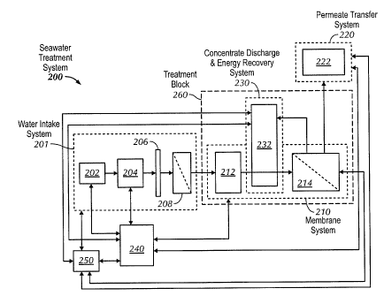
[0036] Referring to FIGS. 2 and 3A-C, a seawater treatment system
according to one
or more embodiments is shown. As shown in FIG. 2, the present invention
provides
a single-pump, single-pass seawater treatment system 200 that may include a
water
intake system 201, a membrane system 210, permeate transfer and treatment
system
220, a concentrate discharge and energy recovery system 230, a control system
240,
and a power source 290. Water intake system 201 may include water intake 202,
water intake pump 204, pre-filter 206, and membrane/media-filter 208; membrane
system 210 may include a variable speed high-pressure pump 212 and either a
reverse osmosis and/or nanofiltration membrane 214; the concentrate discharge
and
energy recovery system 230 may include a turbobooster, turbocharger, or other
energy recovery device 232 and a plurality of discharge ports; and permeate
transfer
and treatment system 220 may include a permeate transfer pump 222. As shown in
FIGS. 3A-C, the seawater treatment system 200 may be provided on a vessel 300,
on
a rig 312, and/or on the seafloor 316.
[0037] Additionally, according to one or more embodiments, treatment
block 260
may be used to describe the system that includes, for example, both membrane
system 210 and concentrate discharge and energy recovery system 230.
[0038] The treatment block 260 is in communication with the water intake
system
201 and the pellneate transfer and treatment system 220. Both the control
system
240 and the power source 290 are in communication with one another, as well as
in
communication with the water intake system 201, the pelineate transfer and
treatment system 220, and treatment block 260 (i.e., membrane system 210 and
concentrate discharge and energy recovery system 230). As used herein, the
tenns
"communicate" or "communication" mean to mechanically, electrically, or
otherwise contact, couple, or connect by direct, indirect, or operational
means.
[0039] Within the water intake system 201, water intake pump 204 pumps
the intake
water through pre-filter 206 to remove any large contaminants (e.g., sand,
rocks,
plants, debris, etc.) and then through a low pressure membrane or media filter
208 to
9
CA 02812967 2013-03-18
WO 2012/040267 PCT/US2011/052461
remove large molecules (e.g., suspended solids, colloids, macromolecules,
bacteria,
oils, particulate matter, proteins, high molecular weight solutes, etc.). One
of
ordinary skill in the art will appreciate that depending on the specifications
of the
equipment and the type and density of particulate matter to be removed,
various
types of filters, including for example, sand or media filters, cartridge
filters, ultra
filters, and/or micro filters may be used.
[0040] Furthermore, the water intake system 201 may include one or more
variable-
depth extension members capable of extending into the body of water so as to
intake
water from a desired depth. Additionally, the extension member may include one
or
more intake screens designed to help prevent fouling of the intakes by marine
life or
other particles. One of ordinary skill in the art will appreciate that
depending on the
intended body of water from which water is being taken, other equipment may
also
be employed.
[0041] After passing through water intake system 201, the filtered
seawater is
provided to treatment block 260 wherein a variable speed high-pressure pump
212
pushes the filtered seawater through to membrane 214, whereby a concentrate is
created on the high pressure side of the membrane 214 and a permeate stream is
created on the low pressure side of the membrane 214.
[0042] The permeate stream may comprise water that has specific ions
and/or
molecules removed therefrom, for example, the permeate stream may have lower
sulfate ion content and/or lower salinity compared to the filtered seawater
produced
from water intake system 201. The permeate stream may then be transferred, for
example, from vessel 300 to rig 312, from seafloor 316 to rig 312, and/or from
rig
312 to well 310, through permeate transfer and treatment system 220.
[0043] Permeate streams from various treatment blocks 260 may be blended.
Each
treatment block can use the same or a different type of RO or NF membrane
requiring its respective pressure from the high-pressure pump 212. Blending
the
various permeate streams from each treatment block can then provide a very
specific
composition of mono- and divalent ions as a function of optimum reservoir
performance.
CA 02812967 2013-03-18
WO 2012/040267 PCT/US2011/052461
[0044] In a different embodiment, a permeate stream from a treatment
block 260 can
be further treated using forward osmosis (FO) to further refine the ionic
balance as a
function of achieving optimum reservoir performance.
[0045] In another embodiment, instead of seawater as the source of water
through
intake system 201, brackish water could be the feed water, thereby allowing
the
flexibility to switch between brackish water and seawater treatment.
[0046] The permeate transfer and treatment system 220 may be capable of
transferring the permeate produced to a permeate delivery means comprising a
pipeline in communication with the permeate transfer and treatment system 220.
The pipe line may transfer the permeate, for example, from vessel 300 to rig
312,
from seafloor 316 to rig 312, and/or from rig 312 to well 310. The permeate
transfer
and treatment system 220 may also be capable of treating the permeate produced
either prior to, during, or after the permeate is transferred. Treatment of
the
permeate may include "post-treatment", for example, chemical addition (e.g.,
in line
chemical injection) and/or deaeration (e.g., in a vacuum system).
[0047] The concentrate created on the high pressure side of the membrane
214
comprises the ions and/or molecules removed by membrane 214. The concentrate
is
then disposed of, for example, through a plurality of concentrate discharge
ports
within the concentrate discharge and energy recovery system 230. However,
before
the concentrate is disposed of, a turbobooster (or other energy recovery
device) 232
is used to capture the energy possessed by the concentrate and return such
energy to
the variable speed high-pressure pump 212. By doing so, the operating costs
the
system can be reduced, for example, by 40-50%, by recovering part of the
hydraulic
energy contained in the concentrate line (i.e., the reject water line).
[0048] More specifically, as the untreated water is pumped across the
membrane, a
pressure differential is created and concentrated salt water is discharged via
the
concentrate line. This results in the concentrate line retaining considerable
hydraulic
energy. A volumetric pump installed in the concentrate line then operates as a
turbine to reduce the pressure in the concentrate line and recover the excess
energy.
The recovered energy is then used to drive the high-pressure pump, which
reduces
the amount of energy that must be expended for driving the high-pressure pump.
11
CA 02812967 2013-03-18
WO 2012/040267 PCT/US2011/052461
[0049] Furthermore, the concentrate may be diluted or otherwise treated
prior to
disposal. For example, in one or more embodiments, the concentrate discharge
and
energy recovery system 230 may be configured to increase the mixing of the
concentrate discharged into the surrounding body of water. The plurality of
discharge ports of the concentrate discharge and energy recovery system 230
may be
physically located above or below the water line 318 of the vessel 300 and/or
the rig
312. Also, the discharge ports may be disposed on a variable-depth extension
member that can be positioned so as to promote dispersion of the concentrate
into
the body of water.
[0050] In one or more embodiments, the effluent from membrane 214 (either
the
permeate stream or the concentrate) may take one or more subsequent passes
through membrane 214.
[0051] According to one or more embodiments of the present invention, a
separate
power source may provide power to each of the water intake system 201,
permeate
transfer and treatment system 220, treatment block 260 (i.e., membrane system
210
concentrate discharge and energy recovery system 230), and propulsion device
302.
For example, each of the water intake pump 204, variable speed high-pressure
pump
212, and permeate transfer pump 222 may be in communication with a separate
power source.
[0052] According to one or more embodiments, the seawater treatment
system 200
may be land-based or provided on a vessel. Where the seawater treatment system
200 is provided on a vessel 300, vessel 300 may further comprise a propulsion
device 302 in communication with the power source 290. The vessel 300 may be a
self-propelled ship, a moored, towed, pushed or integrated barge, or a
flotilla or fleet
of such vessels. The vessel 300 may be manned or unmanned. The vessel 300 may
be either a single-hull or double-hull vessel.
[0053] Alternatively, in one or more embodiments, one power source may
provide
power to a combination of two or more of the water intake system 201, membrane
system 210, permeate transfer and treatment system 220, concentrate discharge
and
energy recovery system 230, and/or propulsion device 302 where the seawater
treatment system 200 is provided on a vessel 300. For example, electric power
for
12
CA 02812967 2013-03-18
WO 2012/040267 PCT/US2011/052461
the variable speed high-pressure pump 212 may be provided by a generator
driven
by the power source for the vessel's propulsion device, such as a vessel's
main
engine. In such an embodiment, a step-up gear power take off or transmission
would be installed between the main engine and the generator in order to
obtain the
required synchronous speed.
[0054] Further, an additional coupling between the propulsion device and
the main
engine allows the main engine to drive the generator while the vessel is not
under
way. Moreover, an independent power source (not shown), such as a diesel,
steam,
or gas turbine, renewable energy generator, or combinations thereof, may power
the
treatment block 260, the propulsion device 302, or both.
[0055] In other embodiments, the power source for seawater treatment
system 200
may be dedicated solely to the seawater treatment system 200.
[0056] In yet other embodiments, the plurality of concentrate discharge
ports of the
concentrate discharge and energy recovery system 230 may act as an auxiliary
propulsion device for the vessel 300 or act as the sole propulsion device for
the
vessel 300. Some or all of the concentrate may be passed to propulsion
thrusters to
provide idling or emergency propulsion.
[0057] In other embodiments, the power source 290 may comprise electricity
producing windmills and/or water propellers that harness the flow of the air
and/or
water to generate power for the seawater treatment system 200 and/or the
operation
of the vessel 300 and/or rig 312.
[0058] For embodiments where the seawater treatment system 200 is on a
vessel 300,
the water intake system 201 may be capable of taking in seawater from the
water
surrounding the vessel 300 and providing it to the treatment block 260. In
such
embodiments, the water intake 202 of the water intake system 201 may include
one
or more apertures in the hull of the vessel 300 below the water line 318. An
example of a water intake 202 is a sea chest (not shown). Water is taken into
the
vessel 300 through the one or more apertures (i.e. , water intake 202), passed
through
the water intake pump 204, pre-filter 206, ultra filter 208, and supplied to
the
variable speed high-pressure pump 212.
13
CA 02812967 2013-03-18
WO 2012/040267 PCT/US2011/052461
[0059] For embodiments where the seawater treatment system 200 is on an
offshore
rig 312, the water intake system 201 may be capable of taking in seawater from
the
water surrounding the rig 312 and providing the seawater to the treatment
block 260.
In such embodiments, the water intake 202 of the water intake system 201 may
include an intake riser(s), screen(s), and external or submerged pump(s).
[0060] For embodiments where the seawater treatment system 200 is on the
seafloor
316, the water intake system 201 may be capable of taking in seawater from the
water surrounding the seawater treatment system 200 and providing it to the
membrane system 210. In such embodiments, the water intake 202 of the water
intake system 201 may include an intake well or riser, screen(s) and pump(s).
[0061] The membrane system 210 may comprise a variable speed high-pressure
pump
212 and a membrane 214. In one or more embodiments, membrane 214 is an ion
selective membrane, which may selectively prevent or at least reduce hardening
or
scale-forming ions (e.g., divalent ions including sulfate, calcium, and
magnesium
ions) from passing across it, while allowing water and other specific ions
(e.g.,
monovalent ions including sodium, chloride, bicarbonate, and potassium ions)
to
pass across it. The selectivity of the membrane may be a function of the
particular
properties of the membrane, including pore size and charge characteristics of
the
polymeric structure comprising the membrane. For example, a polyamide
membrane, a cellulose acetate membrane, a nano-embedded membrane, and/or other
membrane innovation may be used to selectively prevent or at least reduce
sulfate,
calcium, and magnesium ions from passing across it. In a particular
embodiment,
membrane 214 may reduce up to about 99% of the sulfate ions.
[0062] In one or more embodiments, membrane 214 is a desalting membrane,
which
may lower the total salinity or ionic strength of the filtered seawater by
preventing
or at least reducing ions (e.g., sodium, chloride, calcium, potassium,
sulfate,
bicarbonate, and magnesium ions) from passing across it.
[0063] In one or more embodiments, membrane 214 is a nanofiltration
membrane.
Examples of commercially available nanofiltration membranes suitable for use
in
the treatment process of the present disclosure may include, for example,
FILMTECTm SR90 Series, NF 200 Series, which is available from The Dow
14
CA 02812967 2013-03-18
WO 2012/040267 PCT/US2011/052461
Chemical Company (Minneapolis, MN), or membranes with similar rejection
properties from other membrane manufacturers.
[0064] In one or more embodiments, membrane 214 is a reverse osmosis
membrane.
Examples of commercially available reverse osmosis membranes suitable for use
in
the treatment process of the present disclosure may include, for example,
FILMTECTm SW 30 Series, which is available from The Dow Chemical Company
(Minneapolis, MN), or other membranes with similar rejection properties from
other
membrane manufacturers.
[0065] As shown in FIGS. 4A-B, the seawater treatment system 200 may
include a
membrane system 210 that includes a plurality of membrane pressure vessels
(shown as 214, 216, and 218), which may be arranged in parallel. Although
three
membrane pressure vessels are shown, other embodiments may include more or
less
than three membranes. According to one or more embodiments, each membrane
pressure vessel may include a plurality of membrane elements 250 installed
therein.
Although six elements 250 are shown in each membrane pressure vessel, other
embodiments may include more or less than six elements 250.
[0066] As shown in FIGS. 4B-C, according to one or more embodiments, each
element 250 may comprise, for example, reverse osmosis membrane elements,
nanofiltration membrane elements, or other membrane elements known in the art.
Membrane elements 250 may comprise one of several configurations known in the
art, for example, spiral wound (SW) and/or hollow fine fiber (HFF).
[0067] As shown in FIG. 4C, according to one or more embodiments, elements
250
may comprise spiral wound elements 250. Spiral wound elements 250 may be
constructed from flat sheet membranes 254 and 256 and may include a backing
material 258 to provide mechanical strength. = The membrane material may be
cellulosic (i.e., cellulose acetate membrane) or non-cellulosic (i.e.,
composite
membrane). For cellulose acetate membranes, the two layers may be different
forms
of the same polymer, referred to as "asymmetric." For composite membranes, the
two layers may be completely different polymers, with the porous substrate
often
being polysulfone.
CA 02812967 2013-03-18
WO 2012/040267 PCT/US2011/052461
[0068] In the spiral wound design, the membrane is formed in an envelope
that is
sealed on three sides. A supporting grid, called the product water carrier, is
on the
inside. The envelope is wrapped around a central collecting tube 260, with the
open
side sealed to the tube. Several envelopes, or leaves, are attached with an
open work
spacer material 262 between the leaves. This is the feed/concentrate, or feed-
side
spacer. The leaves are wound around the product water tube 260, forming
spirals if
viewed in cross section. Each end of the unit may be finished with a plastic
molding, called an "anti-telescoping device," and the entire assembly may be
encased in a thin fiberglass shell (not shown). Feed water may flow through
the
spiral over the membrane surfaces, roughly parallel to the product water tube
260.
Product water flows in a spiral path within the envelope to the central
product water
tube 260. A chevron ring (not shown) around the outside of the fiberglass
shell may
force the feed water to flow through the element 250.
[0069] As shown in FIG. 4D, according to one or more embodiments,
elements 250
may comprise hollow fine fiber elements 270. The design of the hollow fine
fiber
elements 270 may include a plurality of hollow fiber membranes 272 being
placed in
a membrane pressure vessel 280. The hollow fine fiber may be a polyaramid or a
blend of cellulose acetates. The membranes 272 may have an outside diameter of
about 100 to about 300 microns and in inside diameter between 50 and about 150
microns. The fibers may be looped in a U-shape, so both ends are imbedded in a
plastic tubesheet 274. The pressurized seawater may be introduced into the
vessel
(indicated by arrow 276) along the outside of the hollow fibers. Under
pressure,
desalted water passes through the walls of the hollow fiber membranes 272 and
flows down the inside of the fiber membranes 272 to a permeate collection tube
278
for collection (as indicated by arrow 282), while the separated concentrate is
removed from the membrane pressure vessel 280 (as indicated by arrow 284).
[0070] According to one or more embodiments, all of the membrane pressure
vessels
in membrane system 210 may comprise elements 250 having only reverse osmosis
membrane elements installed therein. In another embodiment, all of the
membrane
pressure vessels in membrane system 210 may comprise elements 250 having only
nanofiltration membrane elements installed therein. In other embodiments, one
or
more membrane pressure vessel (e.g., membrane pressure vessel 214) may
comprise
16
CA 02812967 2013-03-18
WO 2012/040267 PCT/US2011/052461
elements 250 having either nanofiltration or reverse osmosis membrane elements
installed therein while the remaining membrane pressure vessels (e.g.,
membrane
pressure vessels 216 and 218) comprise elements 250 having only reverse
osmosis
or nanofiltration membrane elements installed therein. While specific examples
of
combinations of membrane pressure vessels and membrane element types are
listed
here, these examples are not intended to be exhaustive and other combinations
may
be used. Those skilled in the art will appreciate other appropriate examples
and
combinations, which are intended to be encompassed by one or more embodiments.
[0071] As shown in FIGS. 3A-C, one or more treatment blocks 260 may be
installed
on the deck 304 of a vessel 300, on the platform 305 of a rig 312, and/or on
the
seafloor 316, depending on the location of the seawater treatment system 200.
Additionally, the one or more treatment blocks may also be installed in other
parts of
the vessel 300 and/or the rig 312, or even on multiple levels of the vessel
300 and/or
the rig 312. For example, each treatment block may be installed in a separate
container. Several containers can be placed on top of each other to optimize
the use
of the deck 304 and/or platform 305 to decrease the time and expense
associated
with construction of the seawater treatment system on the vessel 300 and/or
rig 312.
The one or more treatment blocks may be installed in series or in parallel.
[0072] Within the water intake system 201, water intake pump 204 pumps
the intake
water through pre-filter 206 to remove any large contaminants (e.g., sand,
rocks,
plants, debris, etc.) and then through filter 208 to remove large molecules
(e.g.,
suspended solids, colloids, macromolecules, bacteria, oils, particulate
matter,
proteins, high molecular weight solutes, etc.). After passing through water
intake
system 201, the filtered seawater is provided to treatment block 260 by
variable
speed high-pressure pump 212. Although only one treatment block 260 is shown,
according to one or more embodiments, there may be more than one treatment
block
arranged in series and/or in parallel.
[0073] According to one or more embodiments, within treatment block 260,
there
may be one or more membrane pressure vessels (e.g., 214, 216, and 218). In one
embodiment, the pressurized seawater may be pushed through the first membrane
pressure vessel (e.g., 214) having one or more elements 250 with membrane
elements installed therein, thereby creating a first permeate stream and a
first
17
CA 02812967 2013-03-18
WO 2012/040267 PCT/US2011/052461
concentrate stream. The first permeate stream may comprise water that has
specific
ions removed therefrom, for example, the first permeate stream may have lower
sulfate ion content and/or lower salinity compared to the filtered seawater
produced
from water intake system 201. The first concentrate stream may comprise the
ions
and/or molecules removed by the membrane elements in the first membrane
pressure
vessel (e.g., 214). The first concentrate stream may then be disposed of, for
example, through a plurality of concentrate discharge ports within the
concentrate
discharge and energy recovery system 230. However, before the first
concentrate is
disposed of, turbobooster (or other energy recovery device) 232 may be used to
capture the energy possessed by the first concentrate stream and return such
energy
to the variable speed high-pressure pump 212.
[0074] According to one or more embodiments, this process may continue
for as
many membrane pressure vessels as there are in the treatment block 260.
Additionally, this process may continue for as many treatment blocks 260 as
there
are in the treatment system 200, until a final permeate stream is produced
from a
final membrane pressure vessel. The final permeate stream may then be
transferred,
for example, from vessel 300 to rig 312, from seafloor 316 to rig 312, and/or
from
rig 312 to well 310, through the permeate transfer and treatment system 220.
[0075] In one or more embodiments, the membrane elements installed within
the
membrane pressure vessels (e.g., 214, 216, and 218) are all ion selective
membrane
elements that lower the salinity or ionic strength of the seawater by
selectively
preventing or at least reducing certain ions (e.g., sodium, calcium,
potassium, and
magnesium ions) from passing through the membrane elements, while allowing
water and other specific ions (e.g., sulfate, calcium, magnesium, and
bicarbonate
ions) to be produced for use and/or further treatment. In other embodiments,
the
membranes elements are all ion selective membranes that selectively prevent or
at
least reduce hardening or scale-forming ions (e.g., sulfate, calcium,
magnesium, and
bicarbonate ions) from passing through the membrane elements, while allowing
water and other specific ions (e.g., sodium and potassium ions) to be produced
for
use and/or further treatment.
[0076] In one or more embodiments, the seawater treatment system 200 may
include
multiple treatment blocks 260, wherein the multiple treatment blocks 260 each
18
CA 02812967 2013-03-18
WO 2012/040267 PCT/US2011/052461
comprise different membrane pressure vessels. For example, in one embodiment,
one or more treatment block 260 may include membrane pressure vessels (e.g.,
214,
216, and 218) having membrane elements installed therein wherein the membrane
elements comprise only nanofiltration membrane elements, while one or more
separate treatment block 260 includes membrane pressure vessels (e.g., 214,
216,
and 218) having membrane elements installed therein wherein the membrane
elements comprise only reverse osmosis membrane elements. Additionally, one of
ordinary skill in the art would recognize that the number of treatment blocks
in a
system may vary in one or more embodiments. Further, one of ordinary skill in
the
art in possession of the present disclosure will recognize that the membrane
elements may vary and may be, for example, spirally wound, hollow fiber,
tubular,
plate and frame, or disc-type.
[0077] According to one or more embodiments, the variable speed high-
pressure
pump that operates to push the pretreated water through the treatment block
260 may
comprise any pump suitable to generate the hydraulic pressure necessary to
push the
water through the one or more membrane pressure vessels. However, the pump
discharge pressure must be controlled in order to maintain the designated
permeate
flow and, more importantly, to not exceed the maximum allowed feed pressure
for
the membrane elements being used. This is of particular importance because if
the
maximum allowed feed pressure is exceeded, the membrane element may blow out
and thereby fail prematurely. Because the maximum allowed feed pressure for
nanofiltration elements is typically much greater than the maximum allowed
feed
pressure for reverse osmosis element, conventional membrane systems having
more
than one type of membrane (e.g., nanofiltration and reverse osmosis) typically
require more than one pump (i.e., a pump for each type of membrane).
Conventional systems with nanofiltration membranes installed cannot change to
reverse osmosis membranes due to this pressure differential.
[0078] However, according to one or more embodiments, the treatment block
260
may include a single variable-speed high-pressure pump 212 that provides the
filtered seawater to more than one membrane pressure vessel. Because the
membrane pressure vessels may vary in size and/or may include different types
of
membrane elements, and therefore require varying feed pressures, the high-
pressure
19
CA 02812967 2013-03-18
WO 2012/040267 PCT/US2011/052461
pump 212 must be able to provide an adjustable feed pressure based on the type
of
system being used. For example, pretreated seawater has an osmotic pressure of
about 24, thus, for a nanofiltration membrane, pressurization of at least 20
bar must
be exerted on the feed stream 210, while pressurization of at least 70 bar
must be
exerted for a reverse osmosis membrane. In one or more embodiments, the
variable
speed high-pressure pump may comprise, for example, a positive displacement
pump.
[0079] In a preferred embodiment, the pump may be used to provide
approximately
16,068 m3/d (or 670 m3/hr or 2950 gpm) at varying pressures. Specifically, for
a
seawater reverse osmosis (SWRO) treatment system with an energy recovery
device
(ERD), the lowest needed pressure is about 26.5 bar and the highest needed
pressure
may be about 30.2 bar. For an NF system with no ERD, the lower required
pressure
is about 27 bar while the highest required pressure may be about 39 bar. For a
sulfate reducing nanofiltration (SRNF) system with no ERD, the lowest needed
pressure may be about 14 bar and the highest required pressure may be about 19
bar.
[0080] One or more embodiments of the present invention may also include
variable
frequency drives (VFD) on the high-pressure pump. The VFD are systems that
control the rotational speed of an alternating current (AC) electric motor by
controlling the frequency of the electrical power supplied to the motor. By
employing VFD, the pressures created by the variable speed high-pressure pump
can
also be varied according to the specific needs of the system at any time, for
example,
as a function of operation, membrane type, water quality objectives, and/or
seawater
temperature and salinity.
[0081] However, the flexibility achieved from using variable frequency
drives on the
high-pressure pump is limited. Thus, according to one or more embodiments, it
may
be advantageous to couple the VFD system with an energy recovery system. For
example, as shown in FIGS. 2 and 4A-B, according to one or more embodiments,
energy may be recovered from the concentrate stream using a turbobooster (or
other
energy recovery device) 232. In seawater systems, typically about 55 to 60% of
the
pressurized feed water leaves the system with about 60 bar pressure in the
concentrate stream. This energy can be recovered to decrease the specific
energy
demand of the system. In addition to a turbobooster, energy recovery methods
may
CA 02812967 2013-03-18
WO 2012/040267 PCT/US2011/052461
include pelton wheel, reverse turning turbine, and/or piston type work
exchanger.
The high pressure concentrate is fed into the energy recovery device (e.g.,
the
turbobooster or other energy recovery device) where it produces a rotating
power
output. This may be used to assist the main electric motor in driving the high-
pressure pump. Compared to traditional pump drives, the energy recovery system
represents energy savings up from about 40% to about 50%.
[0082] According to one or more embodiments, the recovered energy may be
used to
drive the variable speed high-pressure pump 212 that pumps the filtered
seawater to
the treatment block 260. In other embodiments, energy recovery may not be
necessary to achieve sufficient pressure for operation of certain membranes,
in
which case the turbobooster may be bypassed.
[0083] When combined with the VFD on the variable speed high-pressure
pump,
turbobooster energy recovery may allow for a high-pressure pump to be adjusted
according to the specific type of membrane elements being used. This is
advantageous because typical high-pressure pumps are not capable of operating
across the full range of pressures required for both nanofiltration and
reverse
osmosis membrane elements. As discussed above, depending on the type of
membrane element being used, the pretreated seawater may need to be
pressurized
to the appropriate pressure that is below the osmotic pressure of the solution
prior to
entry into a membrane. Pretreated seawater has an osmotic pressure of about
24,
thus, for a nanofiltration membrane, pressurization of at least 20 bar (but no
more
than the maximum allowed feed pressure of ¨41 bar) must be exerted on the feed
stream 210, while pressurization of at least 70 bar (but no more than the
maximum
allowed feed pressure of ¨82 bar) must be exerted for a reverse osmosis
membrane.
[0084] Accordingly, one or more embodiments provide a seawater treatment
system
having the flexibility to switch between multiple membrane elements using a
single
high-pressure pump, whereby the seawater can be treated to produce any kind of
water having specifically tailored properties without having to use multiple
high-
pressure pumps and/or having to pass through multiple treatment systems.
[0085] As discussed above, seawater has a high ionic content relative to
fresh water.
For example, seawater is typically rich in ions such as sodium, chloride,
sulfate,
magnesium, potassium, and calcium ions. Seawater typically has a total
dissolved
21
CA 02812967 2013-03-18
WO 2012/040267 PCT/US2011/052461
solids (TDS) content of at least about 30,000 mg/L. According to one or more
embodiments, it is preferred that the permeate stream have a total dissolved
solids
content of less than about 4,000 mg/L, and more preferably from about 2,000 to
about 4,000 mg/L.
[0086] Improved Oil Recovery
[0087] As noted above, improved oil recovery processes commonly inject
water into
a subterranean hydrocarbon-bearing reservoir via one or more injection wells
to
facilitate the recovery of hydrocarbons from the reservoir via one or more
hydrocarbon production wells. The water can be injected into the reservoir as
a
waterflood in a secondary oil recovery process. Alternatively, the water can
be
injected into the reservoir in combination with other components as a miscible
or
immiscible displacement fluid in a tertiary oil recovery process. Water is
also
frequently injected into subterranean oil and/or gas reservoirs to maintain
reservoir
pressure, which facilitates the recovery of hydrocarbons and/or gas from the
reservoir.
[0088] According to one or more embodiments, injection fluids may include
aqueous
solutions (e.g., seawater) that have been treated according to methods
disclosed
above. In a particular embodiment, the seawater may first undergo filtration
in a
water intake system whereby the seawater is pumped through a first filter to
remove
any large contaminants (e.g., sand, rocks, plants, debris, etc.) and then
through a
second filter to remove large molecules (e.g., suspended solids, colloids,
macromolecules, bacteria, oils, particulate matter, proteins, high molecular
weight
solutes, etc.). One of ordinary skill in the art will appreciate that
depending on the
specifications of the equipment and the type and density of particulate matter
to be
removed, various types of filters, including for example, sand or media
filters,
cartridge filters, ultra filters, and/or micro filters may be used.
[0089] After passing through the water intake system, the filtered
seawater may be
provided to a seawater treatment system such as the one depicted in the
figures of
the present disclosure. Specifically, as shown in FIGS. 4A-B, the filtered
seawater
may be provided to a treatment block 260 by a variable speed high-pressure
pump
212, which pushes the filtered seawater through to one or more membrane
pressure
22
CA 02812967 2013-03-18
WO 2012/040267 PCT/US2011/052461
vessels (e.g., 214, 216, and 218), thereby creating a permeate stream and a
concentrate stream.
[0090] The permeate stream may comprise water that has specific ions
and/or
molecules removed therefrom, for example, the permeate stream may have lower
sulfate ion content and/or lower salinity compared to the filtered seawater
produced
from the water intake system. As shown in FIG. 5, the permeate stream may then
be
transferred, for example, from vessel 300 to rig 512, from seafloor 516 to rig
512,
and/or from rig 512 to well 510, through permeate transfer system 520 and used
as
an injection fluid for improved recovery of hydrocarbons from a subterranean
hydrocarbon-bearing formation 514.
[0091] The concentrate stream may comprise the ions and/or molecules
removed by
the membrane elements within the one or more membrane pressure vessels. The
concentrate stream may then be disposed of, for example, through a plurality
of
concentrate discharge ports within the concentrate discharge and energy
recovery
system. However, before the concentrate is disposed of, a turbobooster may be
used
to capture the energy possessed by the concentrate stream and return such
energy to
variable speed high-pressure pump 212. Also, the concentrate may be diluted or
otherwise treated prior to disposal.
[0092] In one or more embodiments, the effluent from the one or more
membrane
pressure vessels (either the pelineate stream and/or the concentrate stream)
may take
one or more subsequent passes through treatment block 260. Additionally, in
some
embodiments, more than one treatment block may be used in the seawater
treatment
system.
[0093] In one or more embodiments, a method for recovering hydrocarbons
from a
subterranean hydrocarbon-bearing formation 514 may include injecting the
permeate
stream into a hydrocarbon-bearing formation 514 via an injection well 560,
displacing hydrocarbons with the permeate towards an associated hydrocarbon
production well 580, and recovering the hydrocarbons from the formation 514
via
the hydrocarbon production well 580.
[0094] Preferably, the methods of one or more embodiments may result in
an increase
in hydrocarbon recovery from a hydrocarbon bearing formation, for example in
the
23
CA 02812967 2013-03-18
WO 2012/040267 PCT/US2011/052461
range of about 2% to about 40%, when compared with a waterflood treatment
using
untreated high salinity injection water.
[0095] As shown in FIGS. 6A-B, the systems and methods of one or more
embodiments of the present invention may be included in various
configurations.
Specifically, as shown in FIGS. 6A-B, a system and/or method of the present
invention may be configured so that the variable speed high-pressure pump 212
pushes the filtered seawater 611 through one or more treatment blocks 212,
thereby
creating a concentrate stream 634 and a permeate stream (not shown). The
concentrate stream 634 may then be disposed of, for example, through a
plurality of
concentrate discharge ports within the concentrate discharge and energy
recovery
system. However, before the concentrate stream 634 is disposed of, a
turbobooster
(or other energy recovery device) 232 may be used to capture the energy
possessed
by the concentrate stream 634 and return such energy to variable speed high-
pressure pump 212. Also, the concentrate stream 634 may be diluted or
otherwise
treated prior to disposal. Alternatively, as shown in FIG. 6B, a system and/or
method of the present invention may be configured so that the concentrate
stream
634 bypasses the concentrate discharge and energy recovery system, for
example,
via elbow piping 613.
[0096] Additionally, in other embodiments of the present invention, the
systems
and/or methods of the present invention may be capable of switching back and
forth
between systems shown in FIGS. 6A-B. For example, when energy recovery is
desired, the turbobooster 232 may be used to capture the energy possessed by
the
concentrate stream 634; however, when energy recovery is not required, the
turbobooster 232 may be bypassed (as shown in FIG. 6B).
[0097] Furthermore, as shown in FIG. 7, a system and/or method according
to one or
more embodiments of the present invention may include both a turbobooster 232
and elbow piping 613, wherein the turbobooster 232 and the elbow piping 613
are
connected via valves 614. In one embodiment, the valves 614 may be left open
so
as to allow the concentrate stream 634 to be piped directly in to the
turbobooster
232. In another embodiment, some valves 614 may be closed so as to bypass the
turbobooster 232. Also, the concentrate stream 634 may be diluted or otherwise
treated prior to disposal.
24
CA 02812967 2013-03-18
WO 2012/040267 PCT/US2011/052461
[0098] EXAMPLES
[0099] The following examples are provided to further illustrate the
application and
use of the methods and systems disclosed herein for treating seawater. The
following examples were used to design a pressure center (i.e., pump and
energy
recovery) for a high-pressure seawater reverse osmosis (SWRO) system, then
being
converted to a nanofiltration system with minimum modification.
[00100] Example 1
[00101] A first set of 3 samples of pretreated open intake seawater was
fed separately
to three systems containing one of three types of RO membranes. The
temperature
of the water was 18 C. The flux used was 14.5 LMH (8.56 GFD), which is typical
for MF/UF pretreated open intake seawater. Recovery used was 40%, which is
typical for SWRO. Table 1 shows the results for the first set of 3 samples:
RO Membrane 1 2 3
Feed Pressure 49.43 bar 48.9 bar 52.2 bar
Concentrate Pressure 47.37 bar 47.3 bar 51.3 bar
Permeate TDS 218 mg/L 264 mg/L 258 mg/L
Permeate SO4 1.74 mg/L 5.3 mg/L 3.6 mg/L
Table 1. Results for the first set of 3 seawater samples
[00102] Example 2
[00103] A second set of 3 samples of pretreated open intake seawater was
fed
separately to the same three systems containing one of three types of RO
membranes
as used in Example 1. The temperature of the water was 25 C. The flux and
recovery used was the same as in Example 1 (i.e., the flux was 14.5 LMH and
the
recovery was 40%) Table 2 shows the results for the second set of 3 samples:
CA 02812967 2013-03-18
WO 2012/040267 PCT/US2011/052461
RO Membrane 1 2 3
Feed Pressure 48.03 bar 47.6 bar 50.0 bar
Concentrate Pressure 46.5 bar 46.0 bar 49.1 bar
Petmeate TDS 353 mg/L 341 mg/L 360 mg/L
Permeate SO4 2.85 mg/L 6.9 mg/L 5.1 mg/L
Table 2. Results for the second set of 3 seawater samples
[00104] Example 3
[00105] A third set of 3 samples of pretreated open intake seawater was
fed separately
to the same three systems containing one of three types of RO membranes as
used in
Examples 1 and 2. The temperature of the water was 31 C. The flux and recovery
used was the same as in Examples 1 and 2 (i.e., the flux was 14.5 LMH and the
recovery was 40%). Table 3 shows the results for the third set of 3 samples:
RO Membrane 1 2 3
Feed Pressure 47.32 bar 47.2 bar 48.8 bar
Concentrate Pressure 45.94 bar 45.6 bar 48.0 bar
Permeate TDS 522 mg/L 413 mg/L 479 mg/L
Permeate SO4 4.25 mg/L 8.3 mg/L 282 mg/L
Table 3. Results for the third set of 3 seawater samples
[00106] The following examples were used to combine an RO system with an
NF
system. First, as shown in Example 4, the limits of the NF system had to be
determined. This is because typical standard NF elements can be operated at
higher
recovery and flux compared to SWRO, for example, the flux may be approximately
17.0 LMH (about 10 GFD or higher) and the recovery may be approximately 70-
75% using proper scale inhibitors. The samples of seawater used for the
following
examples are the same as the samples used for Examples 1-3, i.e. , the samples
were
pretreated open intake seawater. Additionally, the feed flow to each membrane
skid
was the same, i.e., 16070 m3/d, so that the pump and pretreatment were the
same.
26
CA 02812967 2013-03-18
WO 2012/040267 PCT/US2011/052461
[00107] Example 4
[00108] The limits of the NF system were tested in order to determine the
maximum
recovery, the maximum permeate, the maximum pressure, the maximum feed, the
system flux, the first stage flux, and the second stage flux. Table 4 shows
the results
obtained from a NF two-stage system comprising a Dow NF 90-400 system with
water having temperature of 18 C. From the results of Example 4, it was
concluded
that a two-stage system will result in warnings and stages that are not
balanced.
NF Projection Run Results
Dow Limits
Two Stage Two Stage Two Stage Two Stage
on NF 90-400
2:1 array 2:1 array 2:1 array 2:1 array
per element
60% Recovery 50% Recovery 45% Recovery 40% Recovery
Max 0.17 0.17 0.13 0.12 0.10
Recovery
Max 29.9 m3/d (56.7) (44.53) (38.97) (33.8)
Permeate
Max 41.37 bar (55.9) (45.98) (42.2) 39
Pressure
Max Feed 397.9 m3/d (414) (44.6)
(second stage)
GOAL
System 17 22 18 16 14.5
Flux
1st Stage 11 30 24 22 19.38
Flux
2nd Stage 6E 5.4 5.1 5.0 4.34
Flux
Table 4. NF Projection Run Results from two-stage system
*Items in parentheses indicate design errors / warnings.
[00109] Example 5
1001101 The same test run in Example 4 was run again, except with a single-
stage
system, in order to determine the design limitations of the NF system. Table 5
shows the results obtained from a NF single-stage system comprising a Dow NF
90-
400 system with water having temperature of 18 C. From the results of Example
5,
27
CA 02812967 2013-03-18
WO 2012/040267 PCT/US2011/052461
it was concluded that single-stage low recovery of approximately 42% will not
result
in design error and keeps upstream of skid the same as SWRO.
NF Projection Run Results
Dow Limits
on NF 90-400 Single Stage Single Stage Single Stage Single
Stage
per element 50% Recovery 47% Recovery 45% Recovery 42% Recovery
Max 0.17 0.17 0.15 0.14 0.13
Recovery
Max 29.9 m3/d (37.8) (34.6) (32.5) 29.5
Permeate
Max 41.37 bar (44.6) (42.2) 40.7 38.6
Pressure
Max Feed 397.9 m3/d
Goal GOAL
System 17 (18.1) 17 16.3 15.2
Flux
Table 5. NF Projection Run Results from single-stage system
*Items in parentheses indicate design errors / warnings.
[00111] Example 6
[00112] A set of 3 samples of pretreated open intake seawater was fed
separately to a
single-stage NF system. The temperature of the water was 18 C. Table 6 shows
the
results for the set:
NF Membrane 1 2
Feed Pressure 38.6 bar 33.4 bar
Concentrate Pressure 36.9 bar 31.9 bar
Permeate TDS 3077 mg/L 9815 mg/L
Permeate SO4 40 mg/L 130 mg/L
Table 6. Results for a set of 3 seawater samples run through a single-stage NF
system
28
CA 02812967 2013-03-18
WO 2012/040267 PCT/US2011/052461
[00113] Example 7
[00114] A second set of 3 samples of pretreated open intake seawater was
fed
separately to a single-stage NF system. The temperature of the water was 25 C.
Table 7 shows the results for the set:
NF Membrane 1 2
Feed Pressure 36.6 bar 30.6 bar
Concentrate Pressure 35.2 bar 29.1 bar
Permeate TDS 4472 mg/L 11824 mg/L
Permeate SO4 61 mg/L 158 mg/L
Table 7. Results for a set of 3 seawater samples run through a single-stage NF
system
[00115] Example 8
[00116] A third set of 3 samples of pretreated open intake seawater was
fed separately
to a single-stage NF system. The temperature of the water was 31 C. Table 8
shows the results for the set:
NF Membrane 1 2
Feed Pressure 34.5 bar 27.8 bar
Concentrate Pressure 33.1 bar 26.2 bar
Permeate TDS 5612 mg/L 13777 mg/L
Permeate SO4 79.5 mg/L 187 mg/L
Table 8. Results for a set of 3 seawater samples run through a single-stage NF
system
[00117] Example 9
[00118] Three samples of pretreated open intake seawater were fed
separately to a two-
stage sulfate reducing nanofiltration (SRNF) system. Table 9 shows the results
for
the set:
29
CA 02812967 2013-03-18
WO 2012/040267 PCT/US2011/052461
Sample 1 2 3
Temperature 18 C 25 C 31 C
Feed Pressure 18.5 bar 15.7 bar 13.8 bar
Concentrate 17.1 bar 14.4 bar 12.6 bar
Pressure
Permeate TDS 32550 mg/L 32700 mg/L 32800 mg/L
Permeate SO4 26 mg/L 31 mg/L 37 mg/L
Table 9. Results for a set of 3 seawater samples run through a two-stage NF
system
[00119] From Examples 1-3 it was determined that the feed pressure for a
SWRO
system may range from about 47 to about 53 bar and that the concentrate
pressure
may range from about 45 to about 50 bar. From Examples 4-8 it was determined
that the feed pressure for a standard NF system may range from about 27 to
about 39
bar and that the concentrate pressure may range from about 26 to about 37 bar.
From Example 9 it was determined that the feed pressure for a SRNF system may
range from about 14 to about 19 bar and that the concentrate pressure may
range
from about 12 to about 17 bar.
1001201 Additionally, while the above embodiments were described as being
application for offshore water treatment, one of ordinary skill in the art
would
appreciate that the treatment techniques may also be used in land-based
operations,
particularly when the feed water has a high salinity and/or high ionic
content.
1001211 Furthermore, one skilled in the art in possession of this
specification will
appreciate that the system and method are also applicable to other water
treatment
environments. For example, by substituting one or more treatment blocks as
appropriate, municipalities could use the system and method to produce potable
or
otherwise treated water.
1001221 Advantageously, one or more embodiments may provide one or more of
the
following. In offshore operations, the most common source of injection water
is
seawater, which has significant levels of contaminants that may be removed
before
the seawater can be used as an injection water. Depending on the type of
formation
being drilled, certain components of the seawater must be removed while others
CA 02812967 2013-03-18
WO 2012/040267 PCT/US2011/052461
must remain in order to protect the formation from damage and to maximize the
hydrocarbons produced from the formation. Using a combination of water
treatment
approaches may allow for water treatment processes which are able to
effectively
and cost efficiently prepare injection water that is specifically tailored for
the
formation being drilled and thereby allow for improved oil recovery. Also, the
water treatment processes may be used to reduce costs associated with the
preparation of injection water because the most expensive component, L e., the
high-
pressure pump, can be operated at variable pressures using the energy
recovered
from the rejection stream and, therefore, used for more than one membrane
type.
[00123] While the invention has been described with respect to a limited
number of
embodiments, those skilled in the art, having benefit of this disclosure, will
appreciate that other embodiments can be devised which do not depart from the
scope of the invention as disclosed herein. Accordingly, the scope of the
invention
should be limited only by the attached claims.
31