Note: Descriptions are shown in the official language in which they were submitted.
CA 02813055 2013-03-21
WO 2012/042487
PCT/1B2011/054274
A SYSTEM FOR PREPARING A BEVERAGE STARTING FROM AN
INFUSION PRODUCT CONTAINED IN AN INTERCHANGEABLE CAPSULE
TECHNICAL FIELD
The present invention relates to a system for
preparing a beverage starting from an infusion product
contained in an interchangeable capsule. Furthermore,
the present invention relates to an interchangeable
capsule adapted to be used in such a system.
BACKGROUND ART
It is well known that interchangeable capsules
contain a granular product, e.g. coffee, barley, powered
milk, tea, chamomile etc.
Generally, the interchangeable capsules for
infusion products comprise a cup, made of a plastic
material, in which the infusion product is accommodated,
and a lid arranged to close the cup and also made of a
plastic material or a film which can be perforated.
When the capsule is inserted in a percolation
chamber of a system for the preparation of a beverage,
pressurized hot water is injected into the cup through a
first plurality of holes made on the bottom of the
capsule itself.
The water is mixed with the granular product in the
capsule and flows out from the capsule itself through a
second plurality of holes present in the lid of the cup.
An example of such a system is shown in European
CA 02813055 2013-03-21
WO 2012/042487 2
PCT/1B2011/054274
patent EP-B1-2 134 611 (SARA LEE).
In the solution suggested in EP-B1-2 134 611 (SARA
LEE) the perforation tip used to perforate a traditional
capsule does not perforate the bottom of the capsule of
innovative type suggested in the aforesaid document
because the bottom of said capsule of innovative type is
always at a given distance from the perforation tip,
also when the latter is in a completely extracted
position. This new solution is suggested to avoid a
large central piercing in the bottom which would require
the constitution of preferential flow lines within the
granular mass. The formation of such preferential flow
lines is indeed considered undesirable for obtaining an
aroma-rich infusion which, instead, should duly be
extracted from the entire granular mass contained in the
interchangeable capsule.
Furthermore, from EP-B1-2 134 611 (SARA LEE) it
results that, in order to avoid the formation of
preferential flow lines in the infusion mass, the bottom
of the capsule must be distant from the bottom of the
receptacle of the machine which accommodates the capsule
itself. In such manner, the entire inlet section of the
bottom of the capsule is not perforated by the
perforation tip so that, instead, such an inlet section
is entirely invested by the flow of infusion water.
However, the solution adopted in EP-B1-2 134 611
(SARA LEE) has the very significant drawback that the
CA 02813055 2013-03-21
WO 2012/042487 3
PCT/1B2011/054274
capsule must be necessarily shorter in order to avoid
the tip, the receptacle being equal. Consequently, such
a capsule is shorter and consequently contains less
infusion product. For this reason, the infusion which
derives is less rich in aromatic essences because not
only there is less product in the capsule, but also
because, being shorter, the permanence time of the water
in the capsule is shorter, fact which obviously is
detrimental to the quality of the produced infusion.
DISCLOSURE OF INVENTION
Thus, it is the object of the present invention to
make a system for preparing a beverage starting from an
infusion product contained in an interchangeable capsule
which is free from the aforesaid drawbacks.
According to the present invention, a system is
therefore made for preparing a beverage starting from an
infusion product contained in an interchangeable capsule
as disclosed in Claim 1 or in any of the Claims
depending directly or indirectly from Claim 1.
Furthermore, a further object of the present
invention is to provide an interchangeable infusion
capsule which is adapted to be used in the aforesaid
system.
BRIEF DESCRIPTION OF THE DRAWINGS
For a better understanding of the invention, an
embodiment is described by way of non-limitative example
only, with the aid of the accompanying drawings, in
CA 02813055 2013-03-21
WO 2012/042487 4
PCT/1B2011/054274
which:
- figure 1 shows a cross section of a part of a
system for preparing a beverage according to the present
invention;
- figure 2 shows a three-dimensional view of the
inside of a capsule used in the system in figure 1;
- figure 3 shows an enlargement of a lid in a
capsule according to claim 2; the lid being provided
with a plurality of valves which in this figure are
shown in closing position;
- figure 4 shows an enlargement of the lid in
figure 3 with the same valves this time in opening
position;
- figure 5 shows a longitudinal section of the
capsule (with respective enlargement) according to
figure 2 completed by a lid as shown in figures 3, 4;
- figure 6 shows the system in figure 1 with a
first enlarged detail;
- figure 7 illustrates the system in figure 1 with
a second enlarged detail; and
- figure 8 shows a longitudinal section of the
capsule itself with enlargement of some details of the
same.
BEST MODE FOR CARRYING OUT THE INVENTION
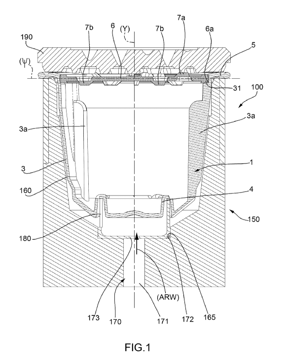
In figures 1, 6, 7, numeral 100 indicates as a
whole a preferred embodiment (according to the present
invention) of a system for the preparation of a beverage
CA 02813055 2013-03-21
WO 2012/042487 5
PCT/1B2011/054274
starting from an infusion product contained in an
interchangeable capsule 1.
The system 100 comprises an interchangeable capsule
1, which will be described hereinafter in greater
detail, and a percolating machine 150 for the
preparation of infusions.
The percolating machine 150 comprises, in turn, a
receptacle 160 (figure 1) adapted to contain the
interchangeable capsule 1 and a dispensing device 170
for a pressurized fluid, in particular, pressurized
water.
With reference in particular to figures 2, 3, 4, 5,
8, the interchangeable capsule 1 will be now described
in greater detail before returning to the detailed
description of the operation of the system 100.
Both incidentally and in the present context, the
words "interchangeable capsule" must be understood as a
capsule, usually for single use, of the disposable type,
meaning that after infusing the granular product
contained in the capsule such a capsule is disposed of
(with all the product to be infused already used inside)
removing it from the receptacle of the percolating
machine. Evidently, a first "interchangeable capsule",
once used and disposed of, is replaced, in general, by a
second capsule of the same type, which takes the place
of the first capsule in the specific receptacle of the
percolating machine.
CA 02813055 2013-03-21
WO 2012/042487 6
PCT/1B2011/054274
The capsule 1 (figure 5) comprises a cup-shaped
structure 2 made in a single truncated-cone-shaped body
and defined by a side wall 3, by a bottom wall 4, and by
a flat circular crown 5 which extends radially from an
upper edge of the side wall 3. As we will see, such a
flat circular crown 5 supports the cup-shaped structure
2 in the specific receptacle 160 of the percolating
machine 150 (figure 1) (see below).
Furthermore, three longitudinal ribs 3a arranged
equally spaced apart by 120 extend towards the inside
of the side wall 3. As explained in greater detail
below, the three ribs 3a are used to reinforce the side
wall 3 and are additionally used to break the streams of
hot pressurized liquid in the cup-shaped structure 2
itself so as to take the hot water during the step of
percolation into more intimate contact with the granular
product to be infused. What is more, the three ribs 3a
are also used to avoid the spontaneous stacking of the
capsules 1 during the automatic handling for filling
with the infusion product. In other words, the three
ribs 3a on the inner wall of the cup-shaped structure 2
prevent the capsules 1 from being randomly and
involuntarily stacked inside each other. If this were
not so, i.e. if a cup-shaped structure 2 could randomly
enter inside another cup-shaped structure 2, an
incorrect handling and filling of all the cup-shaped
structures 2 with the product to be infused would occur.
CA 02813055 2013-03-21
WO 2012/042487 7
PCT/1B2011/054274
The cup-shaped structure 2 is made of a rigid
plastic material or a thermosetting plastic material;
preferably the plastic material used being of the
biodegradable type.
The capsule 1 further comprises a lid 6 which
closes the free mouth of the cup-shaped structure 2
(figures 3, 4, 5) allowing the entrapment of the
granular material (not shown) to be infused inside the
cup-shaped structure 2 itself. As shown in particular in
figure 5, the lid 6 is arranged inside the circular
crown 5 so that the upper edge of the side wall 3 is
underneath the lid 6 itself.
The lid 6 has a substantially circular shape in the
particular embodiment shown in figures 3, 4. In use, the
lid 6 is accommodated in a circular, crown-shaped recess
6a obtained in the upper area of the wall 3. The lid 6
is also made of a rigid plastic material.
As shown in greater detail in figure 8, the upper
part of the recess 6a includes an edge 66, which has an
annular shape and projects internally towards a
longitudinal symmetry axis (Y) of the cup-shaped
structure 2. Such an edge 66 is also made of a plastic
material and can thus be elastically deformable so as to
allow the insertion of the lid 6 in the recess 6a.
During the step of automatic coupling of the lid 6 with
the respective cup-shaped structure 2, such a lid 6 is
thus tightened between the bottom of the recess 6a, on
CA 02813055 2013-03-21
WO 2012/042487 8
PCT/1B2011/054274
one side, and the edge 66, on the other. Indeed, during
the packaging of the capsule 1 in a specific packing
machine (of known type and not illustrated), such a
capsule 1 is subjected to high accelerations and thus,
if the lid 6 were not tightened between the aforesaid
elements, there would be the actual risk of a detachment
of the lid 6 from the respective cup-shaped structure 2,
with a consequent undesired spillage of product in the
packaging machine.
What is more, as shown in particular in figure 8,
there is a circular relief 31 on the bottom of the
recess 6a. With the known methods, after filling the
cup-shaped body 2 with the product to be infused and
closing such a cup-shaped body 2 with the lid 6 in the
aforesaid manner, the method proceeds with the localized
melting (e.g. by means of ultrasounds) of the circular
relief 31 only, so as to obtain a definitive fastening
of the lid 6 to the bottom of the recess 6a.
The inner face of the lid 6 may be provided with a
filter (not shown) of any type suited to the need. In
particular, such a filter is, as known, elastically
deformable.
The circular relief 31 may be either of the
continuous type or of the interrupted type, meaning
that, in the latter case, such a circular relief 31
consists of circular segments, e.g. three in number
offset by 120 with respect to each other. The latter
CA 02813055 2013-03-21
WO 2012/042487 9
PCT/1B2011/054274
solution is shown in figure 2 where each circular relief
31 is placed at a rib 3a.
As still shown in figure 8, a sealing annular rib
32 having triangular section with a rayed tip is
provided on the lower surface of the circular crown 5.
It has been found that the best results concerning
the sealing of the capsule 1 with respect to the
receptacle 180 of the system 100 are obtained if a
sealing thickening 33 of the circular crown 5 is made
(figure 8) at the sealing annular rib 32. As can be
observed in figure 8 such a sealing thickening 33 is
distributed on both faces of the circular crown 5.
In the embodiments shown in the accompanying
figures (see in particular figures 3, 4), the lid 6 has
a plurality of valves 7, arranged to allow the release
of the infused beverage made by mixing hot water with
the infusion product.
More in particular, the valves 7 may be of a first
type, indicated by 7a, or of a second type, indicated by
7b. Both types 7a, 7b open towards the external (figure
4).
As shown, for example in figure 1, the valves 7a
are on the opposite side of the valves 7b with respect
to a symmetry plane (*) of the lid 6. In this manner, at
least a portion of the valves 7a, 7b will certainly open
by effect of the action exerted by the infusion water.
The choice of having two types of valves 7a, 7b was
CA 02813055 2013-03-21
WO 2012/042487 10
PCT/1B2011/054274
dictated by the need to simplify, as much as possible,
the packaging machine (not shown) of the capsules 1.
Indeed, if all the valves 7 were of type 7a, the
packaging machine would need to orient the lids 6 during
the coupling with the cup-shaped body 2. This would
imply an evident complication (above all on sensor
level) of the packaging machine of the capsules 1
complete with product. Instead, by adopting two types of
valves 7a, 7b in the same lid 6, how the lid 6 is
mounted in the recess 6a is indifferent.
An enlargement of a generic valve 7a is shown in
figure 7.
The valve 7a (but the same conditions obviously
apply also to the valve 7b) has a respective cavity 8
and a respective flap 9 hinged to the rest of the lid 6
by means of a hinge 10, on one side, and a through cut
11 on the other.
In one embodiment (not shown), there is a
preferential breakage line, which is broken by the
pressurized liquid, instead of the through cut 11.
In actual fact, in the embodiment suggested in the
accompanying figures the flap 9 is simply the bottom of
the cavity 8.
In use, the pressure of the infused product
attempting to exit from the cup-shaped body 2 exerts a
force on the flap 9 making it turn about the hinge 10
according to an arrow (F1) (figure 7), towards the
CA 02813055 2013-03-21
WO 2012/042487 11
PCT/1B2011/054274
outside of the cup-shaped structure 2.
In particular, each flap 9 has a rectangular plan
and a trapezoidal longitudinal section, and in case of a
valve 7a, extends completely within the cup-shaped body
2 thus forming the respective cavity 8.
Advantageously, but not necessarily the valves 7
are obtained in one piece with the respect to the lid 6
by means of a single molding operation of a plastic
material.
As clearly illustrated in figure 5, the bottom 4
comprises an annular hollow 12 arranged in symmetric
position with respect to the longitudinal symmetry axis
(Y) of the cup-shaped structure 2. A respective annular
groove 13 which faces the outside of the cup-shaped
structure 2 corresponds to the annular hollow 12.
Furthermore, the bottom 4 has an indentation 14 at
axis (Y).
The presence of the annular hollow 12 and of the
indentation 14 is motivated by the need to confer
appropriate stiffening to the bottom 4, in particular
due to the high pressure of the water to which the
bottom 4 itself must be subjected.
As shown again in figure 5, there are four valves
17 (only one of which is visible in figure 5), offset by
90 with respect to each other on the bottom of the
annular groove 13.
Each valve 17 has a respective flap 18 hinged to
CA 02813055 2013-03-21
WO 2012/042487 12
PCT/1B2011/054274
rest of the bottom 4 by means of a hinge, on one side,
by a hinge 19, while a through cut 20 is provided on the
other side.
In an embodiment (not shown) there is a
preferential breakage line which is broken by the
pressurized liquid, instead of the through cut 20.
The hot water distributed by the dispensing device
170 exerts a force on the flap 18 making it turn about
the hinge 19 according to an arrow (F2) (enlargement in
figure 5) towards the inside of the cup-shaped structure
2.
In particular, each flap 18 has a rectangular plan
and substantially rectangular longitudinal section and,
if stressed by the pressurized water extends within the
cup-shaped structure 2.
Advantageously, but not necessarily, the four
valves 17 are obtained in one piece with the rest of the
bottom wall 4, and thus with the rest of the cup-shaped
structure 2, by means of a single molding operation of a
rigid plastic material.
We will now go back to the system 100 shown in
figures 1, 6, 7.
A substantially cylindrical recess 165 is provided
in the central part of the receptacle 160 and adapted to
contain part of the aforesaid dispensing device 170.
Such a dispensing device 170, in turn, comprises a
feeding duct 171 of the hot liquid and a distribution
CA 02813055 2013-03-21
WO 2012/042487 3
PCT/1B2011/054274
1
chamber 172 accommodated, at least partially, in the
recess 165.
The distribution chamber 172 is in fluid
communication on one side with a feeding pipe 171 by
means of an opening 173, and, on the other side, with
the annular groove 13. In brief, the pressurized hot
water flows from the feeding pipe 171 to the annular
groove 13 passing through the opening 173 according to
an arrow (ARW).
The dispensing device 170 further comprises three
perforation needles 180 (only one of which is visible in
figure 5) arranged at 120 from each other. In other
words, the perforation needles 180 constitute the
traditional means provided in a plurality of percolating
machines for perforating the bottom of the capsule 1. In
use, the perforating needles 180 move towards the bottom
4 of the cup-shaped structure 2.
If there are preferential breakage lines instead of
the through cuts 20, the pressure of the liquid is such
to break such preferential breakage lines and, as
mentioned, the flaps 18 turn about the hinges 19
(according to arrow (F2)), thus allowing the passage of
pressurized hot water from the annular groove 13 to
inside the cup-shaped structure 2. It is worth noting
that the four valves 17 are all on the bottom of the
annular groove 13, in use, the needles 180 are located
inside such an annular groove 13.
CA 02813055 2013-03-21
WO 2012/042487 14
PCT/1B2011/054274
In actual fact, in the case in hand, the
perforating needles 180 do not perforate the bottom 4 in
any manner, but the flaps 18 are only deformed by effect
of the pressurized fluid distributed by the dispensing
device 170.
It is also worth noting that, as mentioned, there
are four valves 17, while there are three perforating
needles 180. Thus, it is always certain that at least
two perforating needles 180 always touch, without
pushing, at least two flaps 18.
Thus, the fact that the perforating needles 180
touch the flaps 18 without pushing them allows, on one
hand, to retrieve useful space to have more granular
material to be infused in the cup-shaped structure 2,
and, on the other hand, prevent that the flaps 18 can be
sheared by the perforating needles 180 themselves and
enter the infusion liquid. If this occurred, i.e. if
there were particles of plastic or metal suspended in
the infusion liquid, nearly certainly such particles
would be ingested by the consumer with evident negative
consequences.
Reference is made to figure 7 instead with regards
to the valves 7a, 7b on the lid 6.
In the system 100, the receptacle 160 is closed at
the top by an upper closing element 190 of the
receptacle 160.
As shown in figure 7, a collection chamber 191 of
CA 02813055 2013-03-21
WO 2012/042487 15
PCT/1B2011/054274
the fluid after percolation is thus defined between the
lid 6 and the upper closing element 190. In other words,
all the percolated fluid which has already completely
crossed the cup-shaped structure 2 and has exited from
the valves 7 is accumulated in the collection chamber
191. It is worth noting that, there being no mechanical
opening elements of the valves 7, it is the pressure of
the water itself inside the cup-shaped structure 2 that
opens the valves 7 themselves. From a closing position
under the bias of the pressure of the percolated fluid,
the valves 7 shift from a closing position of the outlet
area to an opening position of the outlet area thus
remaining in such an opening position also when the flow
of percolated fluid is interrupted. The configuration of
the lid 6 is thus permanently modified. It is worth
noting that because the valves 7 remain in the opening
position also after the interruption of the percolated
fluid flow nothing else flows out from the cup-shaped
structure 3 because the aforesaid filter (not shown)
applied to the lid 6 blocks any passage of parts of the
infusion product towards the outside. Being made of
elastically deformable material, such filter is deformed
but not perforated during the opening of the valves 7.
Furthermore, as shown again in figure 7, by
graduating the height (H) of the collection chamber 191
it is possible to consequently graduate also the opening
of the flaps 19 of the valves 7, and thus the water
CA 02813055 2013-03-21
WO 2012/042487 16
PCT/1B2011/054274
pressure in the capsule 1 being equal, to graduate the
outlet speed of the water itself from the valves 7. By
varying the height (H) the contact time of the water
with the granular product to be infused can be
indirectly graduated. Such a permanence time must be
balanced and thus sufficiently long to allow, at the
same time, a good infusion of the granular product
without being excessively detrimental to the rapidity of
the percolation operation.
In use, once a capsule 1 is inserted in the
receptacle 160, such a receptacle 160, with respective
dispensing device 170, is moved against the upper
closing element 190 as shown in figure 1. The
pressurized hot water will start flowing from the pipe
171 towards the annular groove 13 and the valves 17
which will open by effect of the pressure of the water
itself. Once the pressurized hot water enters in the
cup-shaped structure 2 it will start flowing towards the
lid 6 without having preferential flow lines. Under the
bias of the pressure of the percolated fluid the valves
17 shift from a closing position of the inlet area to an
opening position of the inlet area thus remaining in
such an opening position also when the flow of
percolated fluid is interrupted.
Furthermore, preferably, but not necessarily
introduction gaps of the water in the valves 17 oriented
so as to create substantially tubular paths of the
CA 02813055 2013-03-21
WO 2012/042487 17
PCT/1B2011/054274
percolation fluid in the interchangeable capsule 1 can
be included in order to encourage the turbulence of the
water inside the cup-shaped structure 2, in order to
involve as much granular material as possible in the
percolation operation. The valves 17 create jets of
pressurized hot water preferably directed against the
side wall 3. Such jets are introduced by the ribs 3a
creating the desired turbulence in the cup-shaped
structure 2.
The main advantages of the system described above
are:
- considerable increase of the amount of granular
product in the cup-shaped body;
- possibility of graduating the permanence time of
the hot water in contact with the granular product; and
- practically complete elimination of the
preferential flow lines of the hot water in the cup-
shaped structure; and
- complete elimination of any risk of contamination
of the beverage there being no broken fragments coming
from the bottom and/or the lid.