Note: Descriptions are shown in the official language in which they were submitted.
CA 02813407 2013-04-02
WO 2012/048272
PCT/US2011/055448
DETECTION AND SELECTION OF A REFERENCE SIGNAL FOR NETWORK-BASED
WIRELESS LOCATION
CROSS-REFERENCE TO RELATED APPLICATIONS
[0001] This application claims the benefit of U.S. Patent Application No.
12/900,858, filed October 8, 2010, the disclosure of which is incorporated
herein by
reference in its entirety.
TECHNICAL FIELD
[0002] The present invention relates generally to methods and apparatus for
locating
wireless devices, also called mobile stations (MS), such as those used in
analog or digital
cellular systems, personal communications systems (PCS), enhanced specialized
mobile
radios (ESMRs), and other types of wireless communications systems. More
particularly, but
not exclusively, the present invention relates to the system and method for
detecting and
selecting the correct reference signal in the presence of interfering co-
channel signals for
correlation processing in a wireless location system (WLS).
BACKGROUND
[0003] First commercially deployed in 1998 by TruePosition in Houston, Texas,
overlay network-based wireless location systems have been widely deployed in
support of
location-based services including emergency services location. Network-based
systems rely
on the reception of the wireless device originated uplink mobile transmission,
which is used
in a time-of-arrival (TOA), time-difference-of-arrival (TDOA), power-of-
arrival (POA),
power-difference-of-arrival (PDOA) or angle-of-arrival (AoA) location
calculation. Network-
based location calculations can be combined with mobile-based measurements,
collateral
information, or with other network-based location calculations to form hybrid
locations.
[0004] As realized and noted in extensive prior art, the ability to routinely,
reliably,
and rapidly locate cellular wireless communications devices has the potential
to provide
significant public benefit in public safety and convenience and in commercial
productivity.
[0005] A cellular network is designed to exploit frequency reuse. That is,
careful
planning and surveying of radio transmission frequencies to control adjacent
and co-channel
interference is performed in a cellular network on a more-or-less continuous
basis. In
- 1 -
CA 02813407 2013-04-02
WO 2012/048272
PCT/US2011/055448
addition to frequency planning, the various wireless communications protocols
were also
designed to both minimize and tolerate adjacent and co-channel interference.
Techniques for
minimizing such interference include SAT tones in AMPS, color-codes in IS-136,
frequency
hopping patterns in GSM, code separation in CDMA (IS-95 & IS-2000) and UMTS
(also
known as W-CDMA), and both frequency hopping patterns and zero-autocorrelation
Zadoff-
Chu sequences in LIE,.
[0006] Since a network-based WLS relies on receiving the signal from the
mobile-
of-interest at geographically distributed land-based receivers, the likelihood
of co-channel
interference is increased since the geographic reuse pattern of the underlying
cellular network
cannot be relied on to isolate transmissions.
[0007] As detailed in the United States Patent 5,327,144, "Cellular telephone
location system," and United States Patent 6,047,192, "Robust, efficient,
localization
system", correlation processing of signals received by geographically
separated wireless
receivers can be used with extremely weak signals such as those found in
frequency reuse
cellular systems to generate time-difference-of-arrival (TDOA), angle-of-
arrival (AoA), and
hybrid TDOA/AoA location and velocity estimates.
[0008] The inventive techniques and concepts described herein apply to time
and
frequency division multiplexed (TDMA/FDMA) radio communications systems
including
the widely used IS-136 (11)MA), GSM, and OFDM wireless systems, as well as the
OFDM-
based WYMAN (MEE-802.16), WiMAX (MEE-802.20), and Long Term Evolution (LTE,)
Evolved Universal Terrestrial Radio Access Network (EuTRAN). The Global System
for
Mobile Communications (GSM) model discussed above is an exemplary but not
exclusive
environment in which the present invention may be used.
[0009] The following U.S. patents describe systems and methods of interference
cancellation and antennae selection in association with a wireless location
system: U.S.
Patent No. 6,765,531 B2, July 20, 2004, "System and Method for Interference
Cancellation
in a Location Calculation, for Use in a Wireless Location System"; and U.S.
Patent No.
6,661,379, December 9, 2003, "Antenna Selection Method and System for a
Wireless
Location System". These provide further background information relating to the
presently
described subject matter.
- 2 -
CA 02813407 2013-04-02
WO 2012/048272
PCT/US2011/055448
SUMMARY
[0010] In a wireless communications system, a network-based wireless location
system using geographically distributed land-based receivers may suffer
interference on the
signal received from the mobile-of-interest. Using a correlation matching
between the
received signal and the expected signal allows the wireless location system to
determine a
detected frame sequence at each receiver. In some modes, such as Discontinuous
Transmission Mode (DTX) in a GSM network, the mobile does not transmit in all
of its
assigned frames. The same is true in the LTE environment in which case the
frequency / time
assignment combinations may go unused while the mobile is in DTX. Though the
exact
frames that the mobile selects to transmit when in DTX mode are not known by
the network,
the mobile transmissions tend to occur in "bursts" and the pattern of the
frames detected can
be analyzed to determine the likelihood that the mobile-of-interest has been
identified. By
ignoring large frame offsets for otherwise valid detections and biasing the
detection metric
toward favoring small, repeated frame offsets indicative of bursty
transmissions, selection of
the mobile-of-interest over the interfering mobile is enhanced and thus the
correct reference
signal for location estimation can be determined.
BRIEF DESCRIPTION OF THE DRAWINGS
[0011] The foregoing summary as well as the following detailed description are
better understood when read in conjunction with the appended drawings. For the
purpose of
illustrating the invention, there is shown in the drawings exemplary
constructions of the
invention; however, the invention is not limited to the specific methods and
instrumentalities
disclosed. In the drawings:
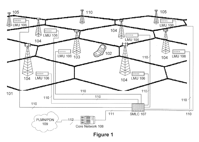
[0012] Figure 1 schematically depicts a wireless location system deployed
within a
wireless communications network.
[0013] Figure 2a illustrates frequency hopping transmissions of a mobile to be
located.
[0014] Figure 2b illustrates frequency hopping transmissions of an interfering
mobile.
[0015] Figure 3a depicts a correlation signal representing the correlation of
a signal
from the mobile-of-interest with an expected signal.
[0016] Figure 3b depicts a correlation signal representing the correlation of
a signal
from an interfering mobile with the expected signal.
- 3 -
CA 02813407 2013-04-02
WO 2012/048272
PCT/US2011/055448
[0017] Figure 4a graphically depicts a 7-cell frequency reuse pattern in a
wireless
communications system.
[0018] Figure 4b graphically depicts a 4-cell frequency reuse pattern in a
wireless
communications system.
[001.9] Figure 4c graphically depicts a 3-cell frequency reuse pattern in a
wireless
communications system.
[0020] Figure 4d graphically depicts a 1-cell frequency reuse pattern in a
wireless
communications system.
[0021] Figure 5 diagrammatically depicts the two stage signal reception and
selection for wireless location.
DETAILED DESCRIPTION OF ILLUS IRATIVE EMBODIMENTS
[0022] We will now describe illustrative embodiments of the present invention.
First, we provide a detailed overview of the problem and then a more detailed
description of
our solutions.
[0023] As wireless usage increases and the need for spectral efficiency grow,
wireless network operators will adjust frequency reuse patterns and power
settings to
maximize potential traffic. Examples of frequency reuse patterns can be seen
in Figures 4a,
4b, 4c, and 4d. One form of power control is discontinuous transmission (DTX)
in which the
mobile greatly reduces transmission during periods of inactivity. DTX has the
dual benefit of
reducing interference in neighboring cells while also lowering mobile device
power
consumption and is thus a highly favored power-control option.
[0024] For a network-based wireless location system that uses geographically
distributed receivers to collect and timestamp the uplink (mobile-to-base
station) radio
signals, both tighter frequency reuse and implementation of DTX increase the
probability of
an interfering mobile being mistaken for the mobile-of-interest. As an example
scenario, the
mobile-of-interest (the mobile to be located) is active and in DTX, being
served by a base
station in the cellular wireless network. In the DTX mode, the mobile
transmits in a "bursty"
mode (usually four consecutive frames in the case of GSM) with long periods of
no
transmission in between. An interfering mobile is served by a nearby base
station in a
neighboring or proximate cell. The interfering mobile may be in DTX also, but
for this
example is not, which raises the probability of interference. The timing of
the two base
stations is fairly close (this can occur randomly in an unsynchronized
TDMA/FDMA system
- 4 -
CA 02813407 2013-04-02
WO 2012/048272
PCT/US2011/055448
such as the GSM system or the OFDM-based LTE system). The two mobiles are
assigned to
the same training sequence and to different frequency hopping patterns, but
some frequencies
are used by both mobiles and the hopping patterns collide randomly, resulting
in both
mobiles being assigned to the same frequency at the same time. The timing is
close enough
for preamble /midamble (or even post-amble) detection and thus uplink frames
from the
interfering mobile can be mistaken for frames from the mobile-of-interest.
[0025] The WLS is tasked to locate the mobile-of-interest. Network and radio
channel information is made available to the WLS by the wireless
communications network
(WCN). In GSM, this information includes serving cell, radio frequency,
training sequence
(midamble in this example, but this could be a pre-amble or post-amble),
frequency hopping
pattern, and timeslot. Using this information, the WLS tasks the LMUs assigned
to the pre-
established primary sectors and secondary sectors for the serving cell in an
effort to collect
the best quality signal to serve as the reference signal for later correlation
processing. This
signal processing method and resulting gain allows for large numbers of
antenna elements to
participate in a given location attempt. The large number of antenna elements
improve
statistical success of the location process providing immunity to local
interference at a given
cooperating cell site, a lower variance in accuracy, excellent yield (greater
than 99% for a
single location attempt) and the ability to achieve reliable indoor
performance despite the
attenuation of building structures.
[0026] Since, in the GSM system, the midamble (comprised of the transmitted
training sequence) is present in every frame and is known to the WLS,
correlation of the
WCN-provided training sequence with the received midamble allows for quick
detection and
classification by quality metric of the reference signal from the mobile-of-
interest. Since
there are only eight defined GSM training sequences, re-use of the same
midamble within a
small area is common.
[0027] However, if an interfering mobile, using the same midamble and randomly
hopping onto the same frequency assigned to the mobile-of-interest in that
timeslot, is
detected well enough at one or more secondary LMU sectors to provide the
highest detection
metric, the wrong signal may be selected as the reference signal. Once the
interfering mobile
is chosen as the reference, its waveform will then be distributed to the co-
operating receivers
and located by the WLS. Since the interfering mobile provided a strong
reference signal, the
location result for the interfering mobile (and not the mobile-of-interest) is
often precise with
- 5 -
CA 02813407 2013-04-02
WO 2012/048272
PCT/US2011/055448
high confidence. In reality, since the wrong mobile was located, the
inaccuracy can be in the
several kilometers range despite the high confidence. When discovered in drive
testing, these
precise and yet inaccurate locations were deemed "wild locates". We repeat
this terminology
below.
[0028] To minimize the occurrence of wild locates, a method for weighting the
detection metric to favor the target mobile-of-interest even in the presence
of the interfering
mobile has been created. The detection metric approach was favored as it has
no impact and
requires no changes on the underlying WCN. Changes to the core WLS algorithms,
such as
constraining the number of secondary sectors, was also rejected since such a
change could
lower overall WLS accuracy and would require tailoring to meet the varying
cell site density
and cell site deployment density (number of BTS with co-located LMU) for each
market. An
important component of the weighting algorithm is based on the numerical
distribution of the
frame offset list. Frame offset sequences with sequences of small offsets
(e.g., representing
groups of consecutive frames) interspersed with larger offsets representing
DTX silent
periods are favored over sequences of more evenly distributed offsets
(representing random
collisions in the two hopping sequences), even if the interfering sequence has
a higher
detection metric and/or more frames detected.
[0029] No consistent relationship between the signal strength at the detecting
LMU
and at the interfering LMU was found. Weighting of one receiver's detection
metric over
another receiver's by the number of detected bursts was found to be a
generally good
indicator but, due to DTX for the MOT, could still lead to selection of the
interfering mobile
over the MOT.
[0030] Testing showed a superior selection of the MOI when the detection
metric
weighting is determined by evaluating the number of frames between subsequent
detected
bursts ("frame offsets"). In a GSM system, a mobile device in DTX mode
generally transmits
in groups of four consecutive frames, while an interfering phone's hopping
pattern will
collide randomly.
[0031] Since it was desired to focus on groups of consecutive, or near
consecutive,
frames while disregarding expected long periods of silence, a weighting factor
was developed
by discarding a portion (e.g., the numerically larger half) of the frame
offsets and averaging
the remaining offset values. The detection metric from each LMU was then
divided by its
weighting factor to produce the set of weighted metrics used in selection of
the reference.
- 6 -
CA 02813407 2013-04-02
WO 2012/048272
PCT/US2011/055448
[0032] The detection algorithm was further adjusted to consider the detected
number of frames and to correctly handle cases with a very small number of
detected frames.
[0033] The revised algorithm identified the vast majority of apparent cases of
selection of the wrong mobile, with very few instances of selection of the
wrong reference in
other cases.
[0034] In testing, using field-collected data in simulation with the revise
algorithm,
location improvement varied widely from market to market, and is very heavily
skewed
toward calls with the largest errors. In the instances addressed by this
method, the interfering
mobile is far enough away to be served by a cell using the same training
sequence and at least
some of the same channels in its hopping sequences ¨ usually at least on the
order of twice
the cell site spacing in the area.
Reference Detection Metric and Weighted Metric
[0035] In the selection of the reference signal, the primary LMU and the set
of
secondary LMUs are requested by the SMLC to demodulate the signal of interest,
in this
case, the midamble or CZ sequence in the uplink signal on the established
channel. Each
LMU (the primary and all secondaries) then return a response that includes:
= Strongest Receive Antenna (sector)
= Signal Strength at Strongest Receive Antenna
= Frequency offset from channel
= Frames counted
= Reference Detection Metric (RDM)
[0036] The RDM is calculated by the LMU internally from the calculated signal-
to-
noise-ratio (SNR) of the midamble based on the number of corrupted bits in the
collected
training sequences and the number of frames detected.
[0037] In one exemplary embodiment, each primary or secondary LMU returns a
single RDM for the strongest (best signal/noise ) receive sector. In an
alternative
embodiment, to improve reference selection performance using the described
weighting
technique, each LMU may return RDM information separately for each receive
sector or the
weighting algorithm could be applied within the LMU to each sector
individually before
selection of that LMU's "best" sector.
[0038] The SMLC then weights the RDM received from each primary and
secondary LMU. An example weighting formula is:
- 7 -
CA 02813407 2013-04-02
WO 2012/048272
PCT/US2011/055448
RDMweighted = RDM * Wsector * Wsequence * sqrt (NumFrames)
where,
= NumFrames = the number of frames detected by this LMU during the
reference
selection stage;
= MaxFrames = the number of frames requested (typically 48 for traffic
channel
locations);
= RDM = Detection metric received from this LMU during the reference
selection
stage;
= Wsector
2 - if the metric is derived from the serving sector;
1.5 - if the metric is derived from a different sector at the serving site;
1 ¨ otherwise;
= Wsequence =
= (NumFrames / 10) - if NumFrames 5;
= (1 / the Mean of the Frame Offsets that are less than Median of
the Frame offsets) [essentially dropping the numerically larger
half of the Frame Offsets in the GSM_TDOA_DETECTION
message and averaging the remaining values] if 6
NumFrames < MaxFrames;
= Otherwise 1 if NumFrames = MaxFrames.
[0039] The SMLC will then select as the reference the LMU (or LMU sector) with
the highest weighted metric. The WCN designated serving sector is
automatically selected
for LMU signal collection if all the returned RDM are zero.
[0040] Figure 1 depicts a wireless communications network 101 with network-
based wireless location facilities 106 107. The wireless communications
network (WCN) 101
comprises distributed base transceiver stations (BTS) or access points 103 104
105 106 110
interconnected to a core network 108, which in turn is interconnected via
radio or wired
means 112 to the public land mobile network (PLMN) and public data network
(PDN) 109.
In this example WCN 101, all BTS 103 104 105 110 are unsectored,
omnidirectional cells for
the ease of compression.
- 8 -
CA 02813407 2013-04-02
WO 2012/048272
PCT/US2011/055448
[0041] The network-based wireless location system (WLS) includes
geographically
distributed network of receivers 106 also known as Location Measurement Units
(LMUs) or
Signal Collection Systems (SCS). The location receivers 106 are commonly
hosted within or
co-located with BTS's 103 104 105 106 to share electrical, environmental, and
antenna
resources. Some BTS 110 do not have a co-located location receiver. The
location receivers
106 are backhauled to the serving mobile location center (SMLC) 107 via wired
or wireless
data links 110.
[0042] When a mobile device 102 (also known as a mobile phone, a cell phone, a
mobile station (MS) or user equipment (UE)) is to be located, the Core Network
108 provides
the SMLC 107 with radio channel and network information for the mobile device
102 to be
located. This network information includes the serving cell 103 identity. The
SMLC 107 has
databased information on the WCN 101 allowing for the determination of
neighboring cells
104 and proximate cells 105 equipped with location receivers 106 that can be
used in the
signal collection phase of the wireless location.
[0043] Figure 2a depicts a time 201 frequency 202 map for the uplink (mobile
to
BTS) transmissions from the mobile-to-be-located (also known as the mobile-of-
interest or
MOI). As in the GSM and LIE wireless communications networks, the mobile
transmissions
are hopped in a known sequence. The example sequence depicted here has 8
hopped frames
over the sample period 204 and received frequency range 203.
[0044] As shown in the 4th hopped transmission frame 205, each frame contains
a
training sequence of known bit sequence or ZC sequence 206. The training
sequence is used
in GSM to synchronize uplink transmissions and is mandatory in all frames
transmitted from
the MS. In LTE the Zadoff-Chu sequence is used as pilot signal to perform
frequency domain
channel estimation and also must occur in every uplink frame. In Figure 2a,
the mobile
device has been placed in DTX mode and later frames in the hopping sequence
207 are not
transmitted.
[0045] Figure 2b depicts a time 201 frequency 202 map for the uplink (mobile
to
BTS) transmissions from an interfering mobile to the actual mobile-of-
interest. As in the
GSM and LIE wireless communications networks, the mobile transmissions are
hopped in a
known sequence. The example sequence depicted here has 8 hopped frames over
the sample
period 204 and received frequency range 203. Note that the frequencies in the
hopping
- 9 -
CA 02813407 2013-04-02
WO 2012/048272
PCT/US2011/055448
pattern match the MOI (Figure 2a) uplink transmissions in only frames f(q),
f(q+4), f(q+6),
and f(q+7).
[0046] As shown in the hopped transmission frames 208, the interfering mobile
transmits a frame 208 in the same frequency and during the same (approximate)
time as the
MOI. The interfering frames 208 also contain the training sequence of known
bit sequence
(in GSM) or a ZC sequence 208 (in LTE).
[0047] Figure 3a and 3b are used to show the collision between a mobile-of-
interest
and an interfering mobile as represented as cross-correlations between the
received signal and
the hopped training sequence. The training sequence can be directly correlated
with received
signal or demodulated from the received signal than correlated. Figure 3a
shows the cross-
correlation between the received signal from the mobile of interest (MOI) and
the training
sequence. This time 301, correlation 302 graph shows the same 8 frames as the
signal 303
shown in Figure 2a, but cross-correlated with the re-modulated training
sequence. Due to
DTX, only frames q, q+1, q+2, and q+3 are transmitted by the MOI. A detection
threshold
304 has been established to prevent false positives. The signal 303 exceeds
the detection
threshold in 4 of the 8 frames but at much higher power, representing a
stronger signal then
the interfering signal detailed in Figure 3b. The sequence of detected frames
is indicated in a
series of offsets representing the number of frames between successive
detections. In the case
of the MOI, the offsets corresponding to Figure 3a could be represented by 1,
1, 1. This is
indicative of a transmission comprised of bursts of sequential transmitted
frames.
[0048] Figure 3b shows the cross-correlation between the received signal from
the
interfering mobile and the training sequence. This time 301, correlation 302
graph shows the
same 8 frames as the signal 305 shown in Figure 2b, but cross-correlated with
the re-
modulated training sequence. In this case, the interfering mobile is not in
DTX and is
transmitting each frame in its assigned sequence, but since the receiver is
following the
hopping sequence of the MOI (Figure 2a), only frames that are transmitted on
the assigned
frequency of the MOI in each frame are detected. A detection threshold 304 has
been
established to prevent false positives. The correlation with the interfering
signal 305 exceeds
the detection threshold 304 in 3 of the 8 frames. The interfering signal may
be at a higher
power level (for those LMUs in proximity) than the MOI, which contributes to
the interferer
generating a higher unweighted metric, confusing selection of the correct
reference. In the
case of the interfering mobile, the offsets corresponding to Figure 3b could
be represented by
- 10-
CA 02813407 2013-04-02
WO 2012/048272
PCT/US2011/055448
4, 2, 1. This is indicative of the random collision of the hopping sequences
of the two
mobiles.
[0049] Cellular frequency reuse patterns were originally conceived to minimize
co-
channel interference between users. Large cellular reuse patterns (e.g. 11
cells, 7 cells) also
have the advantage that no coordination of frequency use between base stations
was required.
As cellular reuse patterns tighten in an effort to increase total system
throughput, there is an
increased chance of an interfering mobile device when a network-based wireless
location is
being performed. In Figures 4a, 4b, 4c, and 4d, frequencies are represented by
letters.
[0050] Figure 4a shows the classic 7-cell reuse pattern where adjacent and
proximate cells use different frequencies. In effect, an interfering mobile
transmission would
come from over 2 BTS diameters away.
[0051] Figure 4b shows the 4-cell reuse pattern. In this pattern, interfering
mobile
transmissions would arrive attenuated by at least a full BTS diameter.
[0052] Figure 4c shows the 3-cell reuse pattern. In this pattern, interfering
mobile
transmissions would arrive attenuated by at least a BTS diameter.
[0053] Figure 4a shows the 1-cell reuse pattern. In this pattern, interfering
mobile
transmissions are expected and may require inter-BTS coordination to minimize
interference
and advanced signal processing to mitigate interference.
[0054] Figure 5 shows the entire location process for a network-based wireless
location system using uplink time-difference-of-arrival (U-TDOA) for location
calculation.
First the mobile device is active 501, in radio communication with the
wireless network The
uplink transmission may be on a control or traffic/data channel. The BSCAVISC
provides a
position request with channel assignment and network information to the SMLC
502, tasking
the WLS. The SMLC commands the LMUs at surrounding sites, based on the serving
cell, to
digitize and store RF energy 503. LMUs receive the signal of interest 504 at
multiple antenna
ports per base station, never less than one per sector, meaning that both
primary and
secondary sectors can be at the same LMU. Using the known midamble (or pre- or
post-
amble), cross-correlation with the received signal is used to produce a
received quality metric
505. This quality metric is delivered to the SMLC by all commanded LMUs 506.
[0055] The LMU with the best detection metric (usually the serving cell site's
serving sector) is selected by the SMLC as the reference while LMUs with
lesser detection
metrics above a threshold are selected as co-operating receivers 507.
- 11 -
CA 02813407 2013-04-02
WO 2012/048272
PCT/US2011/055448
[0056] The LMU at the reference site then distributes its received waveform
data
and sends it to the SMLC 508. The demodulated data is distributed to all
surrounding LMUs
509. The LMUs cross-correlate the reference waveform with their stored signal
data to
compute TDOA measurements 510. The LMUs then return the measurements to the
SMLC
511.
[0057] The SMLC computes the position, velocity, and error estimates 512. The
SMLC then reports the location data to the requesting or designated network
entity 513.
Conclusion
[0058] The true scope the present invention is not limited to the illustrative
or
presently preferred embodiments described herein. For example, the
illustrative details
described above in respect to the wireless location system (WLS) deployed
within a wireless
communications network (WCN), depicted in Figure 1, may be altered without
departing
from the scope of protection defined by the claims set forth below. In many
cases, the place
of implementation (i.e., the functional element) described herein is merely a
designer's
preference and not a hard requirement. The inventive techniques and concepts
described
herein apply to various time and frequency division multiplexed (IDMAJFDMA)
radio
communications systems. These include the widely used IS-136 (TDMA), GSM, and
ONDM
(WiMAX, LTE, LTE-Advanced) wireless systems, as well as code-division radio
communications systems such as CDMA (IS-95, IS-2000) and Universal Mobile
Telecommunications System (UTMS), the latter of which is also known as W-CDMA.
The
Global System for Mobile Communications (GSM) model is an exemplary but not
exclusive
environment in which the present invention may be used.
- 12-