Note: Descriptions are shown in the official language in which they were submitted.
CA 02814063 2013-04-08
WO 2012/050502 PCT/SE2011/000181
1
Railway track heating device
TECHNICAL FIELD
The present invention relates to devices for removing snow and ice from
railway
tracks and in particular from rail road switches.
BACKGROUND
In winter climates there is a high demand to keep railway tracks free from
snow and
ice. The methods and devices used for removing the snow and ice range from
manually removal to thawing and heating devices of different types.
For example US patent No 6664521 describes an inductive snow melting device.
The device in US 6664521 removes snow by heating a floor plate using a heating
coil that is fed with a high frequency current.
Today, there is a trend toward a higher use of railways for transportation of
goods
and people. This has led to a higher utilization of railways. This in turn has
resulted
in that the maximum capacity of railroads now has been reached or almost
reached
in many places. The railway must hence be constantly available and there is
little or
no time to manually remove ice or snow from the tracks or thaw them with
conventional thawing devices.
Hence there exists a need for new devices providing improved performance in
snow and ice removal from railway tracks.
SUMMARY
. .
,
=
2
It is an object of the present invention to provide an improved methods and
devices to
address the problems as outlined above.
According to an aspect of the present invention there is provided an
arrangement for
heating of railway tracks, the arrangement comprising a magnetic field
generator
configured to be fed with a low-frequency current, the magnetic field
generator being
formed without a circuit returning a magnetic flux generated by the magnetic
field
generator, and a heater in the form of a plate closing the magnetic flux
generated by
the magnetic field generator, wherein the plate is located between sleepers of
the
railway tracks.
In some embodiments, the heat is controlled by a heating sensor.
In some embodiments, the heating sensor is a thermostat.
In some embodiments, the low-frequency current is 16, 50 01 60 Hertz.
In some embodiments, the magnetic field generator comprises a core and at
least
one coil configured to generate a magnetic flux in the core when fed with the
low
frequency current.
In some embodiments, the core of the magnetic field generator is generally E
shaped.
In some embodiments, the plate is located under switch points of a railway
switch.
In some embodiments, the plate is made of aluminum.
In some embodiments, the plate is provided with holes and or slits.
CA 2814063 2019-01-29
2a
According to another aspect of the present invention there is provided a
method for
heating of railway tracks, the method comprising feeding a magnetic field
generator
with a low-frequency current, the magnetic field generator being formed
without a
circuit returning the magnetic flux generated by the magnetic field generator
and
closing the magnetic flux generated by the magnetic field generator via a
heater in
the form of a plate, wherein the plate is located between sleepers of the
railway
tracks.
As has been realized by the inventor, an inductive ice-melting and snow
removal
device making use of a high-frequency input current such as the device
described in
US patent No 6664521 has great limitations. For example, the need for high
frequency
components in an environment in need of ice-melting and snow removal is highly
unsuitable and can cause malfunction in the system. The mean-time before
failure
(MTBF) will also be short.
Further, high frequency components are not desired because there will be a
risk of
interference with other electrical devices, in particular radio frequency
devices.
The present invention solves the above problems in that an inductive heating
device
fed with a low-frequency current is provided. Thus, by generating heat with an
inductive heating device designed to operate on low-frequency current a number
of
advantages can be achieved.
In accordance with embodiments described herein a device for heating of
railway
tracks is provided. The device comprises a magnetic field generator fed with a
low-
frequency current. The magnetic field generator is formed by a device
generating a
magnetic flux without a circuit returning the magnetic flux generated by the
magnetic
field generator. Hereby the magnetic flux can be returned via a heater. The
heater is
CA 2814063 2019-01-29
. .
2b
a material generating heat when placed in the magnetic field from the magnetic
field
generator. The heater can be the railway tracks or a plate provided in
conjunction with
the railway tracks.
CA 2814063 2019-01-29
CA 02814063 2013-12-23
3
The use of an inductive heating device fed with a low-frequency current in
accordance with some embodiments will thus provide numerous advantages over
existing devices for removing snow and ice from railway tracks. The advantages
includes but are not limited to an effective use of the applied power, heat
generation
in a well-defined area, a simple and robust design with a high MTBF, and no
high
frequency radio frequency interference.
BRIEF DESCRIPTION OF THE DRAWINGS
The present invention will now be described in more detail by way of non-
limiting
examples and with reference to the accompanying drawing, in which:
- Fig. 1 is a-view of a railway track heating device,
- Fig. 2a - 5 are views depicting some parts of a railway track heating
device,
- Fig. 6 is a view of a railway switch, and
- Fig. 7 is a view of a heating device for removing snow and ice from a
railway
switch.
DETAILED DESCRIPTION
In Fig. 1 a general view of an exemplary heating device for heating railway
tracks is
depicted. The heating device is provided for the purpose of ice-melting and
snow
removal. This is also referred to as defrosting.
The railway track heating device in Fig. 1 is formed by a magnetic field
generator 1
formed by an induction core having a coil. The magnetic field generator is
operative
to work in conjunction with a heat element 3 in which the magnetic field
generated
by the magnetic field generator is transformed into heat. The heat element can
be a
section of the railway or some other metal portion having magnetic flux
properties
that are worse than the induction core. In particular the heat element can be
CA 02814063 2013-04-08
WO 2012/050502 PCT/SE2011/000181
4
combined with a heat spreader 2 as described below. Hereby, the magnetic flux
generated by the magnetic field generator will heat the heat element 3.
The heat element 3 can be supplemented by a heat spreader 2. The purpose of
the
heat spreader is to spread the heat generated in the heat element 3 over a
larger
area. The heat spreader can be secured to the railway tracks by means of a
securing device 4. The securing device can be clamped around the bottom
section
of the railway tracks and also be attached to the inductive core whereby the
heating
device can be held in place. The magnetic field generator is fed with a low
frequency power via a power cable 6. To control the heat generated by the
device a
thermostat 5 can be provided that is operative to turn the power supply off
and on in
response to the current temperature.
The magnetic field generator can be formed by an arrangement having a coil
driving a magnetic flux in an inductive core, but without a circuit returning
the
magnetic flux. Instead the heating device, such as the railway tracks or a
heat
element, will serve as a return for the magnetic field generated by the
magnetic field
generator. The railway tracks have poor properties for conducting a magnetic
flux.
As a result the railway tracks will generate heat when placed as a return
closing the
loop for the magnetic flux.
Some different parts of the device in Fig. 1 will now be described in more
detail with
reference to figures 2a ¨ 5.
In Fig. 2a a coil 11 that can be fed with a low frequency current is depicted
in a top
view. The coil can be formed by a material having good electrical conductive
properties such as copper. The low frequency current flowing through the coil
11
will cause the generation of a magnetic field. The frequency of the low-
frequency
current can be selected to any suitable value. However, the use of a current
CA 02814063 2013-04-08
WO 2012/050502 PCT/SE2011/000181
frequency already at hand where the magnetic field generator is to be deployed
is
typically advantageous. Hence, the coil can be fed with a current having a
frequency of 16, 50 or 60 Hz. In Fig. 2b the coil 11 is depicted from the
side. Also
more than one coil can be used for generating the magnetic flux.
In Fig. 2c a top view of an inductive core 10 is depicted. In Fig. 2d a side
view of the
inductive core 10 is shown. The inductive core in Figs. 2c and 2d is generally
E-
shaped and can be formed by a material having good properties for a magnetic
flux.
The inductive core can be made from transformer plates. In another embodiment
(not shown) the inductive core can be generally U-shaped. Other forms of the
inductive core are possible. In general the form of the core is such that a
magnetic
flux flowing in the core will need to be closed via some other material than
the core.
Hence the inductive core 10 will have a form without closed loops. Hereby a
coil
around the inductive core fed with an alternating current will drive a flux in
the
inductive core and where the flux will need to be closed outside the inductive
core.
This is generally referred to as a magnetic field generator herein.
In Fig. 2e, a top view of a magnetic field generator formed by a coil 11 and
an
inductive core 10 is shown. The coil is located around the mid-section of the
generally E-shaped inductive core. When fed with a low frequency current, a
magnetic flux will be generated inside the inductive core and on top of the
inductive
core. In Fig. 2f a top view of a magnetic flied generator formed by a coil 11
and an
inductive core 10 is shown.
In Fig. 3a a cross sectional view of a heater is shown. The heater comprises a
heat
spreader 2 with securing device 4. Also the bottom of the railway tracks is
shown.
Fig. 2b is a lateral view of the heat spreader and in Fig. 2c the heat
spreader is
shown in a top view. The heat spreader can be made from a plate of aluminum or
some other material with poor properties for conduct magnetic flux or stated
CA 02814063 2013-04-08
WO 2012/050502 PCT/SE2011/000181
6
differently having good properties for generating heat when placed in a
magnetic
flux. The heat spreader can be provided with holes or slits to increase the
heating
and to spread the heating better over the plate.
In Fig. 4a a cross sectional view of a heating device formed by the magnetic
field
generator of Fig. 2f when combined with the heater of Fig. 3a. Thus, the
heater,
generally denoted with reference numeral 13, is placed on top of the magnetic
field
generator formed by an inductive core 10 and having at least one coil 11 for
generating a magnetic flux. Because the arrangement formed by the inductive
core
and the at least one coil has no circuitry for returning the magnetic flux on
the top of
the magnetic field generator, the magnetic field on top of the magnetic field
generator will pass through the heater 13. The heater 13, which can be the
railway
tracks or a plate or some other suitable heat generating device, will return
the flux
to the inductive core and thereby close the loop for the magnetic flux
generated by
the at least one coil. The heater can be optimized to generate a maximum
amount
of heat from the magnetic flux flowing through the heater. To control the heat
a
thermostat 12 can be used. The thermostat 12 can be provided to control the
low
frequency current power fed to the coil 11. In Fig. 4b a lateral view of the
heating
device is shown. In Fig. 4c a top view of the heating device is shown.
In Fig. 5 another top view of the heating device is shown. In the top view of
Fig. 5
the purpose of the holes or slits in the heater 13, in particular the heat
spreader, is
illustrated. Thus by providing holes or slits in the heat spreader the
magnetic field
lines shown in Fig. 5 are made to go around the holes or slits thereby
spreading the
magnetic flux over a wider area, which turn spreads the heat better.
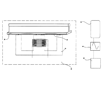
In Fig. 6, a railway switch 80 is depicted. The switch 80 is provided with
inductive
heaters 100. The inductive heaters can for example be any of the heating
devices
as described above. For example the heater can be a heater 13 as set out
above.
CA 02814063 2013-04-08
WO 2012/050502 PCT/SE2011/000181
7
The heater 100 is heated used inductive arrangements 110. The inductive
arrangements can be of the type described above formed by an inductive core 10
in
which a magnetic flux is generated by at least one coil, and where the
magnetic flux
is made to return via the heater 100. The heater can comprise a plate of the
type
described above which can be located between the sleepers 120 of the railway
track. In particular the heater can be located beneath the points of the
railway
switch. Hereby it is possible to keep the switch free from snow and ice.
In Fig. 7, a heating arrangement having a magnetic field generator in
accordance
with the above is shown. The magnetic field generator comprises a coil that
can
drive a magnetic flux in the E-shaped core. The arrangement can be said to
resemble a transformer arrangement without a circuit closing the magnetic
flux.
Hereby, a magnetic field 25 is generated outside the core. The arrangement is
used
to heat railway tracks 20. By providing a magnetic field generator in
conjunction
with railway tracks an arrangement whereby the railway tracks can be heated
using
a magnetic field generated by the magnetic field generator. The magnetic field
is
illustrated by magnetic field lines 25 in Fig. 7. The rails are hereby heated
using
induction. The magnetic field generator (the inductive core 10) will it self
not be
heated. Instead the magnetic field will generate heat in the metal forming the
railway tracks.
In accordance with some embodiments one or more magnetic field generators are
located between the sleepers of the railway track. Further, entire railway
sections
can be heated as one unit. Typically, the lateral heating is limited compared
to
vertical heating whereby the heating can be made local at locations where
heating
is deemed important and or desired. For example such locations can be railway
switches, which can become stuck due to ice and snow.
CA 02814063 2013-04-08
WO 2012/050502 PCT/SE2011/000181
8
As set out above, the magnetic field generator can be fed via a power supply
30
with a suitable voltage and frequency. For example the arrangement can be fed
from an existing power supply. Thus, if only 16 Hz is available at the
location where
the arrangement is to be deployed (because the railway is operated using 16 Hz
power supply), the arrangement can be designed/dimensioned to operate at this
frequency. Other suitable power frequencies can be 50 Hz and 60 Hz. The
heating
power generated by the arrangement can be dimensioned in accordance with the
heating demand. For example the arrangement when used for a railway switch can
be dimensioned to generate heating power in the range 10 ¨ 500 W, other
heating
powers are also envisaged.
In accordance with some embodiments the magnetic field generator is connected
to
a control unit. 40. The control unit is provided to control the power fed to
the
magnetic field generator so that a suitable heat is generated in the railway
tracks. In
accordance with one embodiment the control unit is connected to a heat sensor
50
provided in conjunction with the railway tracks. The heat sensor can be a
thermostat or an IR-sensor or some other suitable sensor. The power fed to the
magnetic field generator is controlled by the control unit 40 in response to
the
output signal from the sensor 50 or other sensors or controllers. The control
unit 40
can further be connected to other sensors generally designated by reference
numeral 60 in Fig. 7 from which data can be forwarded to control the magnetic
field
generator. For example input can be received about temperatures or whether
forecast. The Heat can then be controlled based on forecast or outside
temperature
or other suitable parameters to prevent ice and snow on the railway track