Note: Descriptions are shown in the official language in which they were submitted.
CA 02814347 2013-04-10
WO 2012/054313
PCT/US2011/056227
SYSTEMS AND METHODS FOR AVIAN MITIGATION FOR WIND FARMS
TECHNICAL FIELD
[0001]
The present disclosure relates to systems and methods for reducing
risk to fowl and animals residing in proximity to structures such as wind
farms and
vehicles.
BACKGROUND
[0002]
Spinning turbine blades for utility scale wind farms are considered
by some to be a risk to birds that may pass through the surface swept by the
turbine
blades. Modern wind turbine and blade designs have reduced this risk greatly,
primarily by designs that result in much slower blade rotation speeds. In the
permitting process for wind farms, avian studies are undertaken to ascertain
the
potential for bird kills related to migrating birds, and changes made to
turbine siting
or other design issues to reduce the impact of the wind farm to passage birds.
[0003] However,
government entities may require more active mitigation
systems for certain protected bird or bat species. An example of this is the
golden
eagle, for which special mitigation methods may be required to be demonstrated
before certain government entities will permit installation of the wind farm.
Mitigation techniques under evaluation include the use of radar to locate
birds
entering the boundaries of a wind farm, and adjust the turbines based on the
assumed
flight path of such a bird.
[0004]
However, while the ability to shut down specific wind turbines may
reduce risk to birds, the aforementioned systems cannot generally classify a
radar
target as a specific species. These systems, for instance, cannot generally
classify a
golden eagle separately from a common turkey vulture or a large raven or other
species that are not endangered or protected. This may result in a wind farm
being
shut down or curtailed far more often than the mitigation against a particular
species
of bird requires.
[0005]
Government agencies allow the capture and light weight tagging of
some species of wildlife to allow identification of that particular wildlife.
An
example of this might be the tagging of all golden eagles known to be nesting
within
1
CA 02814347 2013-04-10
WO 2012/054313
PCT/US2011/056227
miles of the borders of a proposed wind farm. However, available tracking
tags,
such as GPS and VHF radio tags, are generally heavy, and will not remain
active for
the life of many birds (e.g., golden eagles often live up to 30 years in the
wild).
Solar powered tags have been introduced, but have been shown to have a high
failure
5
rate due to bird preening, debris on the solar cell, and other issues.
Repeatedly
capturing and tagging these birds may have detrimental consequences to the
birds
greater than the perceived risks of wind turbine blades that are being avoided
by the
use of tags. In addition, some animals such as golden eagles may be
successfully
captured and tagged once, but learn quickly to avoid similar capturing
methods, and
10 it may be very difficult to capture these animals multiple times.
[0006]
In addition, GPS tags are designed to show the path of the bird only
after the GPS has been recovered. Certain Argos (satellite system) GPS tags
will
return the location of the bird while still in flight, but only to a precision
of about
250 to 1500 meters. GPS tags typically have a lengthy delay before data is
received
as to position, which would not be suitable for real time tracking of
wildlife. VHF
or GPS tags, which may be designed for battery life of up to 3 years,
generally
weigh a minimum of 30 grams. The weight and required mounting of these types
of
tags may have detrimental effects on a bird's life.
[0007]
Opportunities exist for tracking birds and animals relative to
dangerous situations such as wind turbines and roads to mitigate harm to such
birds
and animals.
DISCLOSURE OF THE INVENTION
[0008]According to at least one embodiment, a wildlife detection system
includes a tracking device, a receiver, and a wildlife deterrent system. The
tracking
device is mounted to a wildlife. The receiver is configured to track movement
of the
tracking device relative to an object of danger to the wildlife. The wildlife
deterrent
system is configured to reduce risk of danger to the wildlife in response to
movement of the wildlife within a predetermined distance from the object of
danger
as tracked by the receiver.
[0009]In one example, the tracking device may include a passive harmonic
radar tag. The passive harmonic radar tag may include a plurality of dipole
antennae. The tracking device may include an unpowered active tag. The
wildlife
detection system may include a radar or other transmitter configured to
generate a
2
CA 02814347 2013-04-10
WO 2012/054313
PCT/US2011/056227
radar field at a first frequency. Positioning the tracking device in the radar
field
causes the tracking device to radiate a radar signal at a second frequency
that is
received by the receiver.
[0010] The wildlife detection system may include a radar configured to
generate a radar field that powers the tracking device to generate a signal
that is
received by the receiver. The wildlife detection system may comprise a
controller
that controls operation of the object of danger when the wildlife is within a
predetermined distance. The wildlife detection system may include a
transmitter
configured to generate a signal that is received by the tracking device,
wherein the
tracking device emits a signal that is received by the receiver to determine a
location
of the wildlife. The radar may include a frequency modulated continuous wave
radar
configured to emit electromagnetic radiation. The radar may include a pulse
radar
configured to emit intermittent bursts of radiation. The tracking device may
include
a half-wave dipole resonant radar tag.
[0011] Another aspect of the present disclosure relates to a computer-
implemented method for tracking wildlife. The method includes providing a
transmitter, a receiver, a controller, and a tracking device mounted to a
wildlife.
The method also includes generating an energy field with the transmitter,
generating
a signal with the tracking device when the wildlife enters the energy field,
receiving
the signal at the receiver, and determining a location of the wildlife
relative to a
reference point. If the wildlife is within a predetermined distance of the
reference
point, the method further includes delivering a signal to the controller and
generating a command with the controller to mitigate danger for the wildlife.
[0012] The tracking device may include a passive harmonic radar tag that re-
radiates a signal at a different frequency than a frequency of the energy
field. The
tracking device may include an unpowered active tag that is powered by the
energy
field. The receiver may determine the location of the wildlife relative to the
reference point. The command may include slowing down a wind turbine if the
wildlife is a bird. The command may include generating a traffic signal if the
wildlife is an animal.
[0013] Another aspect of the present disclosure relates to a computing device
configured to track location of wildlife. The computing device includes a
processor,
memory in electronic communication with the processor, and a receiver module.
3
CA 02814347 2013-04-10
WO 2012/054313
PCT/US2011/056227
The receiver module is configured to receive signals from a tracking device
mounted
to a wildlife, determine a location of the wildlife relative to a reference
point, and
deliver a command signal to a device that is operable to reduce danger for the
wildlife when the location of the wildlife is within a predetermined distance
from the
reference point.
[0014] The computing device may further include a transmitter module
configured to generate an energy field that activates the tracking device to
generate
the signals. The receiver module may include an analyzing module configured to
determine the location of the wildlife.
[0015] Another aspect of the present disclosure relates to a computer-readable
program configured to track location of wildlife. The computer-readable
program
includes a non-transitory storage medium including instructions thereon. The
instructions include code to receive signals from a tracking device mounted to
a
wildlife, code to determine a location of the wildlife relative to a reference
point,
and code to deliver a command signal to a device that is operable to reduce
danger
for the wildlife when the location of the wildlife is within a predetermined
distance
from the reference point.
[0016] Another aspect of the present disclosure relates to a radiosonde
tracking system that includes a free floating balloon exposed to wind, a
tracking
device mounted to the balloon, and a receiver configured to track movement of
the
tracking device relative to a reference point. The receiver includes a
receiver
module operable to compute a speed of the wind based on a position of the
balloon
relative to the reference point as the balloon floats upward upon release.
[0017] The tracking device may include a passive harmonic radar tag or an
unpowered active tag. The tracking system may include a radar configured to
generate a radar field at a first frequency, wherein positioning the tracking
device in
the radar field causes the tracking device to radiate a signal at a second
frequency
that is received by the receiver. The tracking system may include a radar
configured
to generate a radar field that powers the tracking device to generate a signal
that is
received by the receiver.
[0018] A further aspect of the present disclosure relates to a method of
tracking animals that includes providing a transmitter, a receiver, and a
passive tag
embedded in an adhesive material, shooting the passive tag at an animal,
connecting
4
CA 02814347 2013-04-10
WO 2012/054313
PCT/US2011/056227
the passive tag to the animal with the adhesive material, transmitting a
signal with
the transmitter that causes the passive tag to radiate a return signal at a
different
frequency than the transmitter, and receiving the return signal with the
receiver and
determining a location of the animal relative to a reference point.
[0019] The method may also include creating an animal deterrent when the
animal moves within a predetermined distance of the reference point. The
passive
tag may be one of a passive harmonic radar tag and an unpowered active tag,
wherein the passive tag is powered by the signal from the transmitter. The
animal
may be one of a bovine, equine, elk, moose, deer, or animals dangerous to
humans
such as lions, tigers, jaguars, and cape buffalo. The adhesive material is in
the form
of a bullet and shooting the passive tag includes shooting the passive tag
with a gun.
Connecting the passive tag to the animal may include connecting the adhesive
material to hair, skin or fur on an exterior of the animal. The animal
deterrent may
include at least one of flashing lights and sound. The reference point may be
a road,
and the method further includes creating a warning signal to drivers on the
road
when the animal moves within a predetermined distance of the road.
[0020]Features from any of the above-mentioned embodiments may be used
in combination with one another in accordance with the general principles
described
herein. These and other embodiments, features, and advantages will be more
fully
understood upon reading the following detailed description in conjunction with
the
accompanying drawings and claims.
BRIEF DESCRIPTION OF THE DRAWINGS
[0021] The accompanying drawings illustrate a number of exemplary
embodiments and are a part of the specification. Together with the following
description, these drawings demonstrate and explain various principles of the
instant
disclosure.
[0022] FIG. 1 is a block diagram of an example tracking system in accordance
with the present disclosure.
[0023] FIG. 2 is a block diagram showing components of a receiver of the
tracking system of FIG. 1.
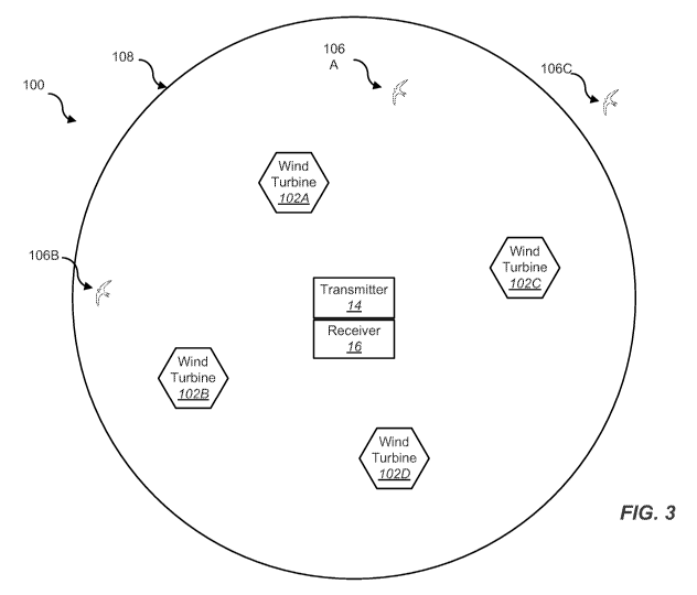
[0024] FIG. 3 is a schematic diagram of a wind-turbine tracking system in
accordance with the present disclosure.
5
CA 02814347 2013-04-10
WO 2012/054313
PCT/US2011/056227
[0025] FIG. 4 is a schematic diagram showing another example wind turbine
tracking system in accordance with the present disclosure.
[0026] FIG. 5 is a schematic diagram of an example road tracking system in
accordance with the present disclosure.
[0027] FIG. 6 is a schematic diagram showing an example balloon tracking
system for determining wind speed in accordance with the present disclosure.
[0028] FIG. 7 is a flow diagram showing steps of an example method in
accordance with the present disclosure.
[0029] FIG. 8 is a flow diagram showing steps of another example method in
accordance with the present disclosure.
[0030] FIG. 9 depicts a block diagram of a computer system suitable for
implementing the present systems and methods.
[0031] FIG. 10 is a block diagram depicting a network architecture in which
client systems, as well as storage servers (any of which can be implemented
using
computer system), are coupled to a network.
[0032] While the embodiments described herein are susceptible to various
modifications and alternative forms, specific embodiments have been shown by
way
of example in the drawings and will be described in detail herein. However,
the
exemplary embodiments described herein are not intended to be limited to the
particular forms disclosed. Rather, the instant disclosure covers all
modifications,
equivalents, and alternatives falling within the scope of the appended claims.
BEST MODE(S) FOR CARRYING OUT THE INVENTION
[0033] The present disclosure is directed to a method for locating moving
objects using a radar or radio fence. It is contemplated that the systems and
methods
of the present disclosure could be used for bird and bat species, to track
individual
animals or objects near wind farm turbines, or to track near other industrial
equipment that might be detrimental to an animal of interest, including high
voltage
transmission and distribution lines, substations and other distribution
equipment, and
power generation stations. In addition, it also contemplated that the systems
and
methods of the present disclosure could be used to track ground based mammals
and
reptiles for similar reasons such as avoidance and early detection of large
animals on
roadways passing through natural habitat or migration pathways, or detection
and
6
CA 02814347 2013-04-10
WO 2012/054313
PCT/US2011/056227
avoidance of animals dangerous to persons. Furthermore, the systems and
methods
disclosed herein could be used to perform general functions of interest to
field
biologists and meteorologists by attaching a passive tag or unpowered active
tag to
small balloons for the purpose of characterizing the vertical wind profile as
it rises.
It is contemplated further that the systems and methods disclosed herein could
be
used to discriminate authorized personnel or vehicles at a secure facility
from
unauthorized personnel or vehicles. It is further contemplated that the
systems and
method disclosed herein could be used for maritime use, to identify authorized
vessels, and many other uses.
[0034] In one example, a tracking system uses a passive tag for attachment to
wildlife or other object in question to help determine proximity of the
wildlife or
other object to a reference point. The tag may be lightweight and requires no
battery
or other energy storage device, and may remain on the wildlife or object
indefinitely.
The tag may be designed to be used in cooperation with radar or a radio field
'fence'
that allows the tag to, for example, return a detectable signal that helps
identify the
wildlife or object that has been previously tagged.
[0035] Two primary embodiments of this tag are described herein: 1) a
passive harmonic radar tag, and 2) an unpowered active tag. In one example, a
tagged bird is scanned by radar associated with a wind farm, or encounters a
radio
field 'fence' near a wind farm. The radar or radio field is emitted at a first
frequency. When the tagged bird moves into the radar or radio field, a passive
harmonic tag will receive the first frequency and re-radiate energy at a
different
second frequency. In one example, the second frequency is about twice the
first
radar frequency. When an unpowered active tag encounters a radar or radio
field,
the unpowered active tag uses energy derived from the radar or radio field to
power
an active return signal (e.g., a "blip") that identifies the tagged bird as a
previously
tagged object. The active return signal may carry information that identifies
the
tagged bird.
[0036] The system may include capabilities to determine relative location
between the tag carried by the wildlife (i.e., bird or animal) and a reference
point
such as, for example, a wind turbine or road. The system may also be operable
to
send a command signal to one or more mitigation devices such as, for example,
a
braking system for a wind turbine, or a road block or traffic light for a
road. The
7
CA 02814347 2013-04-10
WO 2012/054313
PCT/US2011/056227
system may be configured to perform other functions and operations in response
to
determining a location of the tag.
[0037] Referring now to FIG. 1, an example tracking system 10 is shown and
described. The tracking system includes a tracking device 12, a transmitter
14, a
receiver 16, a controller 18, and a plurality of mitigation devices 22A-D. The
tracking device 12 is carried by, for example, a wildlife or other object such
as a
weather balloon as described below. The tracking device 12 may include any one
of
the tags described above including, for example, a passive harmonic radar tag
or an
unpowered active tag. Typically, the tracking device 12 is mobile and the
tracking
system 10 is operable to determine a location of the tracking device relative
to a
reference point.
[0038] The transmitter 14 is configured to transmit a signal such as a radar
or
radio signal that produces an energy field (also referred to as a radar or
radio field)
having a frequency. The tracking device 12 responds to the signal sent by the
transmitter 14 and produces a responsive signal that is received by the
receiver 16.
The receiver 16 may include a number of modules as described below with
reference
to FIG. 2 to help determine a location of the tracking device 12. The receiver
16
may generate a command signal or other instructions for use by the controller
18.
The controller 18 may control the plurality of mitigation devices 22A-D via
any
desired communication such as, for example, via a network 20. The network 20
may
comprise a wired or wireless communication between the controller 18 and
mitigation devices 22A-D.
[0039] In one example, the tracking device 12 includes a passive harmonic
radar tag that includes a plurality of dipole antenna in a passive harmonic
radar
configuration. The passive harmonic radar tag is configured to capture and re-
radiate enough energy to provide a signal that is detectable within a desired
range of
distances. A cross dipole system may be employed to allow signal reactivity in
multiple orientations of the tag. Passive harmonic radar tags may include a
plurality
of antenna that are oriented orthogonal to each other, such that regardless of
the
orientation of the tag, at least one antenna element will be oriented
orthogonal to the
direction of flux from the radar or radio transmitter. In one example, the
desired
predetermined distance is in the range of about 0 to 10 miles, more preferably
in the
range of about 0 to about 1 mile, more preferably in the range of about 0 to
400
8
CA 02814347 2013-04-10
WO 2012/054313
PCT/US2011/056227
meters, which may be a preferable distance to detect a large bird such as a
golden
eagle in proximity to a wind turbine, or to allow sufficient time to slow the
spinning
wind turbine blades, if required. In some embodiments, the predetermined
distance
may be in the range of about 0 to 100 meters, which may be a preferable
distance
when there is a need to warn approaching cars of wildlife such as reindeer,
elk, or
other large animals in proximity to a road or highway.
[0040] A tracking device 12 may comprise a half-wave dipole resonant radar
tag micro strip or patched antennas. One function of the antennas is to
capture the
maximum amount of power from the radar or radio field and deliver as much of
that
power as possible to a nonlinear diode element. The use of lower radar or
radio
frequencies results in longer antennas, which may be preferable in certain
circumstances, as the lower radar frequencies and resulting longer antennas
allow
signals to penetrate woods and undergrowth more efficiently. For example, the
use
of typical X band marine radars for this purpose may require passive harmonic
antenna lengths of about 1.25 cm to 1.9 cm in length, but the signal from this
antenna would degrade in the presence of trees and undergrowth. An L band
radar
may require passive harmonic antenna lengths of about 7.5 cm to 15 cm in
length,
but would penetrate plant growth much better. It is contemplated that the
physical
antenna size may be smaller if the antenna is coiled in the manner of common
patch
antennas, at some loss of return signal.
[0041] An optimum radar frequency and antenna length may be adjusted for
such requirements as length of use for the tag, the size or shape of the
object
carrying the tag, and expected environmental conditions. In one example, a
center-
fed, half wavelength resonant dipole provides a broad, single lobe directivity
pattern
with maximum gain perpendicular to the antenna. The broad lobe construction
minimizes performance deprivation typically caused by rotation from a vertical
orientation, although dipole of different orientations may be used to
compensate for
such orientation issues.
[0042] A secondary function of the antennas is to collect from the diode as
much power as possible at a second harmonic frequency, and radiate this power
in a
horizontal direction and uniformly in azimuth. In one example, a separate
antenna,
optimized for this function, may be used with the tag. However, if biological
considerations or other characteristics of the object carrying the tag
outweigh the
9
CA 02814347 2013-04-10
WO 2012/054313
PCT/US2011/056227
importance of optimizing range, then the same dipole may be used to return the
signal. In one example, a low barrier Schottky diode may be used as the
nonlinear
element for a transponder of the tag because of intrinsic low junction
capacitances
that reduces signal loss at high frequency and its low barrier allows the
diode to be
turned on by very low induced voltages. It is contemplated that the secondary
or
return antenna of the tag may be tuned slightly differently for each tag,
allowing a
positive identification of a particular bird or other object carrying the tag.
[0043] Passive harmonic radar tags may be relatively light weight, such as,
for
an example, in the range of 10 milligrams to 10 grams. In one example, the
passive
harmonic radar tag has a weight of less than 1 gram, a weight of no more than
5
grams, or a weight of no more than 10 grams.
[0044] An unpowered tag for use as the tracking device 12 may supply a
signal "blip" when energized by an exterior power source such as the radar or
radio
energy field produced by the transmitter 14. The unpowered tag may or may not
include identification information such as a particular bird identifier or
other
information about the object being tracked. The tag may be constructed and
operable without the use of a battery or other long-term energy storage
source. The
tag may include a rectenna or similar device that collects radio or radar
energy from
the transmitter, and transforms the energy into direct current voltage that is
used to
power the active portion of the tag.
[0045] A rectenna is typically classified as a rectifying antenna that
directly
converts energy (e.g., microwave, radar, or radio energy) into DC electricity.
A
rectenna typically includes elements that are arranged in a multi-element
phase with
a mesh pattern reflective element that provides directionality. The simplest
rectenna
may be constructed from a Schottky diode placed between antenna dipoles,
wherein
the dipoles are sized to the resonant frequency of the available
radar/radio/microwave energy. Schottky diodes may be preferred because they
have
the lowest voltage drop and highest speed, and therefore waste the least
amount of
power due to conduction and switching. Rectennas are typically highly
efficient in
converting energy (radar/microwave/radio) to electricity (e.g., efficiencies
in the
range of up to 90 percent).
[0046] One type of tag that may be used as the tracking device 12 is known as
a VHF pulse tag that sends out periodic pulses of radio signal that can be
located
CA 02814347 2013-04-10
WO 2012/054313
PCT/US2011/056227
with a specialized VHF receiver. An example in accordance with the present
disclosure includes the use of a rectenna to provide power for the VHF pulse
function that would then be received by the receiver 16 to assist in
mitigating
damage to the wildlife or other object that carries the tracking device 12.
[0047] In one example, as the wildlife or other object carrying the tracking
device 12 approaches an object (e.g., a wind turbine or road), the tracking
system 10
identifies that the tracking device 12 is approaching the object. The tracking
system
may operate to identify whether the wildlife or other object carrying the
tracking
device 12 has been previously tagged or can be identified in some other way.
At this
10 time, a decision may be made either automatically by the tracking system
10 (e.g.,
by the receiver 16 and/or controller 18) or manually by an operator as to
whether a
mitigation action should be taken via one of the mitigation devices 22A-D. In
one
example, the mitigation action is reducing a rotation speed of a wind turbine
using
one of mitigation devices 22A-D. In other examples, the mitigation devices 22A-
D
comprise a deterrent system such as a flashing light, audible noise, repulsive
smell,
or other deterrent that helps change the path of the wildlife or other object
carrying
the tracking device 12.
[0048] The transmitter 14 may be configured to transmit a radar, radio, or
other type of signal that activates or is otherwise used by the tracking
device 12 to
create a responsive signal by the tracking device 12 that can be detected by
the
receiver 16. In one example, radars may be transmitted by the transmitter 14
to
create a zone or field (e.g., an energy field) in proximity a reference point
such as,
for example, an object or structure that poses a danger to a wildlife. FIG. 3
illustrates a wind turbine system 100 that includes a plurality of wind
turbines 102A-
D and an energy field 108 created around the wind turbines 102A-D by the
transmitter 14. The energy (e.g., radar or radio signal) within the energy
field 108
may activate one or more tracking devices carried by birds 106A-C (e.g., a
wildlife).
Once the birds 106A-C are positioned within the energy field 108, the tracking
devices 112 carried by the birds 106A-C may be detected by receiver 16 and
tracked
relative to any one of the wind turbines 102A-D.
[0049] In one example, the transmitter 14 produces frequency modulated
continuous wave (FMCW) radars that emit a steady stream of electromagnetic
radiation. The system 100 tracks the birds 106A-C by modulating the
transmission
11
CA 02814347 2013-04-10
WO 2012/054313
PCT/US2011/056227
frequency of the radar via the transmitter 14 and comparing the frequency of
outgoing signals from the transmitter 14 to returning signals at the receiver
16
received from the tracking devices 12 carried by the birds 106A-C.
[0050] This process using the FMCW radars may limit the need for high peak
transmitted power while offering higher precision in the measurement of
distance or
range of the birds 106A-C. In one example, the radar emitted from transmitter
14
includes a pulse radar, which emits short, discreet bursts of high power
radiation.
The birds 106A-C carrying tracking devices 12 may be tracked using a time
lapse
between transmission of a signal via transmitter 14 and reception of a return
signal
from the tracking device 12 via receiver 16. These types of radars may provide
production, durability, and cost advantages as compared to FMCW radars. In one
example, a pulse radar transmitter provides a high-peak power that increases a
harmonic conversion at the tag of the tracking device, and thereby provides
for a
better harmonic return signal to the receiver 16.
[0051] The transmitter 14 may include, for example, a 9.4 GHz transmitter.
The receiver 16 may include, for example, an 18.8 GHz receiver. In some
arrangements a lower frequency for at least one of the transmitter 14 and
receiver 16
may be preferred if the antenna length for the tag of the tracking device 12
does not
interfere with the wildlife or other object that carries the tracking device
12. In a
passive harmonic radar tag system, it may be useful to have both the
transmitting
and receiving antenna carefully aligned so that the transmission and reception
beams
will be closely co-linear over a planned working range. For an unpowered
active
system, the receiver 16 may be positioned at a location that is not coincident
with
other features of the system 100 such as, for example, the transmitter 14.
[0052] In FIG. 3, any one of the birds 106A-C may be detected with the
system 100 depending on, for example, whether the bird 106A-C is carrying a
tracking device and whether or not the bird 106A-C is positioned within the
energy
field 108. Once the system 100 identifies the bird 106A-C (i.e., within the
energy
field 108), the system 100 may track movement of the bird 106A-C relative to
any of
the wind turbines 102A-D. A travel path of each bird 106A-C may be determined
using, for example, software algorithms or manually by an operator. The system
100
may automatically undertake a risk assessment as to whether or not any of the
birds
106A-C will approach any one of the wind turbines 102A-D given its current
flight
12
CA 02814347 2013-04-10
WO 2012/054313
PCT/US2011/056227
path. A number of factors may be considered before activating one of the
mitigation
devices of system 100 (e.g., slowing down the rotation of the wind turbines),
including, for example, the type of bird, the size of the bird, the flight
speed of the
bird, and a current condition of the wind turbine (e.g., rotation speed of the
wind
turbine). Based on any one of these or other factors, a system 100, either
automatically or by manual activation generates a command control that is
delivered
to one or more mitigation devices to limit or reduce danger to the bird.
[0053] The system 100 shown in FIG. 3 includes a single energy field 108
associated with a plurality of wind turbines 102A-D. In other examples, a
single
energy field 108 generated by one or more transmitters 14 may be associated
with
each individual wind turbine 102A-D. Similarly, a single receiver 16 may be
associated with each individual transmitter or wind turbine 102A-D.
[0054] Referring to FIG. 2, the receiver 16 may include a receiver module 30.
The receiver module 30 may include a plurality of subcomponents or modules
operable to provide desired functionality for the receiver 16 and the related
tracking
systems disclosed herein. The receiver module 30 may include a locating module
32, an antenna module 34, a decision module 36, and a command module 38. The
locating module 32 may function to identify a location of the tracking device
from
which the receiver receives a signal. The locating module 32 may identify
relative
location between the tracking device and the receiver 16 as well as determine
a
location of the tracking device relative to other objects such as an object of
danger
(e.g., a wind farm or highway), the transmitter 14 or other reference point.
[0055] The antenna module 34 may collect or receive signals from a tracking
device. The antenna module 34 may route the incoming signals to other modules
of
the receiver module 30.
[0056] The decision module 36 may be operable to collect information from
the other modules of the receiver module 30 such as, for example, a location
of the
tracking device 12, information about the tracking device and the wildlife or
object
that carries the tracking device (e.g., travel speed and physical properties
of the
wildlife), a time of day, weather and other information to decide whether to
initiate
some mitigation that would reduce danger.
[0057] The command module 38 is operable to deliver a command signal such
as instructions from the receiver module 30 to the controller 18. The command
13
CA 02814347 2013-04-10
WO 2012/054313
PCT/US2011/056227
module 38 may include commands that are passed through the controller 18 and
through the network 22 to the mitigation devices 22A-D (see FIG. 1). In other
arrangements, the command module 38 conveys data or other information that may
be used by the controller 18 to formulate a command or instruction for use by
the
mitigation device 22A-D. In other arrangements, the command module 38 may
generate signals that bypass the controller 18 and are used directly by the
mitigation
device 22A-D.
[0058]Referring to FIG. 4, another example wind turbine tracking system 200
is shown. The wind turbine tracking system 100 includes a plurality of
transmitters
14A-F creating a plurality of energy fields or zones 208A-F in proximity to
one or
more wind turbines 102. A receiver 16 may be positioned in proximity to one or
more of the transmitters 14A-F, for example, at a location central to the
transmitters
14A-F. The system 200 may help identify a bird or other wildlife 106A-C using
a
combination of radar or radio signals to create a plurality of energy fields
208A-F
and a tag carried by the birds 106A-C. The tag may be part of a tracking
device
carried by one or more of the bird 106A-C, and is configured to absorb radar
or radio
energy from the energy fields 208A-F and either reflect back a signal of a
different
frequency (e.g., via a passive harmonic tag), or utilize the received energy
to power
a device that broadcasts an active signal that is detectable by the receiver
16. Any
signals reflected or generated by the tracking device carried by the bird 106A-
C may
include identification information for the bird or other object to which the
tracking
device is mounted.
[0059]In one example, in which the tag is unpowered, the tracking device
carried by the wildlife or other object may have an indefinite life expectancy
with a
relative low failure rate because it is operable without the use of a separate
power
source (e.g., battery). Such tags may also be relatively lightweight as
compared to
tags that carry a separate power source. Such tags may also limit the need to
retag
the wildlife or other object carrying the tracking device due to the longer
lifetime
possible given the technologies for the tag discussed and disclosed herein.
[0060]Referring now to FIG. 5, a road tracking system 300 is shown. The
road tracking system 300 includes a road 302 that may be referenced as an
object or
area of danger for wildlife 310A-D. Wildlife 310A-D may be situated at any
location relative to the road 302. A plurality of transmitters 14A-B may be
used to
14
CA 02814347 2013-04-10
WO 2012/054313
PCT/US2011/056227
create energy fields 308A-B in proximity to the road 302. When the wildlife
310A-
D moves into the energy fields 308A-B, tracking devices carried by the
wildlife
310A-D may be activated in some way to create a return signal receptive by
receiver
16. Receiver 16 may function using, for example, receiver module 30 described
above, to initiate one or more mitigating acts, such as, for example,
operating a road
block 304 or a traffic light 306 that warns drivers on the road 302 as to the
presence
of wildlife 310A-D, or operating a sound or light generating device that
scares away
the wildlife.
[0061] The road tracking system 300 may be most relevant to larger animals
such as, for example, deer, elk, moose, bear, and antelope. However, the
system 300
may also be used for smaller animals such as, for example, badgers, raccoons,
or
other wildlife such as reptiles or birds. System 300 may be also be useful for
tracking and protecting domesticated animals such as bovines and equines that
are
sometimes grazing an open range lands with little or no physical barriers
between
them and the road 302.
[0062] The tracking device 12 carried by wildlife 310A-D may include a tag
that is attached to the animals via any desired tagging system or method. Some
types of tagging systems may reduce potential harm to the wildlife to which
the tag
is mounted and limit physical contact between the wildlife and those applying
the
tag. In one example, a tagging campaign may focus on applying tags to a few
animals or birds in a large herd or flock of the wildlife that may be in
proximity to
the road 302. In other examples, a tagging campaign may focus on large
breeding
males and mature females of a herd with the expectation that the remainder of
the
herd will normally follow along with the dominant herd members.
[0063] As compared to existing animal tags and tagging methods, the tags and
tagging systems disclosed herein may, in at least some examples, be deployed
rapidly with minimal impact to the wildlife. For example, due to the
relatively small
size of the tag and lack of moving parts or power requirements, it is
envisioned that
an air powered gun or similar device may fire the tag at the animal. The tag
may be
positioned within an adhesive glue ball or other structure that is constructed
to
attach to the hair, skin or fur of a given wildlife.
[0064] Referring now to FIG. 6, another example system utilizing the tracking
feature disclosed herein is described. FIG. 6 shows a balloon tracking system
400
CA 02814347 2013-04-10
WO 2012/054313
PCT/US2011/056227
that may be used in the field of atmospheric physics for measuring a vertical
profile
of wind speeds at a given geographical location. A wind speed profile obtained
using the balloon tracking system 400 may be useful in a number of
applications
including, for example, weather models, pollution disbursement modules, air
traffic
control and resource analysis for wind farms.
[0065] Commonly used technologies for measuring wind speed include
LIDAR (light detection and ranging), SODAR (sonic detection and ranging),
balloons and meteorological towers instrumented with anemometers. LIDAR uses
laser pulses that scatter off of atmospheric aerosols and return to the
instrument. By
computing a Doppler shift between the outgoing frequency and return frequency,
the
wind speed may be calculated at various heights. Most current LIDAR systems
are
limited to measurements of less than 300 meters above ground level. SODAR
works
using a similar principle as LIDAR, except that sound pulses are used instead
of
lasers. Most current SODAR systems are limited to measurements of less than
300
meters above ground level. Instrument towers may involve the erection of a
tubular
or lattice tower outfitted with anemometers at various heights. Such towers
are
typically limited to about 60 meters in height.
[0066]Application of the tracking system features disclosed herein (i.e., a
passive tag) attached to a balloon may provide an alternative to the LIDAR,
SODAR
and meteorological tower instruments with anemometers described above. As
shown
in FIG. 6, a passive tag, which is part of tracking device 12, may be carried
by a
balloon 402. Wind W1 moves the balloon 402 to an angle 13 relative to a
vertical
plane. The receiver 16 may operate to determine a speed of the wind W1 based
on a
number of factors including a relative position of the balloon 402 to a
reference
point (e.g., a position of the receiver 16) determined by signals transmitted
by the
tracking device 12.
[0067] The balloon 402 may be released from ground level, and the signal
return from the tracking device 12 is used to compute the relative position of
the
balloon as it floats away unattached. Using established mathematic equations,
a
software algorithm may compute the speed of the wind W1 based on the relative
position of the tagged balloon as it floats upward into the atmosphere,
yielding the
current wind speed as a function of height relative to a reference point on
the
ground. It may be advantageous to use this kind of approach rather than
existing
16
CA 02814347 2013-04-10
WO 2012/054313
PCT/US2011/056227
methodologies due to the relative low cost nature of the tag and the
propensity for
nonrecovery of weather balloon components. Also, traditional radar systems may
rely on the size, shape and orientation of the radar cross-section to get a
new return
signal. With the passive harmonic tags system noted herein, the return
frequency is
typically twice the transmission frequency. The tag typically will be the only
object
radiating at that frequency within the range of the receiving antenna. This
allows for
an extremely high discrimination of the tagged balloon against the background,
and
allows the radar to detect the balloon tag at relatively long ranges, outside
the
typical ranges of LIDAR, SODAR, and large radar ranging balloons, and at a
much
lower cost than typical battery powered radiosonde devices containing
meteorological instruments.
[0068] Referring now to FIG. 7, an example method 500 in accordance with
one aspect of the present disclosure is disclosed. In a first step 502, the
method
includes providing a transmitter, a receiver, a controller, and a tracking
device. The
tracking device is mounted to a wildlife. In a second step 504, the system
generates
an energy field with the transmitter. In a step 506, the tracking device
generates a
signal when the wildlife enters the energy field. In a step 508, the signal is
received
at the receiver. The method also includes determining a location of the
wildlife
relative to a reference point in a step 510. If the wildlife is within a
predetermined
distance of the referenced point, a signal is delivered to the controller and
the
command is generated with the controller to mitigate danger for the wildlife
in a step
510. Alternative methods may include more or fewer steps as compared to those
of
method 500.
[0069] Referring to FIG. 8, another example method 600 includes generating
an energy field that activates a tracking device to generate a signal, wherein
the
tracking device is mounted to a wildlife in a step 602. Next, in a step 604,
signals
are received from the tracking device. A location of the wildlife is
determined
relative to a reference point in a step 606. A command signal is delivered to
a
device that is operable to reduce danger for the wildlife and the location of
the
wildlife is within a predetermined distance from the reference point in a step
608.
Alternative methods may include more or fewer steps as compared to those of
method 600.
17
CA 02814347 2013-04-10
WO 2012/054313
PCT/US2011/056227
[0070] FIG. 9 depicts a block diagram of a computer system 810 suitable for
implementing the present systems and methods. Computer system 810 includes a
bus 812 which interconnects major subsystems of computer system 810, such as a
central processor 814, a system memory 817 (typically RAM, but which may also
include ROM, flash RAM, or the like), an input/output controller 818, an
external
audio device, such as a speaker system 820 via an audio output interface 822,
an
external device, such as a display screen 824 via display adapter 826, serial
ports
828 and 830, a keyboard 832 (interfaced with a keyboard controller 833),
multiple
USB devices 892 (interfaced with a USB controller 890), a storage interface
834, a
floppy disk drive 837 operative to receive a floppy disk 838, a host bus
adapter
(HBA) interface card 835A operative to connect with a Fibre Channel network
890,
a host bus adapter (HBA) interface card 835B operative to connect to a SCSI
bus
839, and an optical disk drive 840 operative to receive an optical disk 842.
Also
included are a mouse 846 (or other point-and-click device, coupled to bus 812
via
serial port 828), a modem 847 (coupled to bus 812 via serial port 830), and a
network interface 848 (coupled directly to bus 812).
[0071] Bus 812 allows data communication between central processor 814 and
system memory 817, which may include read-only memory (ROM) or flash memory
(neither shown), and random access memory (RAM) (not shown), as previously
noted. The RAM is generally the main memory into which the operating system
and
application programs are loaded. The ROM or flash memory can contain, among
other code, the Basic Input-Output system (BIOS) which controls basic hardware
operation such as the interaction with peripheral components or devices. For
example, the receiver module 30 to implement the present systems and methods
may
be stored within the system memory 817. Applications resident with computer
system 810 are generally stored on and accessed via a non-transitory computer
readable medium, such as a hard disk drive (e.g., fixed disk 844), an optical
drive
(e.g., optical drive 840), a floppy disk unit 837, or other storage medium.
Additionally, applications can be in the form of electronic signals modulated
in
accordance with the application and data communication technology when
accessed
via network modem 847 or interface 848.
[0072] Storage interface 834, as with the other storage interfaces of computer
system 810, can connect to a standard non-transitory computer readable medium
for
18
CA 02814347 2013-04-10
WO 2012/054313
PCT/US2011/056227
storage and/or retrieval of information, such as a fixed disk drive 844. Fixed
disk
drive 844 may be a part of computer system 810 or may be separate and accessed
through other interface systems. Modem 847 may provide a direct connection to
a
remote server via a telephone link or to the Internet via an internet service
provider
(ISP). Network interface 848 may provide a direct connection to a remote
server via
a direct network link to the Internet via a POP (point of presence). Network
interface 848 may provide such connection using wireless techniques, including
digital cellular telephone connection, Cellular Digital Packet Data (CDPD)
connection, digital satellite data connection or the like.
[0073] Many other devices or subsystems (not shown) may be connected in a
similar manner (e.g., document scanners, digital cameras and so on).
Conversely, all
of the devices shown in FIG. 9 need not be present to practice the present
systems
and methods. The devices and subsystems can be interconnected in different
ways
from that shown in FIG. 9. The operation of a computer system such as that
shown
in FIG. 9 is readily known in the art and is not discussed in detail in this
application.
Code to implement the present disclosure can be stored in a non-transitory
computer-
readable medium such as one or more of system memory 817, fixed disk 844,
optical
disk 842, or floppy disk 838. The operating system provided on computer system
810 may be MS-DOS , MS-WINDOWS , OS/2 , UNIX , Linux , or another known
operating system.
[0074] Moreover, regarding the signals described herein, those skilled in the
art will recognize that a signal can be directly transmitted from a first
block to a
second block, or a signal can be modified (e.g., amplified, attenuated,
delayed,
latched, buffered, inverted, filtered, or otherwise modified) between the
blocks.
Although the signals of the above described embodiment are characterized as
transmitted from one block to the next, other embodiments of the present
systems
and methods may include modified signals in place of such directly transmitted
signals as long as the informational and/or functional aspect of the signal is
transmitted between blocks. To some extent, a signal input at a second block
can be
conceptualized as a second signal derived from a first signal output from a
first
block due to physical limitations of the circuitry involved (e.g., there will
inevitably
be some attenuation and delay). Therefore, as used herein, a second signal
derived
from a first signal includes the first signal or any modifications to the
first signal,
19
CA 02814347 2013-04-10
WO 2012/054313
PCT/US2011/056227
whether due to circuit limitations or due to passage through other circuit
elements
which do not change the informational and/or final functional aspect of the
first
signal.
[0075] FIG. 10 is a block diagram depicting a network architecture 900 in
which client systems 910, 920 and 930, as well as storage servers 940A and
940B
(any of which can be implemented using computer system 910), are coupled to a
network 950. In one embodiment, the receiver module 30 may be located within a
server 940A, 940B to implement the present systems and methods. The storage
server 940A is further depicted as having storage devices 960A(1)-(N) directly
attached, and storage server 940B is depicted with storage devices 960B(1)-(N)
directly attached. SAN fabric 970 supports access to storage devices 980(1)-
(N) by
storage servers 940A and 940B, and so by client systems 910, 920 and 930 via
network 950. Intelligent storage array 990 is also shown as an example of a
specific
storage device accessible via SAN fabric 970.
[0076] With reference to computer system 810, modem 847, network interface
848 or some other method can be used to provide connectivity from each of
client
computer systems 910, 920, and 930 to network 950. Client systems 910, 920,
and
930 are able to access information on storage server 940A or 940B using, for
example, a web browser or other client software (not shown). Such a client
allows
client systems 910, 920, and 930 to access data hosted by storage server 940A
or
940B or one of storage devices 960A(1)-(N), 960B(1)-(N), 980(1)-(N) or
intelligent
storage array 990. FIG. 10 depicts the use of a network such as the Internet
for
exchanging data, but the present systems and methods are not limited to the
Internet
or any particular network-based environment.
[0077] While the foregoing disclosure sets forth various embodiments using
specific block diagrams, flowcharts, and examples, each block diagram
component,
flowchart step, operation, and/or component described and/or illustrated
herein may
be implemented, individually and/or collectively, using a wide range of
hardware,
software, or firmware (or any combination thereof) configurations. In
addition, any
disclosure of components contained within other components should be
considered
exemplary in nature since many other architectures can be implemented to
achieve
the same functionality.
CA 02814347 2013-04-10
WO 2012/054313
PCT/US2011/056227
[0078] The process parameters and sequence of steps described and/or
illustrated herein are given by way of example only and can be varied as
desired.
For example, while the steps illustrated and/or described herein may be shown
or
discussed in a particular order, these steps do not necessarily need to be
performed
in the order illustrated or discussed. The various exemplary methods described
and/or illustrated herein may also omit one or more of the steps described or
illustrated herein or include additional steps in addition to those disclosed.
[0079] Furthermore, while various embodiments have been described and/or
illustrated herein in the context of fully functional computing systems, one
or more
of these exemplary embodiments may be distributed as a program product in a
variety of forms, regardless of the particular type of computer-readable media
used
to actually carry out the distribution. The embodiments disclosed herein may
also be
implemented using software modules that perform certain tasks. These software
modules may include script, batch, or other executable files that may be
stored on a
computer-readable storage medium or in a computing system.
In some
embodiments, these software modules may configure a computing system to
perform
one or more of the exemplary embodiments disclosed herein.
[0080] The foregoing description, for purpose of explanation, has been
described with reference to specific embodiments.
However, the illustrative
discussions above are not intended to be exhaustive or to limit the invention
to the
precise forms disclosed. Many modifications and variations are possible in
view of
the above teachings. The embodiments were chosen and described in order to
best
explain the principles of the present systems and methods and their practical
applications, to thereby enable others skilled in the art to best utilize the
present
systems and methods and various embodiments with various modifications as may
be
suited to the particular use contemplated.
[0081]Unless otherwise noted, the terms "a" or "an," as used in the
specification and claims, are to be construed as meaning "at least one of." In
addition, for ease of use, the words "including" and "having," as used in the
specification and claims, are interchangeable with and have the same meaning
as the
word "comprising."
21