Note: Descriptions are shown in the official language in which they were submitted.
DOUBLE HUNG OPERATION HARDWARE
TECHNICAL FIELD
This document pertains generally, but not by way of limitation, to
fenestration operation hardware.
BACKGROUND
Tilt latches are used with some examples of double hung windows to
facilitate the tilting of the window sashes. Tilting of the window sashes
allows for
cleaning of the interior and exterior of the window sash while the operator is
located, for instance, indoors. In at least some examples, tilt latches are
actuated by
the operator by applying hand pressure to tilt latches that are otherwise
biased
outwardly into the adjacent jambs. Actuation of the tilt latches allows for
tilting of
the window sash.
In some examples, the operator must simultaneously actuate each of two tilt
latches installed on opposite sides of the window sash to enable tilting of
the sash.
The tilt latches must be individually operated and held in a retracted
orientation to
permit tilting. In other words, the tilt latches are biased into the projected
orientation when released, and it is correspondingly difficult to actuate each
of the
tilt latches while tilting the sash at the same time.
1
CA 2814416 2019-08-12
CA 02814416 2013-04-30
Additionally, at least some examples of tilt latches are located in the center
on the bottom check rail. This location coincides with the center of the
balance
tube. Such an arrangement limits the engagement available for the latch within
the
jamb and hinders structural performance (e.g., security and wind load).
Additionally, tilt latches in this location limits the size of sash balances.
Further, where tilt latches are incorporated within a bottom check rail a
pocket is created in the check rail that spans the slot and tenon joints to
permit
housing of the tilt latch and the components associated with the tilt latch
including,
but not limited to, the latch housing, the tilt latch bolt, a spring to bias
the tilt latch
bolt, pins or slides for finger or hand actuation, access orifices to reach
the pins or
slides and the like. This arrangement compromises the strength of the joints.
OVERVIEW
The present inventors have recognized, among other things, that a problem
to be solved can include eliminating redundant hardware used in separate
mechanisms for operating tilt mechanisms and locking and unlocking of sashes
for
movement within a frame. In an example, the present subject matter can provide
a
solution to this problem, for instance with an operation hardware assembly
that
remotely actuates latch bolts to lock and unlock a sash for sliding movement
within
a frame and also further actuate the latch bolts to permit tilting of the
sash. The
operation hardware assembly consolidates tilting and locking/unlocking
functions
into a single assembly that is actuated with an operator, such as a rotatable
handle.
Separated and independently operated hardware including rotating sweeps with
keepers and tilt latches are thereby avoided.
Further, the operation hardware assembly examples described herein are
usable to independently lock and unlock top and bottom sashes without sweeps
and
keepers extending between opposed check rails. In one example, the bottom sash
is
locked relative to the frame with the latch bolts actuated through an
operator, such
as a rotatable handle. The latch bolts are received within corresponding
recesses in
2
Attorney Docket: 1261.158CAI
CA 02814416 2013-04-30
the frame, for instance jamb components including recesses sized and shaped to
receive the latch bolts. Optionally, the top sash includes its own latch bolts
that are
sized and shaped to fit within corresponding recesses and thereby
independently
lock the top sash in place. Alternatively, the latch bolts of the top and
bottom sashes
are cooperatively opened, for instance by selectively coupling the bolts at
the
interface of the check rails.
Further still, with jamb components including one or more of planar
surfaces, recesses and tapered features, the operation hardware assembly
including
the latch bolts provides additional functionality including, but not limited
to,
automatic locking of one or more of the sashes in the closed position, a
secure
venting position or any other positions within the range of movement for the
sash,
positioning of the bottom sash in a secure vent position (e.g., with the
bottom of the
bottom sash at around 4 inches above the sill), and even function of the
operation
hardware assembly as a window opening control device to allow for limited
opening
of the sashes to a specified elevation.
Furthermore, as described herein in at least some examples, with the
operation hardware assembly married with recesses in the frame that allow for
locking through the latch bolts, sweeps and keepers adjacent to the operator
are not
needed. In other examples, where added security is desired a sweep and keeper
may
be included with the operator and the opposed checkrail to provide additional
locking of the sashes. In still other examples, where a tapered recess or
engagement
surface is provided that allows for sliding of the latch bolts from the locked
position
a sweep and keeper are incorporated into the operation hardware to ensure
secure
locking of the sashes in the closed position.
This overview is intended to provide an overview of subject matter of the
present patent application. It is not intended to provide an exclusive or
exhaustive
explanation of the invention. The detailed description is included to provide
further
information about the present patent application.
3
Attorney Docket: 1261.158CA1
CA 02814416 2013-04-30
BRIEF DESCRIPTION OF THE DRAWINGS
In the drawings, which are not necessarily drawn to scale, like numerals may
describe similar components in different views. Like numerals having different
letter suffixes may represent different instances of similar components. The
drawings illustrate generally, by way of example, but not by way of
limitation,
various embodiments discussed in the present document.
Figure 1 is front view of one example of a fenestration assembly.
Figure 2A is a cross sectional view of the fenestration assembly shown
in
Figure 1 including one example of an operation hardware
assembly installed within a sash.
Figure 2B is a detailed cross sectional view of a sash used with the
fenestration assembly including the operation hardware assembly
shown in Figure 1.
Figure 3 is an exploded view of the operator shown in Figures 2A, B.
Figure 4 is a perspective view of one example of a spool for use with the
operator shown in Figures 2A, B.
Figure 5 is a perspective view of one example of a detent for use
with the
operator shown in Figures 2A, B.
Figure 6 is a perspective view of one example of a cam fitting for
use with
the operator shown in Figures 2A, B.
Figure 7 is a perspective view of the assembled operator shown in
Figures
2A, B.
Figure 8 is a bottom view of the assembled operator shown in Figure
7.
Figure 9 is a cross sectional view of one example of a latch
mechanism
installed within a sash.
Figure 10 is an isometric view showing one example of a jamb component
of the operation hardware assembly.
Figure 11A is a cross sectional view of the jamb component shown in
Figure
10 showing a latch bolt received in a lower recess.
4
Attorney Docket: 1261.158CA1
CA 02814416 2013-04-30
Figure 11B is a cross sectional view of another example of a jamb
component
showing a latch bolt received in a lower recess.
Figure 11C is a cross sectional view of yet another example of a jamb
component with the latch bolt in a projecting position and the
sash in the closed position.
Figure 11D is a cross sectional view of the jamb component shown in
Figure
8C with the sash elevated into a secure venting position with the
latch bolt received within an upper recess.
Figure 12 is a cross sectional view of the jamb component shown in
Figures
11C, D with the latch bolt in a second withdrawn position that
permits tilting of the sash.
Figure 13A is a bottom view of the operator shown in Figures 7, 8 with
the
operator interface feature in a locked position.
Figure 13B is a bottom view of the operator shown in Figures 7, 8 with
the
operator interface feature in a first operating position.
Figure 13C is a bottom view of the operator shown in Figures 7, 8 with
the
operator interface feature in a second operating position and the
spool is rotated with the detent in a second detent recess.
Figure 13D is a bottom view of the operator shown in Figures 7, 8 with
the
operator interface feature in a third operating position and the
spool is further rotated with the detent in the third detent recess.
Figure 13E is a bottom view of the operator shown in Figures 7, 8 with
the
operator interface feature rotated in an opposed direction, and a
resetting cam is engaged with the detent.
Figure 14 is a schematic series of views depicting the position of a latch
bolt according to remote operation of the operator with a jamb
component as shown in Figure 11B.
5
Attorney Docket: 1261.158CA1
CA 02814416 2013-04-30
Figure 15 is a schematic series of views depicting the position of a
latch
bolt according to remote operation of the operator with a jamb
component as shown in Figure 11C.
Figure 16A is a cross sectional view of the fenestration assembly shown
in
Figure 1 including another example of an operation hardware
assembly installed within the sash.
Figure 16B is a detailed cross sectional view of the sash used with the
fenestration assembly including the operation hardware assembly
shown in Figure 16A.
Figure 17A is a perspective top view of an operator of the operation
hardware
assembly of Figure 16A.
Figure 17B is a perspective bottom view of the operator.
Figure 17C1, 2 are dual exploded views of the operator (top and bottom).
Figure 18A is a perspective bottom view of one example of a second
spool
and a plunger assembly.
Figure 18B is an exploded view of the second spool and the plunger
assembly of Figure 18A.
Figure 19 is a bottom view of a tying element extending through first
and
second spools.
Figure 20 is a perspective view of one example of one example of a detent
and a detent release.
Figure 21 is a perspective view of one example of a plunger.
Figure 22 is a perspective view of another example of a bottom latch
mechanism.
Figure 23 is a perspective view of one example of a paddle configured to
transmit rotation of one latch bolt to another latch bolt.
Figure 24 is a perspective view of another example of a top latch
mechanism.
6
Attorney Docket: 1261.158CAI
CA 02814416 2013-04-30
Figure 25 is a cross sectional view of the fenestration assembly
including
the operator shown in Figure 17A in an initial configuration with
the top and bottom panels closed.
Figure 26 is a bottom view of the operator in a first operating
configuration.
Figure 27A is a top view of the operator with the plunger in an extended
position.
Figure 27B is a cross sectional of the operator with the plunger in an
extended position.
Figure 28 is a bottom view of the operator of Figure 17A transitioning
to a
second operation configuration.
Figures 29A-C are bottom views of the operator of Figure 17A being reset.
Figure 30 is a perspective view of the operator of Figure 17A being
automatically reset to the orientation shown in Figure 25 through
closing of the top and bottom panels.
Figure 31 is a bottom view of the operator of Figure 30.
Figure 32A is a composite top view of the operator of Figure 17A with
the
operator interface feature in closed, first operating, second
operating and intermediate positions.
Figure 32B is a bottom view of the first and second spools as the
operator
interface feature is rotated from the first operating position to the
second operating position.
Figure 33 is an exploded view of one example of an operator interface
feature including a tilt transition feature.
Figure 34A is a perspective view of the operator interface feature of
Figure
33 in a first transitional position.
Figure 34B is a bottom perspective view of one example of the operator
including a stopping bar in the first transitional position.
Figure 35A is a perspective view of the operator interface feature of
Figure
33 in a second transitional position.
7
Attorney Docket: 1261.158CA1
CA 02814416 2013-04-30
Figure 35B is a bottom perspective view of one example of the operator
including a stopping bar in the second transitional position.
Figure 36A is a perspective view of the operator interface feature of
Figure
33 in the first operational position.
Figure 36B is a bottom perspective view of one example of the operator
including a stopping bar in the first operational position.
DETAILED DESCRIPTION
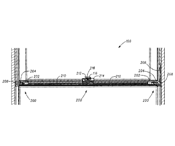
Figure 1 shows one example of a fenestration assembly 100 including, for
instance, a double hung window or sliding door. As shown the fenestration
assembly 100 includes a frame 102 surrounding one or more sashes such as a
bottom sash 104 and a top sash 106 as shown in Figure 1. In the example where
the
fenestration assembly 100 includes a double hung window, in one example, the
top
and bottom sashes 106, 104 include corresponding glass panes 108, 110. In one
example, at least one of the sashes such as the bottom sash 104 slidable
within the
frame 102, for instance, after unlocking the bottom sash 104 from a closed
position
as shown in Figure 1. In another example, both of the sashes 104, 106 are
movable
within the frame 102, for instance, after operation of an operator 116 as
described
herein. Optionally, sashes include panels, such as, but not limited to, door
panels
and the like.
Referring again to Figure 1, the fenestration assembly 100, for instance, the
bottom and top sashes 104, 106, in another example, include corresponding
bottom
and upper check rails 112, 114. As will be described in further detail herein,
the
operator 116 is, in one example, positioned within the bottom check rail 112
and is
configured to operate one or more locking mechanisms to selectively immobilize
and free at least the bottom sash 104 for sliding within the frame 102. In
another
example, an operator 116 is coupled or positioned along the upper check rail
114 of
the top sash 106. In such an example, the operator 116 coupled with the upper
check rail 114 is configured to operate in a similar manner to an operator
such as
8
Attorney Docket: 1261.158CA1
CA 02814416 2013-04-30
that shown in Figure 1 (e.g., operator 116) to selectively immobilize and free
the top
sash 106 for movement within the frame 102.
Referring now to Figures 2A and 2B the fenestration assembly 100
previously shown in Figure 1 is provided in cross section. As shown the
fenestration assembly 100 includes an operation hardware assembly 200
configured
to selectively immobilize and free the corresponding sashes such as the bottom
and
top sashes 104, 106 for sliding within the frame 102. Referring first to
Figure 2A,
in one example, the operation hardware assembly 200 includes the operator 116
previously shown in Figure 1. The operation hardware assembly 200 further
includes at least one latch mechanism 202 as shown in Figure 2A to a latch
mechanism 202 are provided in remote positions, for instance, at the ends of
the
bottom check rail 112 adjacent to portions of the frame 102. As shown the
latch
mechanism 202 includes a latch bolt 204 movably coupled, for instance, within
the
bottom check rail or a housing of the latch mechanism. The latch bolt 204 as
shown
is movable from a projected position (shown in Figures 2A, 2B) to a withdrawn
position where the latch bolt 204 is at least partially withdrawn into the
bottom
check rail to allow for movement of the sash such as the bottom sash 104
relative to
the frame 102. Referring to both Figures 2A and 2B, in another example, the
operation hardware assembly 200 includes an actuator cord 210 (e.g., a tying
element, such as a string, cable, ribbon, tape and the like) coupling the
operator 116
with the one or more latch mechanisms 202. As will be described in further
detail
herein, the actuator cord 210 transmits rotational force from the operator 116
along
the actuator cords 210 to selectively withdraw the latch bolts 204 of each of
the
latch mechanisms 202. By actuating the operator 116 in this fashion the
operation
hardware assembly 200 is configured to lock and unlock at least one of the
sashes
such as the bottom sash 104 relative to the frame 102 for sliding movement
within
the frame 102. In another example, the operator 116 is further configured to
further
withdraw on the latch bolts 204 into the bottom check rail 112 to allow
tilting of the
bottom sash relative to the frame 102, for instance, for cleaning, service and
the like
9
Attorney Docket: 1261.158CA1
CA 02814416 2013-04-30
of the bottom sash 104. In yet another example, the operator 116 and the
operation
hardware assembly 200 are correspondingly installed in the top sash 106 to
provide
the same functionality.
As described above, the operation hardware assembly 200 provides a
distributed system across the bottom check rail that utilizes the operator 116
to
selectively move the latch bolts 204 of each of the latch mechanisms 202. The
operator 116 of the operation hardware assembly 200 is thereby able to
remotely
operate the latch bolts 204 to effectuate immobilizing and freeing of the
sashes such
as the bottom and top sashes 104, 106 for movement within the frame 102.
Stated
another way, the operation hardware assembly 200 consolidates the locking and
unlocking of at least the bottom sash 104 relative to the frame 102 without a
reaction with another sash such as the top sash 106. That is to say the bottom
sash
104 is actuated between locked and unlocked positions (e.g., immobilized and
free
to move positions) with the actuation with the operation hardware assembly 200
independent from an interaction with the opposed sash such as the top sash
106.
This allows for at least the bottom sash 104 to be independently locked and
unlocked while the opposing sash such as the top sash 106 is in one example,
independently locked itself or free to move after disengagement of the
operator 116,
for instance, where the operator 116 includes a sweep feature configured for
reception with a corresponding keeper on the top sash 106.
Figure 3 shows one example of the operator 116, previously shown in Figure
1 in an exploded view. As shown the operator 116 includes a series of elements
including the operator hardware body 214 and the operator mechanism 216. The
operator 116 further includes an operator interface feature, such as a handle
212
coupled with the operation hardware body 214, for instance, through an orifice
extending through the body. In other examples, the operator interface feature
includes, but is not limited to, slides, finger pulls and the like. As shown
in Figure
3, the handle 212 includes a shank 302, for instance, a non-circular shank 302
sized
and shaped to engage with features of the operator mechanism 216 described
herein
Attorney Docket: 1261.158CA1
CA 02814416 2013-04-30
below. In one example, the handle 212 includes a sweep 300 sized and shaped to
engage with a corresponding keeper, for instance, provided on the top sash
106. For
instance, the keeper includes a metallic flange sized and shaped to extend
over top
of the sweep 300 when the sweep 300 projects away from the operation hardware
body 214, for instance, in the orientation shown in Figure 3 (when assembled).
Referring again to Figure 3, the operator 116 is shown including the
operation hardware body 214. As shown, the operation hardware body 214
includes
a mechanism recess 304 sized and shaped to receive the operator mechanism 216
described herein. Additionally, the operation hardware body 214 further
includes a
cord groove 306 extending along a cord flange 310. As shown the cord flange
310
extends the cord groove 306 at angle substantially perpendicular with the
point of
operation of the handle 212. As will be described herein below the operator
mechanism 216 wraps a portion of the cord around a series of elements in the
operator mechanism 216 substantially parallel to the handle 212. The cord
flange
310 and the cord groove 306 and the cord flange 310 transitions the cord from
the
orientation parallel to the handle 212 to substantially perpendicular
orientation to
deliver the cords in a substantially linear fashion to the latch mechanism
such as the
latch mechanisms 202 shown in Figure 2A.
As shown in Figure 3, the operator mechanism 216 includes a plurality of
components coupled with the handle 212, for instance, along with the shank 302
of
the handle. In one example, the operator mechanism 216 includes a spool 312
including a spool opening 313. The spool 312 is placed over the shank 302 and
the
spool opening 313 provides a circular inter fit with the handle 212. That is
to say
the spool 312 without further engagement with other components is free to
rotate
relative to the shank 302. As will be described further below, the spool 312
includes one or more notches (e.g., detent recesses), fittings and the like
sized and
shaped to engage with other components of the operator mechanism 216 so that
discrete positioning of the handle 212 locks the handle in place and
accordingly
moves the latch bolts 204 of the latch mechanisms 202 into various positions
before
11
Attorney Docket: 1261.158CA1
CA 02814416 2013-04-30
differing operation of the sashes such as the bottom and top sashes 104, 106.
Referring again to Figure 3, the operator mechanism 216 further includes a
detent
314 sized and shaped for selective engagement with portions of the spool 312,
for
instance, notches of the spool. As shown the detent 314 is retained within a
detent
housing 308 (e.g., a recess) formed in the operation hardware body 214. In
another
example, a detent biasing member 316 is provided between the detent 314 and
the
operation hardware body 214. In one example, the detent biasing member and the
detent 314 form a detent assembly sized and shaped to bias the detent 314 into
engagement with one or more portions of the spool 312.
The operator mechanism 216 further includes a cam fitting 318 sized and
shaped for coupling along the shank 302 of the handle 212. As shown the cam
fitting 318 includes a cam opening 320. The cam opening 320 is non-circular it
has
a corresponding shape to the non-circular portion of the shank 302. Engagement
of
the cam fitting 318, for instance, the surfaces of the cam opening 320 with
the
corresponding surfaces of the shank 302 ensures rotation of the handle 212 is
correspondingly transmitted to the cam fitting 318 without rotatable movement
therebetween. Stated another way, the cam fitting 318 is mobilized when
assembled
on the shank 302 so that rotation of the handle 212 is directly applied to the
cam
fitting 318. As will be described in further detail below the cam fitting 318
cooperates with one or more features of the spool 312 and the detent 314 to
transmit
rotational movement to the spool 312 and accordingly to the cord coupled with
the
spool and also provide camming action to the detent 314 to reset the spool 312
and
thereby release the spool from engagement with the handle 212 and allow the
spool
to unwrap thereby releasing the latch bolts 204 of the latch mechanisms 202 to
project from the sashes such as one or more of the bottom or top sash 104, 106
as
described herein.
Figure 4 shows a perspective example of the spool 312 previously shown in
Figure 3. As shown the spool 312 includes the previously described spool
opening
313 to facilitate rotatable coupling with the shank 302 of the handle 212. As
will be
12
Attorney Docket: 1261.158CA1
CA 02814416 2013-04-30
described further herein, the spool 312 is coupled with the cord extending
from the
operator 116 to the one or more latch mechanisms 202, for instance, the latch
bolts
204 therein. In the example shown in Figure 4, the spool 312 includes a cord
hook
400 sized and shaped to receive a loop of the cord coupled between the latch
mechanisms 202 as shown in Figure 2A. For instance, the cord extends from each
of the latch mechanisms 202, the operator 116, and through the cord groove 306
(shown in Figure 3) along a cord groove 402 to a cord hook 400 where the loop
of
cord is fitted over the cord hook to retain the cord in engagement with the
spool
312. As will be described in further detail below, rotation of the spool 312,
for
instance, through engagement with the cam fitting 318 transmits rotation from
the
handle 212 to the spool 312 and correspondingly pulls or relaxes the cord
coupled
with the spool 312, for instance, with the cord hook 400.
Referring again to Figure 4 the spool 312 in another example includes a
notch saddle 404 extending along a portion of the spool 312. As shown the
notch
saddle 404 includes a plurality of notches 406, 408, 410 (e.g., detent
recesses)
including corresponding tapered and engaging surfaces 414, 416. As will be
described in further detail below, each of the first, second and third notches
facilitate differing operational positions of the latch bolts 204 to
facilitate one or
more of locking of the top or bottom sash 106, 104 release of the top and
bottom
sash, for instance, for sliding within the frame 102 and further withdrawing
of the
latch bolts 204, for instance, to allow for tilting of one or more of the
bottom or top
sashes 104, 106. For instance, the detent 314 shown in Figure 3 engages with
the
corresponding notches, for instance, their respective engaging surfaces 416 to
hold
the spool 312 in a desired orientation that correspondingly holds the latch
bolts 204
in either a projected, a withdrawn, or fully withdrawn state to facilitate the
locking,
unlocking and tilting modes of one or more of the top and the bottom sashes
106,
104. In one example, the first notch 406 corresponds to a locked position of
the
latch bolts 204. In this orientation the latch bolts 204 extend from the latch
mechanisms 202 and are fully received within corresponding bolt recesses 208
or
13
Attorney Docket: 1261.158CA1
CA 02814416 2013-04-30
grooves within the frame 102. The second notch 408 corresponds to a fully
unlocked position wherein the latch bolts 204 are withdrawn to facilitate the
sliding
movement of the sash such as the bottom sash 104 relative to the frame 102.
Similarly, the third notch corresponds to a tilt position wherein the latch
bolts 204
are fully withdrawn from the corresponding features within the frame 102 to
allow
tilting of the sash such as the bottom 104 out of the frame 102.
As shown in Figure 4, the spool 312 includes other features including, for
instance, a spool flange 412 at one end of the notch saddle 404. The spool
flange
412 is sized and shaped for engaged with a corresponding feature, a spool
engagement boss 600 shown in Figure 6, it transmits rotational movement from
the
handle 212 to the spool 312 to allow for rotation of the spool in
corresponding
operation of the latch bolts 204.
Referring again to Figure 4 and the first and second and third notches 406,
408, 410 as previously described one or more of the notches include
corresponding
tapered surfaces 414 and engaging surfaces 416. The tapered surfaces 414
facilitate
the sliding movement of the detent such as the detent projection over the
tapered
surfaces 414 during rotation of the spool 312 to allow the detent to ride over
the
notch saddle 404 into the next notch. For instance, as shown in Figure 4, the
first
notch 406 includes an engaging surface 416 sized and shaped to engage the
detent.
The engaging surface 416 holds the spool 312 statically when engaged with the
detent to thereby prevent unwrapping of the latch bolt 204, for instance, by
pulling
on the latch bolts 204 relative to the latch mechanisms 202. Stated another
way, the
actuator cord 210 (e.g., a cable, string, ribbon, tape and the like) shown in
Figure 2A
cannot be unwound from the spool 312, in one example, because of the
engagement
of the detent with the engaging surface 416 with the first notch 406. When it
is
desired to rotate the spool 312, for instance, into the fully unlocked
position the
handle 212 is rotated and the detent rides over the corresponding tapered
surface
414 of the first notch 406 into the second notch 408. The second notch 408 as
well
as the third notch 410 include corresponding engaging surfaces 416 sized and
14
Attorney Docket: 1261158CA1
CA 02814416 2013-04-30
shaped to hold the spool 312 in the desired orientation when engaged with the
detent
to substantially prevent rotation of the spool 312 (e.g., in a counter-clock-
wise
fashion or clock-wise fashion (if viewed from above)) to thereby move the
rotatable
handle 212 out of a desired orientation including but not limited to the
locked, fully
unlocked and tilt positions described herein.
Figure 5 shows one example of the detent 314 previously shown in Figure 3.
As shown the detent 314 includes, in the example, the detent body 500 having a
detent projection 502 extending therefrom. The detent projection 502 is sized
and
shaped to position the detent projection 502 within the first, second and
third
notches 406, 408, 410 and correspondingly engage with one or more of the
tapered
and engaging surfaces 414, 416. For instance, the detent projection 502 is
formed
on one side of the detent 314 as shown in Figure 5, for instance, the left
side to
allow for engagement between the detent projection 502 and the corresponding
features of the spool 312 during rotation of the spool 312. The engagement of
the
detent projection 502 with this portion of the notch saddle 404 shown in
Figure 4
substantially allows the detent locking of the spool 312 but does not
otherwise
interfere with the wrapping of the actuator cord 210 within the cord roof 402
and
around the cord hook 400. That is to say the actuator cord 210 is wrapped
around a
more central portion of the spool 312 relative to the engagement of the detent
projection 502 along the corresponding features of the notch saddle 404, for
instance, along a periphery of the spool 312.
Referring again to Figure 5, the detent 314 further includes a guide slot 504
sized and shaped to engage with the corresponding feature of the detent
housing
within the operation hardware body 214. As shown, for instance, in Figure 3
the
detent housing 308 includes a corresponding ridge sized and shaped for
reception
within the guide slot 504 to thereby guide movement of the detent 314 during
operation of the operator mechanism 216. Additionally, the detent body 500
includes, in another example, a bias member recess 506 sized and shaped to
receive
the detent biasing member 316 therein. As shown in Figure 3, the detent
biasing
Attorney Docket: 1261.158CA1
CA 02814416 2013-04-30
member 316 is, in one example, a coil spring. One end of the coil spring is
received
within the bias member recess 506 while the opposed end of the detent biasing
member 316 is engaged with a portion of the operation hardware body 214 shown
in
Figure 3. The detent is thereby biased inwardly, for instance, towards the
spool 312
during operation of the operator mechanism 216.
Figure 6 shows another component of the operator mechanism 216
previously shown in Figure 3. In this example, the cam fitting 318 is shown.
As
previously described, the cam fitting 318 includes a cam opening 320 having
non-
circular surfaces. The non-circular surfaces of the cam opening 320 are sized
and
shaped to engage with the corresponding non-circular surfaces of the shank 302
of
the handle 212. The shank 302 is thereby configured to directly transmit
rotational
movement to the cam fitting 318 through the engagement of the non-circular
surfaces of the corresponding cam opening 320 and the shank 302. Referring now
to Figure 6, the cam fitting 318 further includes a spool engagement boss 600
and a
reset cam 602. In one example, the spool engagement boss 600 is a projection
extending away from the remainder of the cam fitting 318. As will be described
in
further detail below in one example, the spool engagement boss 600 is sized
and
shaped for engagement with the spool flange 412. When engaged with the spool
flange 412 rotation of the handle 212 and the corresponding cam fitting 318 is
directly transmitted to the spool 312 to thereby rotate the spool with the
handle 212.
Similarly, when the spool engagement boss 600 is disengaged from the spool
flange
412 the spool 312 is allowed to rotate relative to the shank 302 and the
handle 212.
As will be described herein below, disengagement of the spool engagement boss
600 and the spool flange 412 is used to, in one example, reset the operator
mechanism 216 and allow for repositioning of each of the latch bolts 204 with
the
latch mechanisms 202 in a locked configuration. As further shown in Figure 6,
the
reset cam 602 extends away from the remainder of the cam fitting 318. The
reset
cam 602 is sized and shaped to engage with, for instance, the detent
including, for
instance, the detent projection 502 and thereby position the detent projection
502
16
Attorney Docket: 1261.158CAI
CA 02814416 2013-04-30
outside of one or more of the first and second third notches 406, 408, 410
shown in
Figure 4. Movement of the detent projection 502 out of the corresponding
notches
406, 408, 410 allows the bias within each of the latch mechanisms 202, for
instance,
by way of coil springs to bias the latch bolts 204 outwardly, for instance,
into
.. projecting orientations with the latch bolts 204 received within
corresponding bolt
recesses as shown in Figure 2A. The reset cam 602 thereby cooperates with the
remainder of the operator mechanism 216 to reset the spool 312 and thereby
move
the latch bolts 204 into the locking engagement with corresponding portions of
the
frame 102.
Figures 7 and 8 show respective perspective and bottom views of the
operator 116 previously shown in Figure 1. As shown, each of the components of
the operator mechanism 216 for instance the spool 312, detent 314, and cam
fitting
318 are provided in an assembled configuration and coupled with the handle 212
for
instance by passing the shank 302 through the corresponding spool opening 313
and
cam opening 320. As previously described the non-circular cam opening 320 of
the
cam fitting 318 allows for coupling of the cam fitting 320 with the handle 212
and
transmission of rotation from the handle 212 to the cam fitting 318. The spool
312
includes a circular spool opening 313 sized and shaped to rotate relative to
the shank
302. Further, as previously described, the cam fitting 318 is provided in one
example with a spool engagement boss 600 sized and shaped for engagement with
the spool flange 412 to transmit rotational movement to the spool 312 from the
cam
fitting 318 in the handle 212.
Figure 9 shows one example of a latch mechanism such as the latch
mechanism 202 previously shown in Figures 2A and 2B. As shown in Figure 9 the
latch mechanism 202 includes a latch bolt 204 moveably positioned within a
latch
housing 901. In one example, the latch bolt 204 includes a latch bolt head 902
sized
and shaped for reception within a recess such as the bolt recess 208 shown in
Figure
2A. The latch bolt 204 in another example includes a guide slot 906 sized and
shaped to receive a guide pin 904 therein to correspondingly guide movement of
the
17
Attorney Docket: 1261.158CAI
CA 02814416 2013-04-30
latch bolt 204 during operation of the operation hardware assembly 200. As
further
shown in Figure 9, the latch mechanism 202 further includes in another example
a
latch bolt biasing element 900 such as a coil spring sized and shaped to bias
the
latch bolt 204 and the latch bolt head 902 outwardly relative to one or more
of the
sashes including the bottom and top sashes 104, 106 previously shown in Figure
1.
In one example, the latch bolt biasing element 900 includes, but is not
limited, to a
coil spring elastomeric material and the like. As shown, for instance, in
Figure 9 in
one example the latch mechanism 202 is shown installed within the bottom check
rail 112 of the bottom sash 104. For instance in one example, the latch bolt
mechanism 202 is installed within the bottom check rail 112 and is concealed
when
viewed from the exterior or interior of the fenestration assembly 100 shown in
Figure 1 (whether the assembly is in an open or closed configuration). In
another
example, the latch mechanism 202 is installed along a surface of the bottom
check
rail 112. For instance, a surface facing the opposed upper check rail 114. In
the
closed configuration shown in Figure 1, the latch mechanism 202 is thereby
concealed by the upper check rail 114 and is not otherwise detract from the
aesthetic
appeal of the fenestration assembly 100. With the latch mechanism 202
positioned
outwardly, for instance, along the periphery of the bottom check rail 112 as
opposed
to centrally within the bottom check rail the slot and tenon joinery of the
various
components of the sash, such as the bottom check rail 112 and the styles of
the
bottom sash 104 is not compromised. In a similar manner, the operator 116
previously described and shown in Figure 3 is similarly positioned either
centrally
within the bottom check rail 112 or along the periphery or edge of the bottom
check
rail 112 in a similar manner to the latch mechanism 202 described herein. In
yet
another option, the operator 116 and the latch mechanisms 202 are
correspondingly
positioned centrally within the upper check rail 114 or along an edge surface
of the
upper check rail 114 opposed to the bottom check rail 112 wherein the top sash
106
includes its own operation hardware assembly 200.
18
Attorney Docket: 1261.158CA1
CA 02814416 2013-04-30
As further shown in Figure 9, the actuator cord 210 extends through a
corresponding channel of the bottom check rail 112 into the latch housing 901
for
coupling with the latch bolt 204. In one example the actuator cord 210 is
coupled
with the latch bolt 204 with a cord retaining feature. The cord retaining
feature
eliminates the need for the actuator cord 210 to be supplied in a precise
length
according to the dimensions of the bottom or top sash 104, 106 (e.g.,
corresponding
to their width for instance) and instead allows for accurate installation of
the cords
and removal of slack in the cords during installation of the operation
hardware
assembly 200. The cord retaining feature is made up of two opposing fingers
908
that are angled and positioned in such a way as to allow the cord to slide in
one
direction relative to the opposing fingers 908 (i.e., with the taper of the
fingers), but
pinch the cord between the opposing fingers when the cord is pulled in an
opposite
direction (against the taper of the fingers 908).
Figure 10 shows one example of a jamb component 1000 sized and shaped
to provide engagement with the latch bolt of at least one of the latch
mechanisms
202 previously described herein. In one example the jamb component 1000 is
installed within a portion of a sash groove 1010. In one example the sash
groove
1010 allows for slidable movement of the sashes such as the top and bottom
sashes
106, 104 during normal operation of the fenestration assembly 100. In the
example
shown in Figure 10 a sash groove cover 1008 is provided over a portion of the
sash
groove 1010 to provide a transition to the jamb component 1000 and allow for
sliding movement of the sash even where the latch bolt 204 is released from
the
withdrawn position (e.g., the released bolt engages with the cover 1008 before
fully
projecting).
As shown in Figure 10, the jamb component 1000 includes a component
groove 1002. Where the latch bolt 204 is withdrawn out of a corresponding vent
recess 1004 and the bottom or top sash 104, 106 are moved relative to the vent
recess 1004 the component groove 1002 allows sliding of the bottom or top sash
104, 106 after resetting of the latch bolt 204 for instance to a projecting
19
Attorney Docket: 1261.158CA1
CA 02814416 2013-04-30
configuration. For instance, the jamb component 1000 as shown in Figure 10
includes a resetting ramp 1006 that tapers away from the vent recess 1004.
After
resetting of the latch bolts 204 as previously described herein and described
in
further detail below, the latch bolt 204 may ride down the resetting ramp 1006
toward an opposed end of a component groove 1002 (e.g., toward the closed
position shown in Figure 1). At the opposed end of the component groove 1002
an
engagement surface 1012 is provided. The latch bolts 204 allow for the sliding
movement of the sash, such as the bottom sash 104, downward into engagement
with the engagement surface 1012. The engagement surface 1012 thereafter
interrupts or stops further movement of the sash, such as the bottom sash 104
downwardly. As discussed herein, the bottom sash 104 is locked in the closed
position (with the latch bolt 204 engaged with the engagement surface 1012)
with
the optional sweep 300 of the operator 116 engaged with a keeper.
In one example, the engagement surface 1012 is positioned approximately
four inches from the vent recess 1004 to thereby correspondingly allow for
approximately four inches of upward movement of the bottom sash 104 from the
closed position with the latch bolts 204 in a projected position. The
projecting latch
bolts 204 (e.g., within opposed component grooves 1002 on either side of the
frame
102) will ride along the resetting ramp 1006, gradually withdraw according to
the
tapered engagement, and then project into the vent recesses 1004 upon
alignment
with the recesses. This automatically and securely locks the bottom sash at a
secure
vent position (e.g., approximately 4 inches according to the position of the
vent
recesses 1004).
With withdrawal of the latch bolts 204, for instance into a fully unlocked
configuration (corresponding to the second notch 408), the bottom sash 104
used
cooperatively with the jamb component 1000 shown in Figure 10 will continue
with
upward movement relative to the frame 102 past the vent recess 1004. For
instance,
the latch bolts 204 such as the latch bolt heads 902 are able to ride along
respective
Attorney Docket: 1261.158CA1
CA 02814416 2013-04-30
sash groove cover 1008 positioned within the sash grooves 1010 of opposed jamb
components 1000 on either side of the frame 102.
After resetting of the latch bolt 204, for instance through operation of the
handle 212 and the cam fitting 318, the latch bolt 204 projects away from the
bottom sash 104 again and as the bottom sash 104 is moved downwardly, the
latch
bolt 204 falls into the vent recess 1002 (e.g., a secure venting position). If
the latch
bolt 204 is withdrawn again (or is maintained in the withdrawn configuration
without seating in the vent recess 1002) and the bottom sash 104 is further
depressed the latch bolt rides along the resetting ramp 1006 toward the
engagement
surface 1012. As will be described in further detail herein with differing
permutations of the jamb component 1000, the operability of the bottom and top
sashes 104, 106 can be adjusted according to interaction with the operation
hardware assembly 200, as previously described herein.
Referring now to Figure 11A, the bottom sash 104 is shown in a locked
configuration with the frame 102. For instance, the latch bolt 204 is provided
in a
projected configuration and received within the locking recess 1004 previously
shown in Figure 10. In this example, the operation hardware assembly 200, for
instance including the operator 116 and the latch mechanisms 202, may be used
with or without a keeper such as a keeper provided on an opposing sash such as
the
top sash 106. Instead, the latch bolt 204 provides locking engagement between
the
bottom sash 104 and the frame 102 through engagement of the latch bolt 204
within
the locking recess 1004. In another option, the latch bolt 204 or latch bolts
204 of
each of the latch mechanisms 202 as shown in Figure 2A work in combination,
for
instance with a keeper and sweep between the top and bottom sashes 106, 104.
For
instance referring to Figure 3, the handle 212 includes a sweep 300 sized and
shaped
to be positioned beneath a corresponding keeper provided on the top sash 106.
When operation of the sash 104 is desired (e.g., sliding movement of the sash)
the
operator 116 is actuated. For instance, the handle 212 is rotated to disengage
the
sweep 300 from the corresponding keeper and the actuator cord 210 shown in
21
Attorney Docket: 1261.158CA1
CA 02814416 2013-04-30
Figures 2A and 2B is pulled through rotation in the handle 212 and the
corresponding spool 312 to pull the latch bolts 204 out of the reception
within
locking recesses 1004 of the corresponding jamb components 1000. The sash 104
may thereafter be slid upwardly relative to the frame 102. Upon release of the
latch
bolts 204, the latch bolts 204 ride into the component groove 1003 of the jamb
component 1001 and are free to slide within the component groove until
engagement with the engagement surface 1012, for instance holding the bottom
sash
104 in a secure venting position where the bottom sash 104 cannot otherwise
move
upwardly until the latch bolts 204 are operated again. In another example, the
operator mechanism 216 is actuated in such a manner that spool 312 is retained
at
an orientation such as with the detent and the second notch 408 to withdraw
the sash
bolts 204 into the bottom sash 104 and thereby allow the bottom sash 104 to
slide
freely above the engagement surfaces 1012 of the corresponding jamb components
1001. Upon depression of the sash 104 toward the closed position if the latch
bolts
204 are released as described herein, the latch bolts ride over the resetting
ramp
1006 for positioning within the locking recess 1004 to automatically lock the
bottom
sash 104 in the closed configuration.
Referring now to Figure 11B, another example of a jamb component 1100 is
provided. In this example the jamb component 1100 includes two recesses. For
.. instance, a locking recess 1102 similar in some respect to the locking
recess 1004
previously shown in Figures 10 and 11A and a vent recess 1104. An interposing
surface 1106 is provided between the locking recess 1102 and the vent recess
1104
to allow for sliding movement of the latch bolt 204 therebetween an automatic
positioning and locking of the bottom sash 104 upon reception of the latch
bolt 204
in one of the locking recess 1102 or vent recess 1104.
For instance, during operation as the latch bolt 204 is withdrawn for instance
through operation of the handle 212 and corresponding rotation of the spool
312
through engagement of the cam fitting 318 the latch bolt frees the bottom sash
104
to move along the frame 102. While the latch bolts 204 are withdrawn and held
in
22
Attorney Docket: 1261.158CAI
CA 02814416 2013-04-30
the withdrawn position for instance through cooperation of the detent 314 and
the
spool 312, the bottom sash 104 is free to slide within the frame 102. Upon
release
of the latch bolt 204, for instance where the latch bolt 204 is opposed to the
interposing surface 1106 or the sash groove cover 1008, the latch bolt 204
projects
away from the bottom sash 104 and engages with the corresponding interposing
surface 1106 or sash groove cover 1008. Upon depression or elevation of the
bottom sash 104 into a position where the latch bolt 204 may drop into one or
more
of the vent recess 1104 or locking recess 1102, the bottom sash 104
correspondingly
becomes locked at that corresponding position. For instance where secure
venting
of the fenestration assembly 100 is desired, the operation hardware assembly
200 is
operated to withdraw the latch bolts 204 and hold the latch bolts in a
withdrawn
state until the bottom sash 104 is elevated. The latch bolts are thereafter
released for
instance through operation of the cam fitting 318 to thereby allow for
automatic
locking of the latch bolts 204 within the vent recesses 1104 to thereby
securely hold
the bottom sash 104 at a desired position for instance approximately four
inches
elevated relative to the bottom of the frame 102. The bottom sash 104 cannot
thereafter be moved until the operation hardware assembly 200 is thereafter
operated again to withdraw the latch bolts 204 from the vent recesses 1104. In
a
similar manner the latch bolts 204 will automatically position themselves
within the
locking recesses 1102 to automatically lock the bottom sash 104 in the closed
position shown in Figure 1 upon depression of the bottom sash 104 into the
orientation shown in Figure 1.
In the example shown in Figure 11B as previously described with Figure
11A, the operator 116 including, for instance, the handle 212 is optionally
provided
with a sweep 300 sized and shaped for engagement with a keeper on a
corresponding portion of the top sash 106. For instance, in one example the
sweep
300 and keeper provide a redundant or complimentary locking system for use
with
the latch bolts 204 to securely lock the bottom sash 104 in place relative to
the
frame 102. In another example, the latch bolts 204 are provided independently
23
Attorney Docket: 1261.158CA1
CA 02814416 2013-04-30
without the provision of a sweep 300 on the handle 212. In such an example,
the
bottom sash 104 is locked independently from the top sash 106 through
engagement
between the latch bolts 204 and the corresponding portions of the frame 102,
for
instance the jamb component 1100 having the locking recesses 1102. In such an
example, the top sash 106 is provided for instance, with its own locking
assembly
and the top and bottom sashes 106, 104 are thereby able to lock and move
independent relative to the opposed sash.
Referring now to Figures 11C and 11D, another example of a jamb
component 1110 is provided. As shown, the jamb component 1110 is similarly
.. coupled with the frame 102. For instance, the jamb component 1110 is
positioned
within a sash groove 1010 of the frame 102. As shown, the jamb component 1110
includes a component groove 1112 including a vent ramp 1116 that gradually
tapers
upwardly toward a vent recess 1114. At an opposed side of the jamb component
1110 the jamb component includes an engagement surface 1118 sized and shaped
to
engage with the latch bolt 204 while the latch bolt is in a projecting
configuration
such as the configuration shown in Figure 11C. In the configuration shown in
Figure 11C, the latch bolt 204 does not provide for a locking of the bottom
sash 104
while in the closed configuration (see Figure 1). For instance, the bottom
sash 104
is instead provided with another locking feature such as a sweep (see feature
300
shown in Figure 3) sized and shaped to engage with a corresponding keeper
provided on the opposed sash such as the top sash 106. Upon disengagement of
this
sweep 300 from the keeper, the bottom sash 104 is able to freely slide upward
relative to the frame 102. For instance, the latch bolts 204 and the projected
configuration shown in Figure 11C continue to travel along the component
groove
.. 1112 and the vent ramp 1116 eventually falling into the vent recess 1114
thereby
locking the bottom sash 104 in a secure venting position. It is only upon
operation
with the operator 116 for instance through rotation of the handle 212 in
corresponding movement of the spool 312 that the actuator cord 210 moves the
latch bolts 204 out of their position within the vent recesses 1114 and allow
the sash
24
Attorney Docket: 1261.158CA1
CA 02814416 2013-04-30
104 to continue movement either upwardly relative to the frame 102 or
downwardly
towards the closed position previously shown in Figure 1.
Referring now to Figure 11D, the jamb component 1110 previously shown
in Figure 11C is shown again with the sash 104 elevated relative to the
orientation
provided in Figure 11C. In this example, the latch bolt 204 is again provided
in a
projected configuration wherein the latch bolt is positioned within the vent
recesses
1114 thereby securely on the bottom sash 104 in a secure vent position. It is
only
upon actuation, for instance through rotation of the handle 212 and rotation
of the
spindle 312 coupled with the actuator cord 210 shown in Figures 2A and 2B that
the
latch bolts 204 are withdrawn to facilitate further movement of the bottom
sash 104
relative to the frame 102.
Referring now to Figure 12, the jamb component 1110 coupled with the
frame 102 is again shown. In this example, the latch bolt 204 is withdrawn
further
into the latch mechanism 202. As shown, the latch bolt 204 is completely
withdrawn inside the bottom sash 104, for instance the bottom check rail 112.
By
withdrawing the latch bolt 204 as shown in Figure 12, the bottom sash 104 is
in a
position to facilitate tilting of the bottom sash 104, for instance out of the
frame 102
to allow for cleaning of both sides of the glass pane 110 previously shown in
Figure
1.
As described herein the operation hardware assembly 200 provides a means
to lock and unlock one or more of the sashes 104, 106 relative to the frame to
allow
the sashes to slidably move within the frame. Additionally another example is
the
operation hardware assembly 200 also allows for secure positioning of one or
more
of the sashes 104, 106 in a variety of position for instance a secure venting
position
where one or more of the latch bolts 204 are positioned within corresponding
vent
recesses. In yet another option the operation hardware assembly 200 allows for
resetting of the latch bolts 204 into a projected configuration only
interrupted by
features, for instance, along jamb components, and the sash grooves 1110 such
as a
latch cover 1108 shown in Figure 10, By resetting the latch bolts 204 the
latch bolts
Attorney Docket: 1261.158CA1
CA 02814416 2013-04-30
are able to automatically lock one or more of sashes 104, 106 at a variety of
positions including the closed position, secure vent positions, and the like.
Similarly with further operation of the operation hardware assembly 200 in
other
examples the latch bolts 204 are even further withdrawn to allow for tilting
of one
or more of the sashes 104, 106 relative to the frame 102 to facilitate
cleaning,
maintenance and the like. The operation hardware assembly 200 thereby provides
a
centrally actuated operator 116 that provides one or more of locking,
unlocking,
automatically locking, retention of one or more of the sashes 104, 106 in
desired
positions within the frame 102 as well as tilting of one or more of the top
and
bottom sashes 106, 104 relative to the frame for maintenance, cleaning, and
the like.
Figures 13A through 13E show various positions of the operator 116 during
corresponding actuation of one or more of the latch bolts 204 of the latch
mechanisms 202 described herein. Additionally in some examples where the
operator 116 includes a sweep 300 provided on the handle 212 the operation
hardware assembly 200 similarly actuates locking and unlocking of the top and
bottom sashes 106, 104 for instance through engagement and disengagement of
the
sweep 300 from therebetween. Referring first to Figure 13A, the handle 112 of
the
operator 116 is shown in a first locked position. As previously described the
shank
302 of the handle 212 is non-rotatably coupled with cam fitting 318. The spool
312
is interposed between the cam fitting 318 and the handle 212. As previously
described the spool opening 313 is circular thereby allowing for rotational
movement of the spool 312 relative to the shank 302. In the example shown the
spool stop 700 is engaged with the spool flange 412 of the spool 312 to
substantially
prevent unwinding of the actuator core 210 for instance by movement of the
spool
312 in a counterclockwise direction. As shown, the detent 314 including for
instance the detent projection 502 is positioned within one of the notches
such as the
first notch 406. The detent thereby provides a redundant locking mechanism to
hold
the spool 312 in place. In the configuration shown, the operator 116
correspondingly positions the latch bolts 204 within one or more of
corresponding
26
Attorney Docket: 1261.158CA1
CA 02814416 2013-04-30
recesses within the jamb components of the frame 102. Opposition within such
recesses the latch bolts 204 operated by the operator 116 substantially lock
one or
more of the sashes 104, 106 relative to the frame 102. In an example where the
sash
bolts 204 are positioned within grooves as opposed to the recesses previously
described for the jamb components the engagement of the sweep 300 with a
corresponding keeper on an opposed sash thereby locks the sashes in place.
Referring now to Figure 13B, the handle 112 is shown in a transitional
position. As shown, the cam fitting 318 is rotated with the handle 112. Spool
engagement boss 600 has just engaged the spool flange 412 of the spindle 312.
At
any point after this engagement, continued rotation of the handle 112 will
correspondingly rotate the spool 312 with the cam fitting 318 and the handle.
As
shown, the detent 314 is still positioned within the first notch 406. In this
orientation, the sweep 300 is disengaged from a corresponding keeper on an
opposed sash. In this example, with the one or more latch bolts 204 positioned
within a groove as described herein, the operation of the rotatable handle 112
into
the orientation shown frees the sash such as the bottom sash 104 to move
freely
relative to the frame 102 until it reaches a recess (if a recess is present).
Referring now to Figure 13C, the rotatable handle 112 continues its rotation
in a clockwise fashion. The engagement between the spool engagement boss 600
and the spool flange 412 is maintained and rotation of the handle 112 is
correspondingly transmitted to the spool 312. The spool 312 rotates in a
clockwise
fashion with the handle 112. As shown for instance in Figure 13C the detent,
such
as the detent projection 502 is position within the second notch 408.
Positioning of
the detent within the second notch 408 substantially locks the spool 312 in
the
position shown and correspondingly moves the latch bolts into the withdrawn
positions such as the withdrawn position shown in Figure 9. In this
configuration if
the operator lets go of the rotatable handle 112 the detent 314 continues to
hold the
spool 312 in this orientation and correspondingly locks the latch bolts 204 in
the
27
Attorney Docket: 1261.158CAI
CA 02814416 2013-04-30
partially withdrawn configuration to allow for sliding movement of the sash
such as
the bottom sash 104 or top sash 106 relative to the frame 102.
As shown in Figure 13D, the rotatable handle 112 is rotated again relative to
the orientation shown in Figure 13C. For instance the rotatable handle 112 is
moved approximately 180 degrees relative to the original locked configuration
shown in Figure 13A. In this configuration, as with that configuration shown
in
Figure 13C, engagement is maintained between the spool engagement boss 600 and
the spool flange 412. (The spool flange 401 is positioned below the detent
projection 502 of the detent 314.) As shown the detent projection 502 of the
detent
314 is positioned within the third notch 410 to lock the spool 312 in the
orientation
shown. With this locked configuration the latch bolts 204 are now withdrawn
into a
position such as that shown in Figure 12 where the latch bolts 204 are
substantially
withdrawn out of any grooves within the frame 102 to thereby allow tilting of
the
sash such as the bottom sash 104 relative to the frame 102. In this tilt mode
the sash
is thereby able to be removed, maintained or cleaned, for instance including
cleaning of both sides of the glass pane 110 shown in Figure 1.
Referring now to Figure 13E, when resetting of the locking mechanism such
as the operation hardware assembly 200 is desired the rotatable handle 112 of
the
operator 116 is rotated in a counterclockwise fashion as shown in Figure 13E.
As
.. previously described the cam fitting 318 is non-rotatably coupled with the
shank
302 of the handle 112. By moving the handle 112 in a counterclockwise fashion,
the spool 312 is maintained in the position shown in Figure 13D until the
reset cam
602 engages and moves the detent projection 502 out of engagement with the
engaging surface 416 of the third notch 410 (see Figure 4). Upon engagement
and
movement of the detent projection 502 by the reset cam 602 the spool 312
experiences a rotational force in a counterclockwise fashion according to the
tension
provided in the actuator cord 210 provided by the bias latch bolts 204 as
shown in
Figures 2A and 2B. For instance in one example as previously described and
shown
in Figure 9, the latch mechanisms 202 include a latch bolt biasing element
sized and
28
Attorney Docket: 1261.158CA1
CA 02814416 2013-04-30
shaped to bias the latch bolts 204 outwardly relative to the sash 104. The
outward
bias correspondingly pulls on the actuator cord 210 and thereby unwinds the
spool
312 from the position shown in Figure 13E to substantially reset the spool
into the
orientation shown in Figure 13A. Over rotation of the spool 312 is
substantially
prevented by the engagement of the spool flange 412 with the spool stops 700
as
shown in Figure 13A.
Figure 14 shows a series of views of one example of a fenestration assembly
including an operation hardware assembly such as the assembly 200 previously
shown and described in Figures 2A and 2B. For instance, the operation hardware
assembly 200 includes an operator 116 including the rotatable handle 112 in
one or
more latch bolts 204 as part of one or more latch mechanisms 202 at opposed
ends
of the sash such as the bottom sash 104. In an example shown in Figure 14, the
latch bolts 204 configured for reception within recesses such as a locking
recess
1102 and a vent recess 1104. As previously described herein, in one example,
the
jamb component 1100 includes the interposing surface 1106 between each of the
recesses 1102, 1104. The view shown in Figure 14 provides one set of
permutations
the bottom sash 104 may move through according to the combination of the
operation hardware assembly 200 with a specified jamb component 1100. As
described herein, the jamb component 1100 when paired with the operation
hardware assembly 200 allows for automatic locking in the closed configuration
of
the bottom sash 104 as well as a secure vent configuration when the bottom
sash
104 is positioned in an elevated position but is otherwise locked in place to
substantially prevent further upward movement of the sash 104 to thereby
substantially prevent unintended egress, for instance, by a child or entry by
an
individual from the exterior of the fenestration assembly. Referring first to
view 1
in Figure 14, the operator 116 including the rotatable handle 112 is shown in
a
locked configuration as previously described herein in this configuration
rotatable
handle 112 is disengaged from the spool such as the spool 312 shown in Figure
3.
The latch bolt 204 is positioned within a locking recess 1102 in this
configuration
29
Attorney Docket: 1261.158CA1
CA 02814416 2013-04-30
the bottom sash 104 is immobilized and thereby prevented from moving upwardly
the bottom sash 104 is thereby securely locked through engagement between the
bottom sash 104 and the jamb component 1100 coupled with the frame. In such an
example, coupling between the bottom sash 104 and, for instance, the top sash
106
shown in Figure 1 is not necessary, however, in another example the rotatable
handle 112 includes a sweep 300 as previously described herein to provide a
redundant or supplemental locking system allowing the sweep 300 to be received
within a keeper, for instance, positioned on the top sash 106.
Referring now to view 2 within Figure 14 the rotatable handle 112 is moved
into the position shown wherein the handle 112 is pointing substantially
downwardly or past vertical approximately 45 in this orientation the latch
bolt 204
is partially withdrawn relative to the jamb component 1100. As shown in this
configuration with the latch bolt 204 withdrawn the bottom sash 104 is free to
move
relative to the jamb component 1100 as well as the frame 102. As previously
described and shown herein this example, for instance, with the operator 116
including the operator mechanism 216 the detent such as the detent 314 shown
in
Figure 3 is engaged with the spool 312 to substantially hold the spool and the
actuator cord 210 coupled with the spool in the desired orientation such as
the
partially withdrawn orientation shown in Figure 4. For instance, the detent
projection 502 shown in Figure 5 is positioned within the second notch 408 of
the
spool 312.
Referring now to view 3, the operator 116 is shown in a reset configuration
with the rotatable handle 112 repositioned at the original orientation shown
in view
1. This orientation the cam fitting 318 non-rotatably coupled with the shank
302 of
the rotatable handle 112 has been rotated into engagement with the detent
projection
502. Engagement with the detent projection 502 moves the detent projection out
of
positioning within the notch such as the second notch 408 shown in Figure 4
and
allows the spool 312 to rotate and thereby allow the latch bolts 204 to extend
relative to the sash 104. While the bottom sash 104 is moved out of the
locking
Attorney Docket: 1261.158CA1
CA 02814416 2013-04-30
recess 1102 and vent recess 1104 the projection of the latch bolts 204 is
interrupted
by the interposing surface 1106. The latch bolt 204 and the bottom sash 104
are
thereafter able to freely move over the interposing surface 1106 until the
latch bolt
204 falls into one of the locking recess 1102 or the vent recess 1104. In the
option
where the latch bolt 204 falls into the locking recess 1102 the bottom sash
104 is
thereby automatically locked in the closed position. In another option where
the
bottom sash is elevated relative to the position shown in Figure 3 the latch
bolt 204
falls into the vent recess 1104 thereby automatically immobilizing the bottom
sash
104 and the secure venting orientation wherein the bottom sash 104 is
incapable of
further upward or downward movement because of the positioning of the latch
bolt
204 within the vent recess 1104. With additional rotation of the handle 112
the
spool 312 may again be engaged, for instance, by the cam fitting 318 to
withdraw
the latch bolt 204 from one of the locking recess 1102 and the vent recess
1104 to
permit movement of the bottom sash 104.
Referring now to view 4 of Figure 14, the latch bolt 204 (shown in phantom
lines) is fully withdrawn relative to the jamb component 1100. In this
configuration, the operator 116 including the rotatable handle 112 is
correspondingly positioned in opposed configuration to that shown in view 1.
For
instance, the rotatable handle 112 is moved approximately 180 relative to the
position shown in view 1. In this configuration, in one example, a detent
projection
502 of the detent 314 is positioned within the third notch 410 shown in Figure
4. In
this configuration, the spool 312 is held in place to correspondingly fully
withdraw
the latch bolts 204 into the sash 104 and thereby allow tilting of the bottom
sash
relative to the frame 102. As with view 3, where resetting of the latch bolt
204 into
the projected configuration as desired the operator rotates the handle 112
into the
original position shown in view 1 to release the spool 312 and thereby allow
the
latch bolts 204 to project away from the bottom sash 104.
Figure 15 shows another series of views of a bottom sash 104 move through
a variety of positions according to operation of the operation hardware
assembly
31
Attorney Docket: 1261.158CA1
CA 02814416 2013-04-30
200 and another variation of a jamb component such as the jamb component 1110
previously shown and described in Figures 11C and 110. Referring first to view
1,
the latch bolt 204 is shown in a fully projected configuration wherein the
latch bolt
204 is positioned adjacent to an engaging surface 1118 of the jamb component
1110. In this configuration the rotatable handle 112 is positioned in a locked
orientation with the operator 116. Because the engagement surface 1118 does
not
provide a locking recess (see the vent ramp 1116) the rotatable handle 112 is
provided with a sweep 300 sized and shaped for engagement with a corresponding
keeper, for instance, provided on the top sash 106. In the configuration shown
in
view 1, then the bottom sash 104 is locked in place, for instance, through the
engagement of the sweep with the keeper.
Referring now to view 2, the rotatable handle 112 is shown in a moved
position relative to that shown in view 1. For instance, the rotatable handle
112 is
rotated approximately 90 to move the sweep 300 out of engagement with the
keeper to thereby allow movement of the sash 104 upwardly relative to the
engagement surface 1118. For instance, in the configuration shown in Figure 2
the
sash bolt 204 is gradually pushed into the bottom sash 104 (e.g., it is
deflected
inwardly) according to engagement with the vent ramp 1116. Upon movement of
the latch bolt 204 across the vent ramp 1116 and into the vent recess 1114 the
latch
bolt 204 projects outwardly into the vent recess 1114 to thereby hold the
bottom
sash 104 in an elevated configuration, for instance, 4 inches above the bottom
of the
frame 102. In this manner, the operation hardware assembly 200 including the
latch
bolts 204 as well as the operator 116 provides a window opening control device
that
substantially prevents movement of the bottom sash 104 once positioned in a
moderately elevated position, for instance, 4 inches above the frame bottom.
In yet
another example, the operation hardware assembly 200 including the operator
116
includes a second operating requirement (e.g., a second motion) to provide a
redundant method to control locking and unlocking of a sash.
32
Attorney Docket: 1261.158CA1
CA 02814416 2013-04-30
Referring now to view 3, the rotatable handle 112 is further rotated to
correspondingly move the cam fitting 318 into engagement with the spool 312
and
thereby rotate the spool as previously described herein. Rotation of the spool
312
allows for insertion of the detent projection 502 into one or more of the
notches
such as the second notch 408 shown in Figure 4. In this configuration with the
detent projection within the second notch 408 the spool 312 is substantially
prevented from rotating in a counter fashion. With the spool 312 as shown in
the
configuration provided for instance in Figure 13C the latch bolt 204 is
partially
withdrawn into the bottom sash 104. The bottom sash 104 is thereby able to
move
relative to the vent recess 1114 without becoming locked therein. In this
manner the
bottom sash 104 is free to move upwardly or downwardly relative to the jamb
component 1110 until the sash bolt 204 engages with the engagement surface
1118
of the jamb component 1110.
Referring now to view 4 of Figure 15, the rotatable handle 112 is shown
rotated into an opposed configuration relative to that shown in view 1. In
this
configuration, the operator 116, for instance, the spool 312 is further
rotated relative
to the detent projection 502 in the detent projection is positioned within the
third
notch 410 as shown in Figure 13D. In this configuration, the latch bolts 204
(shown
in phantom lines) are fully withdrawn into the bottom sash 104 thereby
facilitating
the tilting of the bottom sash 104, for instance, for maintenance, cleaning of
the
glass panes 110 and the like.
As will be apparent from the permutations provided by Figures 14 and 15 as
well as the jamb components provided herein the selection of jamb component
when
married with the operation hardware assembly 200 described herein provides for
a
variety of functionality for a fenestration assembly 100. Stated another way
fenestration assembly including top and bottom sashes 106, 104 as well as a
frame
102 when including the installed jamb components as desired as well as the
operation hardware assembly 200 is able to provide one or more of automatic
locking, secure venting, window opening control device type function, tilting
of the
33
Attorney Docket: 1261.158CA1
CA 02814416 2013-04-30
sashes and the like all within a single system including the operation
hardware
assembly 200 as well as the corresponding jamb components.
Figure 16A andl6B show two examples of a fenestration assembly 1600.
Figure 16B shows a portion of the fenestration assembly, for instance, a
bottom
check rail 1614 including a fenestration operation hardware assembly 1608
therein.
Referring first to Figure 16A, the fenestration assembly 1600 is shown with a
frame
1602 and bottom and top sashes 1604, 1606 slidably positioned within the frame
1602. As shown in Figure 16A, each of the bottom and top sashes 1604, 1606
include corresponding bottom and top check rails 1614, 1616. In the view shown
in
Figure 16A, the bottom check rail 1614 is in front of the top check rail 1616.
Stated
another way, in the front view shown in Figure 16A the bottom check rail 1614
and
the top check rail 1616 (while the sashes are in the closed position) are
coincident
with one another.
Figure 16A further shows another example a of fenestration operation
hardware assembly 1608. In one example, the fenestration operation hardware
assembly 1608 includes an operator 1610 mounted on the bottom check rail 1614.
For instance, as shown in Figure 16A the operator 1610 is installed within a
portion
of the bottom check rail 1614. The fenestration operation hardware assembly
1608
further includes one or more latch mechanisms 1612 positioned on either side
of the
bottom check rail 1614 and remote relative to the operator 1610. As will be
described herein, the operator 1610 is operable to move each of the latch
mechanisms 1612, for instance latch bolts associated with each of the latch
mechanisms to allow for sliding movement of at least the bottom sash 1604 (and
optionally the top sash 1606) relative to the frame 1602. In another example,
the
fenestration operation hardware assembly 1608 including, for instance, the
operator
1610 is operable to further operate the latch mechanism 1612 and facilitate
tilting of
at least the bottom sash 1604 as described herein.
Referring now to Figure 16B, a detailed cross-sectional view of the bottom
check rail 1614 previously shown in Figure 16A is provided. As shown, the
34
Attorney Docket: 1261.158CA1
CA 02814416 2013-04-30
fenestration operation hardware assembly 1608 is distributed along the bottom
check rail 1614 with the latch mechanisms 1612 positioned at either end of the
bottom check rail 1614 and the operator 1610 positioned substantially
centrally
within the bottom check rail 1614.
As shown in Figure 16B, the operator 1610 includes an operator interface
feature 1620. In one example, the operator interface feature 1620 includes,
but is
not limited to, a handle, slide mechanism, finger pull or the like. As shown
in
Figure 16B, the operator interface feature 1620 is coupled with an operator
housing
1624. In one example, the operator housing 1624 houses the mechanism of the
operator 1610 therein and further provides for rotatable coupling of the
operator
interface feature 1620.
Referring again to Figure 16B, as previously described, the latch
mechanisms 1612 are positioned at either end of the bottom check rail 1614. In
the
example shown in Figure 16B, each of the latch mechanisms 1612 includes at
least
one latch bolt 1622 (e.g., a bottom latch bolt). The latch bolts 1622 are
operated, for
instance, by pulling on a flexible element such as a tying element 1618
extending
between each of the latch bolts 1622 and the operator 1610. As will be
described
herein, rotation or movement of the operator interface feature 1620 is
operable to
move the tying element 1618 and accordingly move the latch bolt 1622. For
instance, rotation of an operator interface feature 1620 such as a handle is
configured to pull the tying element 1618 inwardly (toward the operator 1610)
and
thereby accordingly withdraw the latch bolt 1622 from the initial projecting
position
shown in Figure 16B to one or more withdrawn operating positions that
facilitate
one or more of sliding of the bottom and top sashes 1604, 1606 for opening and
closing of the sashes or tilting of the bottom sash 1604 relative to the frame
1602.
Figure 17A shows the operator 1610 in a perspective view. As shown, the
operator interface feature 1620 in this example is a handle rotatably coupled
to the
operator housing 1622. As will be described herein, the operator housing 1624
in
one example houses at least a portion of the mechanism that moves each of the
latch
Attorney Docket: 1261.158CA1
CA 02814416 2013-04-30
mechanisms 1612 including the latch bolts 1622 as well as a retention assembly
configured to retain the operator interface feature 1620 in an operating
position. For
instance, a position configured to retain the latch bolts 1622 in at least a
partially
withdrawn position to allow for sliding of the bottom sash 1604 (and
optionally the
top sash 1606).
Figure 17B shows another view of the operator 1610 previously shown in
Figures 16A, B. In this bottom view the operator mechanism 1700 configured to
operate the latch mechanisms 1612 is shown. As shown in Figure 17B, the
operator
mechanism 1700 in one example includes a spool 1704 (e.g., a first spool with
a
corresponding first diameter). The first spool 1704 in one example includes a
tying
element recess 1706 sized and shaped to receive the tying element 1618
therein.
Rotation of the operator interface features 1620 (e.g., a handle)
correspondingly
rotates the first spool 1704 and accordingly wraps at least a portion of the
tying
element 1618 around the first spool 1704. Wrapping of the tying element 1618
around the first spool correspondingly withdraws the latch bolt 1622 to unlock
the
bottom and top sashes 1604, 1606 and facilitate their movement.
In another example, the operator mechanism 1700 further includes a
retention assembly 1702 configured to hold the operator interface feature in
an
operating position, and a release assembly 1716 configured to release the
retaining
features of the retention assembly 1702. Referring first to the retention
assembly
1702, the assembly includes one or more of a detent 1712 and a corresponding
recess within the first spool 1704 (shown herein). In one example, the
retention
assembly 1702 including, for instance, a rotatable detent 1712 is housed
within a
mechanism recess 1710 of the operator housing 1624. For instance, in the
example
shown in Figure 17B the detent 1712 is rotatably coupled at a pivot point
1714. As
will be described further the detent 1712 is biased by a biasing element into
engagement with a corresponding groove or recess of the first spool 1704.
Reception of the detent 1712 within the recess of the first spool 1704
correspondingly locks or holds the operator interface feature 1620 in a
desired
36
Attorney Docket: 1261.158CA1
CA 02814416 2013-04-30
position, for instance a first operating position corresponding to a
withdrawal of the
latch bolt 1622 to facilitate movement of at least the bottom sash 1604 (and
optionally the top sash 1606 as described herein).
Referring again to Figure 17B, the release assembly 1716 is also housed
within the operator housing 1624. As shown the release assembly 1716 includes
in
one example a detent release element 1718 moveably positioned within the
operator
housing 1624. In one example, the detect release element 1718 is coupled with
the
detent 1712 for instance by a connecting arm 1720. In another example, the
detent
1712 and the detent release element 1718 are separately positioned within the
operator housing 1624. That is to say each of the detent release element 1718
and
the detent 1712 are installed separately. In each of these examples, the
detent
release element 1718 and the detent 1712 are moveable separately relative to
the
other.
As will be described herein, the detent release element 1718 includes one or
more features such as beveled faces configured for engagement with
corresponding
beveled faces of another portion of the release assembly 1716 including for
instance
a plunger. Movement of the plunger relative to the detent release element 1718
correspondingly biases the detect 1712 out of engagement with the first spool
1704
(e.g., a detent recess) to allow for rotation of the operator interface
feature 1620 for
instance automatic rotation of the operator interface feature 1620 and
relocking of
the latch bolt 1622 according to operation of a handle biasing element 1708.
In one
example, the handle biasing element 1708 is a torsion spring coupled between
the
first spool 1704 and a portion of the operator housing 1624. The handle
biasing
element 1708 configured to move the operator interface feature 1720 into a
closed
position, such as the initial position shown in Figure 17A. In this manner the
handle
biasing element 1708 cooperates with corresponding biasing elements of the
latch
mechanism 1612 to bias each of the latch bolts 1622 into closed (or locking
positions) wherein the latch bolts 1622 are received within corresponding
recesses
37
Attorney Docket: 1261.158CA1
CA 02814416 2013-04-30
within the frame to hold one or both of the bottom and top sashes 1604, 1606
in
place.
Referring again to the retention and release assemblies 1702, 1716, the
retention assembly 1702 operates to hold the operator interface feature 1620
in an
operating position and is thereby configured to retain the operator interface
feature
1620 in the operating position despite bias provided by the handle biasing
element
1708. Conversely, the release assembly 1716 is configured to disengage the
detent
1712 from the first spool 1704 and allow the handle biasing element 1708 to
bias
the operator interface feature 1620 (as well as the tying element recess 1706
including the tying element 1618 therein) toward the initial position
corresponding
to locking of each of the latch bolts 1622 within the frame 1602 shown in
Figure
16A. Additionally, release of the operator interface feature allows each of
the latch
bolts 1622 to project outwardly as described herein. Accordingly, where bottom
sash is positioned away from its closed position the latch bolts 1622 are
released and
able to slide within sash grooves (e.g., grooves 1010) and automatically
relock when
the sash is closed (e.g., project into lock recesses 1004).
Figure 17C 1 and 17C2 show dual exploded views (from the top and bottom
respectively) of the operator 1610 previously described and shown in Figures
17A,
B. Referring first to Figure 17C1, the operator 1610 is shown with the
operator
.. interface features 1620 exploded relative to the operator housing 1624. As
will be
described herein in further detail in one example the first spool 1704
includes a
spindle recess 1730 sized and shaped to receive a corresponding spindle of the
operator interface feature 1620. Rotation of the operator interface features
1620
accordingly rotates the first spool 1704 and wraps the tying element 1618
around
the first spool 1704.
Referring again to Figure 17C1, the operator mechanism 1700 in another
example includes a detent biasing element 1722. For instance, the detent
biasing
element 1722 is in one example a leaf spring configured to bias the detent
1712 into
engagement with the first spool 1704, for instance within a detent recess 1734
sized
38
Attorney Docket: 1261.158CA1
CA 02814416 2013-04-30
and shaped to receive the detent 1712 (e.g., a projecting portion of the
detent 1712).
In one example, the detent biasing element 1722 is coupled with the operator
housing 1624 on an opposed side of the detent 1712 and is thereby accordingly
configured to bias the detent 1712 toward the first spool 1704.
Referring now to Figure 17C2 the spindle 1732 previously described with
regard to Figure 17C1 is shown from the bottom perspective of the operator
interface feature 1620. As shown the spindle 1732 in one example includes a
substantially hour glass shape sized and shaped for reception within a
corresponding
portion of the spindle recess 1730. In one example, the spindle recess 1730
includes
corresponding features to the hour glass shape of the spindle 1732 that allow
for the
transmission of rotation from the operator interface features 1620 to the
first spool
1704. In another example, the spindle 1732 is sized and shaped for movable
reception within the spindle recess 1730. That is to say, the spindle recess
1730
includes a shape configured to allow at least some amount of relative rotation
between the spindle 1732 and the first spool 1704. Relative rotation in one
example
is used to facilitate unseating of the detent 1712 from the detent recess 1734
as will
be described herein.
Referring again to Figure 17C1 and 17C2, in one example, the operator
mechanism 1700 further includes an operational stop assembly 1736 configured
to
cooperate with the operator interface features 1620 and provide an affirmative
indication that the operator interface feature 1620 is fully positioned within
the first
operational position for instance corresponding to approximately 135 degrees
where
the latch bolts 1622 are at least partially withdrawn to facilitate opening of
at least
the bottom sash 1604 (as well as optionally the top sash 1606). In one
example, the
operational stop assembly 1736 includes a stop release 1724 extending through
the
operator interface feature 1620. In one example, the stop release 1724 is
passed
through a bar biasing element 1728 and seated and coupled with a stopping bar
1726. As shown in Figure 17C1 the stopping bar 1726 is in one example received
within the spindle recess 1730 of the first spool 1704.
39
Attorney Docket: 1261.158CA1
CA 02814416 2013-04-30
Referring now to Figure 17C2, the operational stop assembly 1736 further
includes one or more ramped plateaus 1738 coupled with the operator housing
1624.
The stopping bar 1726 is configured for sliding movement along the ramp
plateaus
1738. As will be described in detail herein, in one example, the ramp plateaus
1738
include operator stops (e.g., stopping surfaces) sized and shaped to engage
the
stopping bar 1726 as the operator interface feature 1620 is rotated into the
first
operational position corresponding to withdrawal of the latch bolts 1622. For
instance, the engagement of the stopping bar assembly 1726 with the
corresponding
operator stop provided by the ramp plateau 1738 arrests movement of the
operator
.. interface feature 1620 and provides an affirmative indication that the
first
operational position has been reached. In another example, the operational
stop
assembly 1736 is further operable for instance through depression of the stop
release
1724 to allow for further movement of the operator interface feature 1620 for
instance past the first operational position to a second operational position.
In one
example, the second operational position as described herein corresponds to a
further withdrawn position of the latch bolts 1622, for instance, a tilting
position of
the latch bolt 1622. That is to say, with movement of the operator interface
feature
1620 into a second operational mode corresponding to a tilting mode of the
bottom
sash 1604, the bottom sash 1604 is tiltable relative to the frame 1602.
Accordingly, the fenestration operation hardware assembly 1608 is
accordingly operable with a single operator 1610 to allow for sliding movement
of
the bottom and top sashes 1604, 1606 within the frame 1602 as well as tilting
movement of at least the bottom sash 1604 relative to the frame 1602.
Accordingly,
the functions of tilting as well as unlocking and slidable movement of the
sashes
1604, 1606 are consolidated into a single operative hardware assembly 1608.
Figures 18A, 18B show one example of a cord flange 1800. As described
herein, in one example the cord flange 1800 is an optional portion of the
fenestration assembly 1600 configured to route the tying element 1618 to the
spool
such as the first spool 1704 and second spoo11804 (e.g., larger spool)
described
Attorney Docket: 1261.158CA1
CA 02814416 2013-04-30
herein. Referring first to Figure 18A, the cord flange 1800 is shown as
including a
cord groove 1802 configured to route the tying element 1618 to the spools
1704,
1804. In one example the cord groove 1802 provides a non-linear or curved
route
for the tying element 1618 through the cord flange 1800 to facilitate the
delivery of
.. the tying element to the first and second spools 1704, 1804.
Referring again to Figure 18A, in one example a portion of the release
assembly 1716 is optionally coupled with the cord flange 1800. For instance, a
plunger 1806 as well as an optional plunger cap 1810 is shown slidably coupled
with the cord flange 1800. In one example, a plunger biasing element 1808, for
instance a compression spring, is coupled between the cord flange 1800 and a
portion of the plunger 1806. The plunger biasing element 1808 correspondingly
biases the plunger 1806 downwardly relative the cord flange 1800. As further
shown in Figure 18A, the opposed end of the plunger 1806 is in one example
positioned within an installation fork 1812. In one example the installation
fork
1812 is configured for coupling with a portion of the fenestration operation
hardware assembly 1608, for instance, the operator housing 1624 previously
described and shown in Figure 16B.
Referring now to the Figure 18B, the portions of the release assembly 1716
are shown in an exploded view. For instance, the plunger 1806 is shown
decoupled
.. from the plunger cap 1810. Additionally, the plunger biasing element 1808
is
shown exploded relative to the plunger 1806 and the cord flange 1800. As
further
shown in Figure 18B, the second spool 1804, for instance, a spool having a
larger
diameter or perimeter configured for wrapping the tying element 1618 there
around
is shown spaced from the cord flange 1800. As will be described herein, in one
.. example the second spool and the first spool 1804, 1704 are coupled
together. For
instance, the first spool 1704 is received within the second spool 1804 to
allow for
relative rotation therebetween as well as binding engagement between the tying
element 1618, the first spool 1704 and the second spool 1804 as described
herein
below.
41
Attorney Docket: 1261.158CA1
CA 02814416 2013-04-30
As will be described herein, the plunger 1806 forms a portion of the release
assembly 1716. Accordingly, the release assembly 1716 with the plunger 1806 is
configured to selectively operate the detent release element 1718 with
movement of
the bottom sash 1604 for instance into a closed position. That is to say, the
plunger
1806 (e.g., the optional plunger cap 1810) is sized and shaped to engage with
a
corresponding portion of the opposed top sash 1606. For instance, upon closing
of
the bottom sash 1604 the plunger 1806 (for instance the plunger cap 1810)
engages
with a portion of the top check rail 1616 to bias the plunger 1806 upwardly
relative
to the position shown in Figure 18A. This biased movement of the plunger 1806
correspondingly translates the detent release element 1718 shown in Figure 17B
to
push the detent 1712 out of engagement with the first spool 1704. The first
spool
1704 is thereby automatically released allowing the operator interface
features 1620
to rotate to the initial position (corresponding to locking of the latch bolt
1622).
Accordingly, the latch bolts 1622 shown in Figure 16B are released and allowed
to
return to the initial position shown in Figure 16B corresponding to a locking
position where the latch bolts 1622 are received within corresponding recesses
(e.g.,
lock recess 1004) of the frame 1602.
As will be described in further detail below, in another example with
movement of the top sash 1606, for instance from the closed position shown in
Figure 16A to an open position (prior to movement of the bottom sash 1604) the
release assembly 1716 cooperates with the retention assembly 1702, for
instance the
detent 1712, to rotate the detent release element 1718 thereby avoiding
translation
of the detent release element 1718 and corresponding unseating of the detent
1712
from the corresponding detent recess 1734 shown in Figure 17C1. That is to
say,
where the opening of both the top and bottom sashes 1606 and 1604 is desired,
the
top sash 1606 is moved first, and the release assembly 1716 is not operated in
a
fashion that releases the operator interface feature (and correspondingly, the
latch
bolts 1622 or the latch bolts of the top sash).
42
Attorney Docket: 1261.158CA1
CA 02814416 2013-04-30
Referring now to Figure 19, the cord flange 1800 is shown installed within
the bottom check rail 1614, for instance in a position below the operator
housing
1624 shown in Figure 16B. As shown, the first spool 1704 is received within
the
second spool 1804. The tying element 1618 extends through the cord grooves
1802
to the second and first spools 1804, 1704. Rotation of each of the spools
1704, 1804
correspondingly wraps the tying element 1618 around one or both of the first
and
second spools 1704, 1804 and accordingly withdraws the latch bolts 1622 of the
latch mechanisms 1612 as previously described herein.
As further shown in Figure 19, the plunger 1806 is shown extends through
the cord flange 1800 upwardly. The plunger biasing element 1808 is also shown
installed within the check rail 1614, for instance coupled between the cord
flange
1800 and a portion of the plunger 1806. In the example shown in Figure 19, the
plunger biasing element 1808 is shown with an optional offset installation
with the
plunger biasing element 1808 parallel to non-coincident with the plunger 1806.
Referring now to Figure 20, one example of the detent 1712 and detent
release element 1718 are shown. As previously described, the detent 1712 and
the
detent release element 1718 are in one example formed as a composite part
configured for coupling within the operator housing 1620 (Figure 17B).
Referring
first to the detent 1712, detent 1712 in one example includes a plurality of
faces for
instance one or more detent beveled faces 2012 and one or more detent
engagement
surfaces 2014. As will be described herein, the detent engagement surfaces
2014
are sized and shaped for reception within the detent recess of the first spool
1704.
Reception of the detent 1712 within the detent recess 1734 holds the first
spool 1704
in place and thereby accordingly holds the latch bolts 1622 previously shown
in
Figure 16B in a withdrawn position for instance in the operational position
allowing
sliding movement in one or more of the bottom and top sashes 1604, 1606. In
another example, the detent beveled faces 2012 cooperate with corresponding
features of the first spool 1704 (as described herein) to facilitate the
biasing of the
detent 1712 out of the detent recess 1734 to allow for rotation of the first
spool 1704
43
Attorney Docket: 1261.158CA1
CA 02814416 2013-04-30
as well as the operator interface feature 1620. As has been described herein
release
of the first spool 1704 allows for the latch bolts 1622 of the latch mechanism
1612
to return to their projecting position to accordingly lock or facilitate
locking of at
least the bottom sash 1604 with the frame 1602.
As shown in Figure 20, the detent 1712 in one example includes a detent
arm 2002 extending from a pivot recess 2004. Referring again to Figure 17B,
the
detent 1712 is shown rotatably coupled with the pivot point 1714 of the
operator
housing 1624. The pivot recess 2004 facilitates the reception of the pivot
point
1714 therein and accordingly allows for rotation of the detent 1712 relative
to the
remainder of the operator mechanism 1700 including the first spool 1704.
Referring again to Figure 20, the detent release element 1718 is shown in
this example coupled with the detent 1712, for instance by the connecting arm
1720.
In one example, the connecting arm 1720 is coupled with the remainder of the
detent 1712 for instance by a release biasing element 2006 corresponding in at
least
some regards to a leaf spring. The release biasing element 2006 cooperates
with the
remainder of the detent 1712 for instance that portion of the detent coupled
with the
pivot recess to bias the detent release element 1 718 into a configuration as
it is
shown in Figure 20. Accordingly, translation (e.g., toward the detent 1712)
and
rotation of the detent release element 1718 for instance toward the pivot
recess 2004
is opposed by the bias provided by the release biasing element 2006. As
previously
described, in another example, the detent release element 1718 is formed as a
separate element relative to the detent 1712. In this embodiment, the detent
release
element 1718 includes the connecting arm 1720. The connecting arm 1720 is in
this
fashion not coupled with the remainder of the detent 1712. Instead, the
connecting
arm 1720 is engaged against a feature of the operator housing 1624 for
instance
against a portion of the detent 1712 to thereby apply the bias
(translationally and
rotationally) to the detent release element 1718.
The plunger 1806 previously described in some regards with regard to the
detent release element 1718 shown in Figure 20 is shown in Figure 21. As shown
44
Attorney Docket: 1261.158CA1
CA 02814416 2013-04-30
the plunger 1806 is part of the release assembly 1716 as is the detent release
element 1718 previously shown in Figure 20. The plunger 1806 includes an
optional plunger cap fitting 2108 sized and shaped to receive the plunger cap
1810
previously shown in Figure 18A thereon. Additionally, in another example, the
plunger 1806 includes a plunger biasing element pin 2106 sized and shaped to
receive an end of the plunger biasing element 1808 shown in Figure 18A coupled
between the cord flange 1800 and the plunger 1806. As described above, the
bias
provided by the plunger biasing element 1808 biases the plunger 1806 into a
lowered configuration wherein the plunger 1806 is biased away from the
remainder
of the operator mechanism 1700 including for instance the detent release
element
1718. Engagement of the plunger cap 1810 (e.g., biasing of the plunger cap
through
engagement of the bottom and top check rails 1614, 1616) biases the plunger
1806
upwardly and accordingly moves one or more of the faces of the plunger across
the
corresponding faces of the detent release clement 1718 to release the operator
first
spool and the latch bolts 1622 as described herein.
Referring now to the faces of the plunger 1806, the plunger includes a
plunger axial face 2102 having a beveled or tapered configuration as well as a
plunger lateral face 2104 also having a beveled (or tapered) configuration.
Each of
the plunger axial face 2102 and the plunger lateral face 2104 face in
differing
directions and are sized and shaped to engage with the corresponding axial and
lateral faces 2008, 2010 of the detent release element 1718. For instance,
with
closing movement of the bottom sash relative to the top sash (or closing
movement
of the top sash relative to the bottom sash) the plunger 1806 is biased
upwardly past
the detent release element 1718. In one example, as the bottom sash 1604 is
closed
.. the plunger cap 1810 shown in Figure 18A engages with the corresponding
portion
of the top check rail 1616 and is depressed. The upward movement causes the
plunger axial face 2102 to engage with the corresponding release axial face
2008
and accordingly biases the detent release element 1718 along the axial arrow
shown
in Figure 20 to correspondingly move (e.g., rotate) the detent arm 2002 as
well as
Attorney Docket: 1261.158CA1
CA 02814416 2013-04-30
the detent head 2000. The detent head 2000 including the detent engagement
surface 2014 is thereby unseated from the detent recess 1734 of the first
spool 1704.
Accordingly the first spool 1704, the remainder of the operator interface
feature
1620 and the tying element 1618 tensioning the latch bolt 1622 are released to
facilitate automatic locking of the bottom and sashes 1604, 106.
Conversely, downward opening movement of the top sash 1606 (or upward
opening movement of the bottom sash 1604) allows the plunger 1806 to project
downward relative to the cord flange 1800 shown in Figure 18A as well as the
detent release element 1718 shown in Figure 20. The detent release element
1718
and the detent 1712 are shown in the bottom side up configuration. The right
side
up configuration for these features is better shown in Figure 17B installed
within the
operator mechanism 1700). The downward movement of the top sash 1606 (or
upward movement of the bottom sash 1604) allows the plunger 1806 to
correspondingly move downward while the plunger lateral face 2104 slides over
the
corresponding release lateral face 2010 of the detent release element 1718 to
accordingly rotate the release element 1718 along the arcuate arrow shown in
Figure
20. The detent release element 1718 is rotated without substantial translation
and
does not move the detent 1702 to unseat the detent from the detent recess
1734.
Accordingly, the detent 1712 remains seated within the first spool 1704.
With this arrangement of axial and lateral faces between the plunger 1806
and the detent release element 1718 the release assembly 1716 is able to
cooperate
with the retention assembly 1702 to thereby ensure automatic locking of the
fenestration operation hardware assembly 1608 with closing of both of the
sashes
1606, 1604 and is further able to maintain the latch bolts 1622 in a partially
withdrawn first operating position with opening of the top sash relative to
the
bottom sash 1604 (or opening of the bottom sash 1604).
Referring now to Figure 22, one example of the latch mechanism 1612
previously shown in Figure 16A and 16B is provided. In the example shown in
Figure 22 the latch mechanism 1612 corresponds to a bottom latch mechanism
sized
46
Attorney Docket: 1261.158CA1
CA 02814416 2013-04-30
and shaped to lock and facilitate the movement of the bottom sash 1604 shown
in
Figure 16A and 1613. The latch mechanism 1612 shown in Figure 22 includes a
latch bolt 1622 (e.g., a bottom latch bolt) slidably received within a bottom
latch
bolt housing 2200. In one example, the bottom latch bolt housing 2200 (and the
.. latch bolt 1622) is constructed with, but not limited to, metal, plastic or
other
materials having sufficient strength and durability for installation within
the bottom
check rail 1614 to facilitate the repeated translation of the latch bolts
1622, and
maintenance of the projecting (locked) configuration of the latch bolts 1622.
The latch mechanism 1612 further includes a latch biasing element 2206
extending between the bottom latch housing 2200 and a portion of the latch
bolt
1622. The latch biasing element 2206 is configured to bias the latch bolt 1622
into
a projecting position, for instance, where the latch bolt 1622 is received
within a
corresponding recess (e.g., lock recess 1004) provided in the frame 1602 to
accordingly lock the bottom sash 1604 in place. In another example, the latch
mechanism 1612 includes a tying element orifice 2204 sized and shaped to
receive
the tying element 1618 therethrough and facilitate the sliding movement of the
tying
element relative to the latch mechanism 1612. As shown in Figure 16B, the
tying
element 1618 is coupled with the latch bolt 1622 and tensioning of the tying
element, for instance, by rotation of the operator interface features 1620 and
corresponding rotation of the first spool 1704 (and optionally the second
spool
1804), withdraws the latch bolt 1622 into the latch bolt housing 2200 to
thereby
facilitate one or more of the sliding movement of the sash 1604 (and 1606) or
tilting
of the sash 1604 as described herein. In another example, the latch bolt 1622
includes a paddle recess 2202. As will be described herein, the paddle recess
2202
allows for the transmission of translational movement of the latch bolt 1622
to
another latch bolt, for instance, a top latch bolt associated with the latch
mechanism
provided with the top sash 1606.
Figure 23 shows one example of a transmission assembly 2301 configured to
transmit movement, for instance, translational movement of the latch bolt 1622
47
Attorney Docket: 1261.158CA1
CA 02814416 2013-04-30
previously shown if Figure 22 to a top latch bolt (further described and shown
in
Figure 24). In the example shown, the transmission assembly 2301 includes a
jamb
receiver block 2300 sized and shaped for installation within the frame 1602.
The
jamb receiver block 2300 includes a paddle 2302 therein. As shown, the paddle
2302 includes a paddle pivot 2304 rotatably coupled with the jamb receiver
block
2300 to facilitate rotation of the paddle 2302. The paddle 2302 includes a
bottom
latch bolt arm 2306 (e.g., a latch cam) coupled with the paddle pivot 2304. In
a
similar manner, the paddle 2302 includes a top latch bolt arm 2308 (e.g., a
latch
follower) similarly coupled with the paddle pivot 2304.
The arrangement shown in Figure 23 allows for the transmission of
movement from the bottom latch bolt 1622 shown in Figure 22 (and operated, for
instance, by the fenestration operation hardware assembly 1608) to a top latch
bolt
through rotation of the paddle 2302. Each of the top latch bolt arm and the
bottom
latch bolt arm 2308, 2306 are positioned in a respective top latch bolt recess
2312
and a bottom latch bolt recess 2310. As will be described further herein,
rotation of
the bottom latch bolt arm is transmitted to the top latch bolt arm 2308, for
instance,
by the paddle pivot 2304.
Referring now to Figure 24, one example of a top latch mechanism 2400
configured for installation with the top sash 1606 is provided. As shown, the
top
latch mechanism 2400 includes a top latch bolt housing 2402 and a top latch
bolt
2404 slidably received within the housing 2402. In one example, a latch
biasing
element 2408 is engaged between the top latch bolt housing 2402 and the top
latch
bolt 2404. In a similar manner to the latch biasing element 2206 of the latch
mechanism 1612, the latch biasing element 2408 biases the top latch bolt 2440
to a
projected position thereby biasing the top latch bolt 2404 into a locking
engagement
with the frame 1602 having a recess (e.g., lock recess) corresponding in size
and
shape to the top latch bolt 2404. As is further shown in Figure 24, the top
latch bolt
2404 includes a paddle engagement face 2406. The paddle engagement face 2406
described herein cooperates with the top latch bolt arm 2308 shown in Figure
23 to
48
Attorney Docket: 1261.158CAI
CA 02814416 2013-04-30
allow for the transmission of a rotational movement from the paddle 2302 to
the top
latch bolt 2404.
In operation, as the bottom latch bolt 1622 is drawn into the latch bolt
housing 2200 (for instance, by operation of fenestration operation hardware
assembly 1608) the bottom latch bolt arm 2306 of the paddle 2302 (shown in
Figure
23) is similarly withdrawn with the bottom latch bolt 1622. Movement of the
bottom latch bolt 1622 moves the latch bolt out of the bottom latch bolt
recess 2310
and accordingly allows for slidable movement of the bottom sash 1604 relative
to
the frame 1602. Additionally, with withdrawal of the bottom latch bolt 1622
and
movement of the bottom latch bolt arm 2306 the rotational movement of the
paddle
2302 is transmitted along the paddle pivot 2304, for instance, to the top
latch bolt
aim 2308. The top latch bolt arm 2308 as previously described is engaged with
the
paddle engagement face 2406, and the rotational movement of the top latch bolt
arm
2308 is thereby transmitted to the paddle engagement face 2406 and accordingly
biases the top latch bolt 2404 into the top latch bolt housing 2402 (to unlock
the top
sash 1606 and allow sliding movement). That is to say, with withdrawal of the
bottom latch bolt 1622 the top latch bolt 2404 similarly withdraws into its
respective
top latch bolt housing 2402 by way of operation of the paddle 2302. As long as
engagement is retained between the bottom latch bolt 1622, the paddle 2302 and
the
top latch bolt 2404 transmission of movement between the latch bolts is
maintained.
When either or both of the bottom latch bolt 1622 or the top latch bolt 2404
are disengaged from the paddle 2302 the other of latch bolt is no longer
biased by
the operation of the paddle 2302. For instance, in the operational position if
the
bottom sash 1604 is first moved upwardly relative to the paddle 2302 the
bottom
latch bolt 1622 disengages with the paddle 2302. For instance, the bottom
latch bolt
arm 2306 disengages from within the paddle recess 2202 and the natural bias in
the
latch biasing element 2408 of the top latch bolt 2404 biases the bolt 2404
into an
outward projected position (e.g., the top latch bolt 2404 is automatically
relocked).
Accordingly, if opening of both the bottom and top sashes 1604. 1606 is
desired the
49
Attorney Docket: 1261.158CAI
CA 02814416 2013-04-30
top sash 1606 is moved first while the top latch bolt 2404 is the withdrawn
position.
Movement of the top sash 1606, for instance, lowering of the top sash
disengages
the top latch bolt 2404 from the paddle 2302. This disengagement does not
result in
an automatic locking of the top latch bolt 2404 instead the depression of the
top sash
1606 allows the previously withdrawn top latch bolt 2404 to ride within a
guide
channel (groove) of the frame 1602 and accordingly continue its downward
movement. Upon movement of the top sash 1606 to a position where the top latch
bolt 2404 may project into the top latch bolt recess 2312 (e.g., lock recess)
the top
latch bolt 2404 will lock (according to the relative position of the paddle
2302 as
dictated by the latch bolt 1622).
Accordingly, the fenestration operation hardware assembly 1608 through
cooperation of the top and bottom latch bolts 2404, 1622 is able to control
the
opening, closing and locking of each of the bottom and top sashes 1604, 1606
through rotation of the operator interface feature 1620 previously shown in
Figures
16A, B. Each of opening, closing and locking of the bottom and top sashes
1604,
1606 is consolidated into a single hardware assembly that provides distributed
control of the corresponding latch mechanisms 1612, 2400 associated with each
of
the sashes.
Figure 25 shows a cross-sectional view of the fenestration assembly 1600
previously shown in Figure 16A. The bottom check rail 1614 and the top check
rail
1616 are shown in a closed orientation similar to that shown in Figure 16A. As
shown, the operator 1610 is sectioned to provide views of the plunger 1806 as
well
as the detent release element 1718 as they are positioned in the initial
configuration.
For instance, a portion of the plunger 1806 including, for instance, the
plunger axial
and lateral faces 2102, 2104 is positioned within a plunger recess 2500
provided in
the operator housing 1624. As shown in Figure 25, the plunger 1806 is biased
into
the position shown in the figure by a top sash interlock 2502 positioned
within a
corresponding portion of the bottom check rail 1614. For instance, the top
check
rail 1616 includes a fitting such as a plastic or aluminum fitting that
extends at least
Attorney Docket: 1261.158CA1
CA 02814416 2013-04-30
partially into a portion of the bottom check rail 1614 and is thereby engaged
with
the plunger cap 1810 to accordingly bias the plunger 1806 (upwardly) into the
orientation shown in Figure 25.
As further shown in Figure 25, the operator interface features 1620 (e.g., a
handle) is in an initial configuration. In one example, the initial
configuration
corresponds to a position with each of the latch bolts 1622 (Figure 16B) are
in a
projecting orientation. While the bottom sash 1604 is positioned in a closed
position like that shown in Figure 16A (and shown in the cross sectional view
of
Figure 25) the latch bolts 1622 are correspondingly projected and received in
the
recesses (lock recesses, for instance formed within the jamb receiver block
2300)
within the frame 1602 to accordingly hold the bottom sash 1604 in the closed
position.
Referring now to Figure 26, the operator 1610 is shown in a bottom view
with the operator interface feature 1620 rotated to an operational position
(e.g., a
first operational position). For instance, the operator interface feature 1620
is
rotated approximately 135 degrees relative to the orientation shown in Figure
25.
Rotation of the operator interface feature 1620 rotates the first spool 1704
as shown.
Rotation of the first spool 1704 wraps the tying element 1618 (Figure 16B)
around
the first spool 1704 and accordingly withdraws the latch bolts 1622 of each of
the
latch mechanisms 1612 at least partially into the check rail 1614. In the
orientation
shown in Figure 26 with the latch bolts 1622 correspondingly withdrawn into a
first
operating position (corresponding to the first phantom lined version of the
latch bolt
1622 shown to the left in Figure 22) the bottom sash 1604 is configured for
sliding
movement within the frame 1602. Similarly through operation of the paddle 2302
.. installed within the frame 1602 the top latch bolt 2404 is similarly
withdrawn to
allow for sliding movement of the top sash 1606 within the frame 1602.
Referring again to Figure 26 as shown the detent 1712 including, for
instance, the detent head 2000 having the detent engagement surfaces 2014 is
positioned within the detent recess 1734 previously shown in Figure 17C1. In
this
51
Attorney Docket: 1261.158CA1
CA 02814416 2013-04-30
configuration, the operator interface feature 1620 is substantially locked in
place
through engagement of the detent 1712 within the detent recess 1734 of the
first
spool 1704. Accordingly, the latch bolts 1622 in the first operating position
previously described are correspondingly locked in place as well. The bottom
sash
1604 as well as the top sash 1606 are thereby able to move while in this open
configuration.
Referring again to Figure 23, with movement of the bottom sash 1604 (e.g.,
raising) the bottom latch bolt 1622 will disengage from the bottom latch bolt
arm
2306 and automatically allow the top latch bolts 2404 to return to their
closed
position corresponding to the projecting position shown in Figure 24. In
contrast,
with movement of the top sash 1606 prior to movement of the bottom sash 1604
the
top latch bolts 2404 slide into corresponding grooves of the frame and even
when
disengaged from the paddle 2302 the top sash 1606 may continue to slide. The
bottom sash 1604 remains movable as long as the retention assembly 1702
including
the detent 1712 is seated within the detent recess 1734.
Referring again to Figure 26, as previously described the detent 1712 is
received within the detent recess 1734 of the first spool 1704. In one
example, the
detent biasing element 1722 provides a bias to the detent 1712 and ensures
that the
detent 1712 remains seated within the detent recess 1734. Accordingly, the
first
spool 1704 and the operator interface feature 1620 are locked at the position
shown
in Figure 26 and the latch bolts 1622 are correspondingly locked in the first
operational position previously described. Stated another way, with rotation
of the
first spool 1704 for instance provided by the operator interface feature 1620
the
detent recess 1734 is gradually moved relative to the operator housing 1724
until the
detent recess 1734 is aligned with the detent head 2000 of the detent 1712.
Thereafter the detent head 2000 is received within the detent recess 1734 to
correspondingly lock the first spool 1704 in place.
Referring again to Figure 25, as the bottom or top sash is moved relative to
the other of the top and bottom sash 1606, 1604 the engagement between the top
52
Attorney Docket: 1261.158CA1
CA 02814416 2013-04-30
sash interlock 2502 and the plunger cap 1810 is gradually discontinued. For
instance, as the bottom sash 1604 is raised relative to the top sash or the
top sash is
lowered relative to the bottom sash the top sash interlock 2502 gradually
lowers
relative to the plunger cap 1810 and accordingly the engagement between the
plunger 1806 and the top sash interlock 2502 ends. Accordingly as shown in
Figure
25, the plunger 1806 is gradually biased downward, for instance, by the
plunger
biasing element 1808 previously shown in Figure 18A. As the plunger 1806
depresses relative to the orientation shown in Figure 25 the plunger including
the
plunger axial face 2102 and the plunger lateral face 2104 move out of the
plunger
recess 2500 and are repositioned below the detent release element 1718.
Referring now to Figures 27A and 27B, the operator 1610 is shown in an
orientation with the plunger 1806 is depressed relative to the position shown
in
Figure 25. Referring first to Figure 27A, the detent release element 1718 is
shown
relatively positioned above the plunger 1806. Referring to Figure 27B a cross-
sectional side view of the view shown in Figure 27A is provided. For instance,
the
operator interface feature 1620 is again shown at approximately the 135 degree
position corresponding to a first operational position of the latch bolt 1622.
As previously described, one of the functions of the release assembly 1716,
for instance, incorporating the detent release element 1718 as well as the
plunger
1806 is to bias the detent 1712 out of the detent recess 1734 and accordingly
allow
for rotation of the first spool 1704 and the operator interface feature 1620
to the
initial position shown, for instance, in Figure 25. Rotation of the operator
interface
features 1620 and the first spool 1704 to this position allows for the latch
bolts 1622
to automatically reset to the projecting orientations shown in Figures 22 and
24.
In contrast to the automatic resetting feature, where opening of the bottom or
top sash 1604, 1606 is desired the movement of the plunger 1806 (as it
depresses
and disengages from the top sash interlock 2502) should not unseat the detent
1712
from the detent recess 1734. Instead, as the plunger 1806 moves past the
detent
release element 1718 the engagement of the detent 1712 within the detent
recess
53
Attorney Docket: 1261.158CA1
CA 02814416 2013-04-30
1734 and the corresponding immobilization of the first spool 1704 is
maintained.
Accordingly as shown in Figure 27B, the release lateral face 2010 of the
detent
release element 1718 and the plunger lateral face 2104 of the plunger 1806
engage
in sliding movement that rotates the detent release element 1718 without
translating
the detent element and accordingly moving the detent 1712. For instance, as
shown
in Figure 20 the release lateral face 2010 has a side beveled configuration
that
correspondingly engages with the plunger lateral face 2104 as the plunger 1806
moves downwardly relative to the release lateral face 2010. This engagement
biases
the detent release element 1718 in a rotational fashion according to the arrow
shown
in Figure 20 (for instance, toward the connecting arm 1720). The rotation of
the
detent release element 1718 occurs substantially without translation of the
detent
release element 1718 toward the detent arm 2002 of the detent 1712.
Accordingly,
the detent head 2000 of the detent 1712 remains seated within the detent
recess
1734.
As will be described in further detail herein upon closing of the bottom and
top sashes 1604, 1606 the opposed faces of the plunger 1806 and the detent
release
element 1718 (e.g., the release axial face 2008 and the plunger axial face
2102)
engage in sliding movement configured to bias the detent release element 1718
in a
translational fashion (for instance, in the direction of the arrow shown in
Figure 20)
and into engagement with the detent arm 2002. Accordingly the detent head 2000
is
biased out of the detent recess 1734 thereby allowing the first spool under
bias
provided by the handle biasing element 1708 to reset to the closed
configuration
shown for instance in Figure 25 thereby allowing the latch bolts 1622 to
return their
reset locking position.
Figure 28 shows a cross-sectional bottom view of the operator 1610 in a
tilting configuration. For instance, the operator interface feature 1620 is
further
rotated from the position shown in Figures 26 and 27A, B into a second
operational
position with the operator interface features rotated approximately 180
degrees
relative to the position originally shown in Figure 25. As shown in Figure 26,
prior
54
Attorney Docket: 1261.158CA1
CA 02814416 2013-04-30
to rotation to the second operation position the detent 1712 including the
detent
head 2000 having the detent engagement surfaces 2014 is seated within the
detent
recess 1734. Accordingly, the first spool 1704 is held in place and the latch
bolts
1622 are in a first withdrawn position configured to allow for sliding
movement of
.. the bottom sash 1604 within the frame 1602. As shown in Figure 28, the
operator
interface feature 1620 is further rotated and the detent 1712 is biased out of
the
detent recess 1734. In one example, the first spool 1704 includes one or more
spool
engagement faces 2800 sized and shaped to engage the detent beveled faces 2012
to
accordingly bias the detent 1712 out of the detent recess 1734 to facilitate
further
movement of the operator interface feature 1620 and corresponding additional
withdrawal of the latch bolts 1622 (e.g., to allow for tilting of the bottom
sash 1604
relative to the frame 1602).
As shown for instance in Figure 26, with the detent 1712 (e.g., the detent
head 2000) positioned within the detent recess 1734 the detent engagement
surfaces
2014 are engaged in surface to surface contact with the corresponding surface
of
one or more of the first spool 1704. When biasing of the detent 1712 out of
the
detent recess 1734 is desired (e.g., to providing the tilting configuration)
to further
withdraw the bottom latch bolts 1622 the spool engagement face 2800 having a
beveled configuration is rotated into engagement with the detent beveled face
2012
as shown in Figure 28. This engagement gradually biases the detent 1712 out of
the
detent recess 1734. After the detent 1712 is biased out of the detent recess
1734 by
the engagement between the spool engagement face 2800 and the detent beveled
face 2012 the spindle 1732 as well as the first spool 1704 are free to further
rotate
and accordingly draw the tying element 1608 and the latch bolts 1622 further
into
the bottom check rail 1614. Accordingly, the latch bolts 1622 are moved out of
reception with the frame 1602 to allow tilting of the bottom sash 1604.
As described above, with the operator interface feature 1620 in the position
shown in Figure 28 the bottom sash 1604 is tilted relative to the frame 1602.
If
during tilting or after replacement of the sash 1604 within the frame 1602 the
Attorney Docket: 1261.158CAI
CA 02814416 2013-04-30
operator interface feature 1620 is released the operator interface feature is
biased in
the opposed direction (e.g., the counterclockwise direction in the view shown
in
Figure 28) by the handle biasing element 1708 previously shown in Figure 17B.
Accordingly, the detent 1712 reseats itself within the detent recess 1734 and
the
detent engagement surface 2014 engages the spool engagement face 2804 thereby
preventing further rotation of the operator interface feature 1620 and the
first spool
1704. Accordingly, the latch bolts 1622 are arrested from moving to the fully
projected position by this engagement and are accordingly reset to the first
operational position corresponding to a sliding engagement within the frame
1602.
Referring now to the series of cross-sectional views shown in Figures 29A-C
the operator 1610 is shown as it is manually reset, for instance by rotation
of the
operator interface feature 1620 from the first operational position previously
described herein toward the initial position shown in Figure 25. As previously
described, the detent 1712 at the initiation of this procedure is seated
within the
detent recess 1734. As first shown in Figure 29A the operator interface
feature
1620 is rotated in a counterclockwise fashion (clockwise when viewed from
above).
As the operator interface feature 1620 is rotated the first spool 1704 as well
as the
spindle 1732 are rotated counterclockwise. In one example, rotation of the
operator
interface features 1620 rotates one or more prongs 2900, for instance
projections
coupled with the operator interface feature 1620 including the spindle 1732.
In one
example, the spindle 1732 is fixedly coupled to the prongs 2900. As will be
described herein, in one example the prongs 2900 are incorporated into a
stopping
bar (movable to some degree relative to the spindle 1732) and configured to
provide
stopping engagement to the operator interface features 1620 for instance as it
is
moved into the first operational position. Further, in another example, the
spindle
1732 has an hourglass configuration and the hourglass configuration provides
for at
least some rotational movement of the spindle 1732 (and the prongs 2900 of the
stopping bar) relative to the first spool 1704. Accordingly with rotation of
the
operator interface feature 1620 the prongs 2900 are able to rotate relative to
the first
56
Attorney Docket: 1261.158CAI
CA 02814416 2013-04-30
spool 1704. As shown for instance in Figure 29A a prong engagement face 2902
(e.g., a detent biasing face) of the prongs 2900 is engaged with the detent
beveled
face 2012 of the detent 1712. This engagement by the prongs 2900 biases the
detent
1712 upwardly.
Referring now to Figure 2913, continued rotation of the operator interface
feature 1620 transitions the detent 1712 onto a prong peripheral face 2904.
The
detent 1712 continues to slide along the prong peripheral face 2904 as shown
in
Figure 29B. Rotation of the operator interface feature 1620 (and the spindle
1732)
rotates the first spool 1704. Accordingly continued rotation of the operator
interface
feature 1620 rotates the first spool 1704 including for instance the spool
engagement
face 2804 previously shown in Figure 28 into close engagement with the detent
1712. The spool engagement face 2804 is engaged with the detent beveled face
2012 (now raised and aligned with the face 2804) at one side of the detent
head
2000. Accordingly, with continued rotation of the first spool 1704 for
instance as
shown now in Figure 29C the detent 1712 is further biased upwardly and out of
the
detent recess 1734 by the spool engagement face 2804 (e.g., a second detent
biasing
face). In this configuration with the detent 1712 elevated out of the detent
recess
1734 the operator interface feature 1620 may be released and the handle
biasing
element 1708 will continue to provide torque to the first spool 1704 as well
as the
operator interface features 1620 through their engagement to accordingly move
the
operator interface feature 1620 and the first spool 1704 to the initial
configuration
shown in Figure 25. Accordingly the tying element 1618 unwinds from the first
spool 1704 thereby allowing for movement of the latch bolts 1622 into the
projected
locking configuration previously shown in Figure 16B.
Referring now to Figures 30 and 31, opposed views of the operator 1610 are
provided. For instance, in Figure 30 a top view of the operator in a first
operational
position is provided and a corresponding bottom view of the operator 1610 is
provided in Figure 31. The fenestration operation hardware assembly 1608 is
configured to automatically reset (accordingly relocking the latch bolts 1622)
with
57
Attorney Docket: 1261.158CAI
CA 02814416 2013-04-30
closing of the bottom and top sashes 1604, 1606 (see Figure 16A). For
instance, as
previously shown in Figure 25 the top sash interlock 2502 is configured to
engage a
portion of the plunger 1806 for instance a plunger cap 1810 and accordingly
bias the
plunger into a plunger recess 2500 as shown in Figure 25. With the arrangement
of
the plunger 1806 and the detent release element 1718 (the release assembly
1716)
these features are configured to automatically unseat the detent 1712 and
accordingly release the locking engagement provided by the retention assembly
1702 including for the detent 1712 and the first spool 1704 having the detent
recess
1734.
Referring first to Figure 30, the plunger 1806 is shown in an upwardly
moving configuration where the plunger axial face 2102 is positioned
immediately
below the release axial face 2008 shown in Figure 20 (the view shown in Figure
20
is an inverted view of the detent 1712 and the detent release element 1718).
As the
plunger 1806 is biased upwardly for instance by engagement with the top sash
interlock 2502 (shown in Figure 25) the axial faces 2102 and 2008 engage
against
each other and thereby accordingly bias the detent release element 1718
translationally toward the detent 1712. As shown in Figure 30, with the arrow
provided along the detent release element 1718 the axially engaging faces
2008,
2102 bias the detent release element 1718 into engagement with the detent 1712
and
accordingly move the detent 1712 and the detent head 2000 out of the detent
recess
1734.
As shown for instance in Figure 31, the detent 1712 is in a biased upward
position that counters the bias provided by the detent biasing element 1722.
The
detent release element 1718 and the plunger 1806 are shown in an engaged
configuration where the detent release element 1718 is translated toward the
detent
1712. In this configuration the spool 1704 is able to rotate (e.g., according
to the
handle biasing element 1708) relative to the detent 1712 and is
correspondingly able
to rotate the operator interface feature 1620 to the initial position shown in
Figure
25. Accordingly, the first spool 1704 rotates in a counterclockwise fashion
58
Attorney Docket: 1261.158CA1
CA 02814416 2013-04-30
(clockwise in the orientation shown in Figure 30) to thereby unwind the tying
element 1618 from the first spool 1704 and release the latch bolts 1622 to
deploy
into corresponding recesses for instance within the frame 1602. Accordingly,
with
closing of both of the top and bottom sashes and corresponding engagement of a
portion of the top sash (e.g., the top sash interlock 2502) with the plunger
1806 the
release assembly 1716 is configured to automatically disengage the detent 1712
from the detent recess 1734 of the first spool 1704 and accordingly allow for
resetting of each of the latch bolts 1622 into a locking position.
With one or both of the sashes 1604, 1606 in an open position closing of one
or both of those sashes into the configuration shown in Figure 16A
automatically
operates the fenestration operation hardware assembly 1608 and accordingly
relocks
the operation hardware assembly by operation of the release assembly 1716 to
bias
the detent 1712 out of engagement with the first spool 1704. After release of
the
first spool 1704, the plunger 1806 (for instance the plunger lateral and
axially faces
2104, 2102) are positioned within the plunger recess 2500 and the operator
1610 of
the fenestration operation hardware assembly 1608 is reset to the
configuration
shown in Figure 25 and ready for continued operation for instance rotation of
the
operator interface features 1620 to the first (and optional second)
operational
position.
Referring now to Figure 32A, the operator interface feature 1620 is shown in
a plurality of orientations. For instance, the operator interface feature 1620
is
shown in an initial position 3202, the first operational position 3206 and a
second
operational position 3208 (corresponding for instance to a tilting
orientation).
Additionally, a transitional position 3204 is provided between the initial
position
.. 3202 and the first operational position 3206. As previously described
herein,
rotation of the operator interface feature 1620 from the initial position 3202
to the
first operational position 3206 correspondingly withdraws the latch bolts 1622
to
permit sliding movement of at least the bottom sash 1604 (and optionally the
top
sash 1606) relative to the frame 1602. Further rotation of the operator
interface
59
Attorney Docket: 1261.158CA1
CA 02814416 2013-04-30
feature 1620 for instance into the second operational position 3208 further
withdraws the latch bolt 1622 and in an example allows for tilting of the
bottom
sash 1604 relative to the frame 1602. As shown in Figure 32A, in each of the
operational positions 3206, 3208 as well as the initial position 3202 the
operator
interface feature 1620 is retained within the footprint 3200 of the bottom
check rail
1614 for instance the operator interface feature 1620 is fully positioned
within the
perimeter provided by the bottom check rail 1614 and does not extend in a
retained
configuration (configuration where the operator interface feature 1620 is held
during
operation or in the initial position) at any point during the actual operation
of the
fenestration operation hardware assembly 1608. The only time that the operator
interface feature 1620 extends beyond the bottom check rail 1614 is in the
transitional position 3204 as the feature 1620 is moved from the initial
position
3202 to the first operational position 3206.
The tying element 1618 withdraws the latch bolt 1622 in a substantially
.. linear fashion. For instance, withdrawal of the tying element 1618
correspondingly
withdraws the latch bolt 1622 a similar distance according to the perimeter of
the
first spool 1704. As shown for instance in Figure 22 the latch bolt 1622 is
withdrawn into the second operating position, for instance shown with the
phantom
lines shown adjacent to the bottom latch bolt housing 2200. This second
withdrawn
position requires additional movement of the tying element 1618 than would be
an
indicated by corresponding movement between the first and second operational
positions 3206, 3208. Stated another way, based on a linear rate of movement
of the
tying element 1618 additional rotation beyond that shown at the second
operational
positions 3208 would be needed to draw the latch bolt 1622 into the bottom
latch
bolt housing 2200 and facilitate tilting of the bottom sash 1604. The assembly
of
the first and second spools 1704, 1804 as will be described herein facilitates
dual
rates of withdrawal of the tying element 1618 to realize each of the first and
second
operational positions shown in Figure 22. The first and second spools 1704,
1804
further ensure that the operator interface feature 1620 is retained within the
footprint
Attorney Docket: 1261.158CA1
CA 02814416 2013-04-30
3200 of the bottom check rail 1614 when the operator interface feature 1620 is
held
at the initial position 3202 or either of the first and second operational
positions
3206, 3208.
Referring now to Figure 32B, the arrangement of the first spool 1704 within
the second spool 1804 is shown. As previously described in one example, the
first
and second spools 1704, 1804 are received and held at least partially within a
cord
flange 1800 installed in the check rail 1614. As shown, the tying element 1618
extends through both of the first and second spools 1704, 1804, for instance
through
a tying element recess 1706 of the first spool 1704 and a second tying element
recess 3218 of the second spool 1804. Rotation of the first spool 1704
correspondingly wraps the tying element 1618 around the first spool and
withdraws
the latch bolt 1602 into a first operational position. The first spool 1704
has a first
perimeter 3210, and the tying element is wrapped around the first spool at a
first rate
of withdrawal based on the first perimeter 3210.
In contrast, the second spool 1804 has a second larger perimeter 3212. The
first and second spools 1704, 1804 are sized and shaped to transition the
wrapping
of the tying element 1618 to the second spool 1804 at approximately the
rotational
position shown in Figure 32A corresponding to the first operational position
3206.
As shown in Figure 32B, the first spool 1704 is rotated into the first
operational
position 3206. At this point a first jaw 3214 of the first spool 1704 is
engaged
against the tying element 1618 and an opposed second jaw 3216 of the second
spool
1804 is engaged on the opposed side of tying element 1618. The engagement
between the tying element 1618 by the first and second jaws 3214, 3216
transmits
rotation from the first spool 1704 to the second spool 1804. Accordingly, the
tying
clement is wrapped around the second perimeter 3212 with continued rotation of
the
operator interface 1620 from the first operational position 3206 to the second
operational position 3208.
The tying element 1618 accordingly wraps around the second perimeter
3212 at a greater rate relative to wrapping around the first perimeter 3210.
61
Attorney Docket: 1261.158CA1
CA 02814416 2013-04-30
Accordingly, the latch bolts 1622 are withdrawn into the latch bolt housing
2200 in
an accelerated fashion between the first and second operational positions
3206,
3208. With this configuration of the first and second spools 1704, 1804 the
operator
interface feature 1620 is able to move between the initial position 3202 to
the first
operational position 3206 and from there to the second operational position
3208
(for tiling) and retain the operator interface feature 1620 in each of these
positions
without the feature extending beyond a footprint 3200 of the bottom check rail
1614. Stated another way, in each of the operational positions 3206, 3208 and
the
initial position 3202 the operator interface feature 1620 is maintained within
the
bottom check rail 1614 (e.g., behind the front edge of the bottom check rail
1614)
and accordingly minimizes any extending projections, snags or the like
otherwise
presented by the operator interface feature 1620.
Figure 33 shows an exploded view of one of the example of an operational
stop assembly 1736. As shown, the operational stop assembly includes a stop
release 1724 and a stopping bar 1726. As further shown in Figure 33, the stop
release 1724 extends through a portion of the operator interface feature 1620,
for
instance an orifice having a corresponding shape to at least a portion of the
stop
release 1724 (e.g., a non-rotatable or non-circular shape to accordingly
transmit
rotation between the stop release 1724 and the stopping bar 1726). In one
example,
the stopping bar 1726 is coupled with the spindle 1732 of the operator
interface
feature 1620. The stopping bar 1726 provides one or more prongs 2900
(previously
shown in Figures 29A-C).
As will be described herein, the operational stop assembly 1736 is
configured to provide an affirmative stop for rotation of the operator
interface
feature 1620 for instance in a position along its arcuate path when rotated
relative to
the initial position (e.g., shown in Figures 25 and 32A). In one example, the
operational stop assembly 1736 provides an affirmative stop that indicates the
fenestration operation hardware assembly 1608 is in a configuration having the
latch
62
Attorney Docket: 1261.158CA1
CA 02814416 2013-04-30
bolt 1622 withdrawn at least in the first operational position corresponding
to the
first operational position 3206 shown in Figure 32A.
Figures 35A, B and 36A, B show the operator interface feature 1620 as well
as the operational stop assembly 1736 in a series of transitional
configurations with
concluding with the stopping bar 1726 engaged with an operator stop 3406 to
accordingly provide an affirmative engagement between the operator interface
feature 1620 and the operator housing 1624 Accordingly, an affirmative
indication
is provided to a user that the fenestration operational hardware assembly 1608
is in
the first operational position and that at least the bottom sash 1604 and
optionally
the top sash 1606 are unlocked and ready for sliding movement within the frame
1602.
Referring first to Figures 34A, B, the operator interface feature 1620 is
shown in a first transitional position 3408. For instance the stopping bar
1726 is
shown positioned along a plateau portion 3400 of the ramped plateau 1738 of
the
operator housing 1624. In this configuration the operator interface feature
1620 as
shown in Figure 34B is rotatable in a clockwise fashion (counterclockwise as
shown
in the view of Figure 34A). The stopping bar 1726 is slidable along the
plateau
portion 3400 and is transitioning onto the ramp portion 3402 of the ramped
plateau
1738.
Referring now to Figures 35A, B, the operator interface feature 1620 is
shown in a second transitional position 3500. For instance, the second
transitional
position 3500 is between the first transitional position and the first
operational
positional 3206 previously shown in Figure 32A. Referring first to Figure 35B
the
stopping bar 1726 is shown positioned on the ramped portion 3402 of the ramped
plateau 1738. As shown, the stopping bar 1726 is approaching an operator stop
3406 configured to arrest movement of the stopping bar 1726 and
correspondingly
arrest further movement (rotation) of the operator interface feature 1620.
Referring now to Figure 35A as shown the stop release 1724 is in an upward
position relative to the position shown in Figure 34A. As previously discussed
the
63
Attorney Docket: 1261.158CA1
CA 02814416 2013-04-30
stopping bar 1726 is positioned on the ramped portion 3402 of the plateau 1738
and
also coupled with the stop release 1724. . In one example, a biasing element
1736
(See Figures 17C1, C2) is provided between the spindle 1732 and the stopping
bar
1726 to bias the stopping bar 1726 upwardly (into the page as shown in Figure
35B)
and thereby accordingly moves the stop release 1724 as it advances along the
ramp
portion 3402 into an elevated position as shown in Figure 35A. The elevated
position of the stop release 1724 provides an immediate indication to the user
that
the operator interface feature 1620 is approaching the first operational
position.
Referring now to Figures 36A, B, the operator interface feature 1620 is
shown in the first operational position 3206. As previously described the
first
operational position 3206 corresponds to a withdrawn configuration of the
latch
bolts 1622 that allows for sliding movement of at least the bottom sash 1604
(and
optionally the top sash) 1606 relative to the frame 1602 (see Figure 16A).
Referring
first to Figure 36B the stopping bar 1726 is shown positioned adjacent to and
in
engagement with an operator stop 3406 formed by the ramped plateau 1738. For
instance, the ramped plateau 1738 includes a squared edge sized and shaped to
engage with the stopping bar 1726. Engagement of the stopping bar 1726 with
the
operator stop 3406 arrests further rotation of the stopping bar 1726 and
correspondingly arrests rotation of the operator interface feature 1620.
Referring now to Figure 36A, the stop release 1724 is shown in a fully
elevated position relative to the initial position shown in Figure 34A and the
partially elevated position shown in Figure 35A. In this configuration the
stopping
bar 1726 is biased upwardly by the biasing element 1736 within the spindle
1732 to
accordingly elevate the stop release 1724. In the arrangement shown in Figures
36A, B the operator interface feature 1620, without further interaction by the
operator, is unable to rotate beyond the first operational position 3206 for
instance
to a second operational position configured to allow tilting of the bottom
sash 1604
relative to the frame 1602.
64
Attorney Docket: 1261.158CA1
CA 02814416 2013-04-30
If tilting of the bottom sash 1604 is desired the operator depresses the stop
release 1724. Depression of the stop release 1724 biases the stopping bar 1726
in an
opposed direction. Accordingly, the stopping bar 1726 moves in a downward
fashion (as shown in Figure 36B, out of the page) and is able to pass over the
.. operator stop 3406 and accordingly continue over the plateau portion 3400
and
continue rotation there along. In a similar fashion the operator interface
feature
1620 is thereafter freed and able to rotate relative to the operator housing
1624 and
accordingly move the first spool 1704 and the optional second spool 1804 to
accordingly further wrap the tying clement 1618 there around and further
withdraw
the latch bolts 1622 to facilitate tilting of the bottom sash 1604 relative to
the frame
1602.
Various Notes & Examples
Example I can include subject matter such as a fenestration operation
hardware assembly comprising: at least one latch mechanism, the latch
mechanism
is configured for coupling with a sash slidable within a frame, the latch
mechanism
includes a latch bolt movable between a withdrawn position and a projecting
position, the withdrawn position allowing movement of the sash relative to the
frame and the projecting position limiting movement of the sash within the
frame;
an operator remote from the latch mechanism, the operator is configured for
coupling with the sash, the operator includes: an operator interface feature
movable
between at least initial and operating positions, in the initial position the
latch bolt is
in the projecting position, and in the operating position the operator
interface feature
moves the latch bolt into the withdrawn position, and an operator mechanism
.. coupled with the operator interface feature, the operator mechanism
includes a
retention assembly configured to retain the operator interface feature in the
operating position and accordingly the latch bolt in the withdrawn position;
and a
tying element coupled between the operator mechanism and the latch bolt,
wherein
Attorney Docket: 1261.158CAI
CA 02814416 2013-04-30
operation of the operator interface feature is transmitted to the latch bolt
through the
tying element.
Example 2 can include, or can optionally be combined with the subject
matter of Example 1, to optionally include wherein the projecting position
locks the
sash relative to the frame.
Example 3 can include, or can optionally be combined with the subject
matter of one or any combination of Examples 1 or 2 to optionally include
wherein
the operator is positioned within a check rail of the sash, and the at least
one latch
mechanism is positioned at one or more ends of the check rail.
Example 4 can include, or can optionally be combined with the subject
matter of one or any combination of Examples 1 through 3 to optionally include
wherein the operator mechanism includes a first spool rotatable with the
operator
interface feature, and rotation of the first spool wraps the tying element
around a
first perimeter of the first spool and moves the latch bolt from the
projecting
position to the withdrawn position.
Example 5 can include, or can optionally be combined with the subject
matter of one or any combination of Examples 1-4 to optionally include wherein
the
operator mechanism includes a second spool positioned around the first spool,
and
the second spool has a second perimeter for wrapping the tying element
.. therearound, the second perimeter is greater than the first perimeter, and
rotating the
first and second spools wraps the tying element around the second perimeter.
Example 6 can include, or can optionally be combined with the subject
matter of Examples 1-5 to optionally include wherein the tying element wraps
around the first perimeter at a first rate through a first range of rotation
of the
operator interface feature, and the tying element wraps around the second
perimeter
at a second rate through a second range of rotation of the operator interface
feature,
the second rate is greater than the first rate, and the second range of motion
is
smaller than the first range of motion.
66
Attorney Docket: 1261.158CA1
CA 02814416 2013-04-30
Example 7 can include, or can optionally be combined with the subject
matter of Examples 1-6 to optionally include wherein the first spool includes
at least
one detent recess movable according to rotation of the spool, and the
retention
assembly includes: a detent adjacent to the first spool, positioning of the
detent
within the at least one detent recess retains the operator interface feature
in the
operating position, and a detent biasing member coupled with the detent, the
detent
biasing member biases the detent toward the spool and the at least one detent
recess.
Example 8 can include, or can optionally be combined with the subject
matter of Examples 1-7 to optionally include wherein the operator includes a
release
assembly configured to move the detent out of the at least one detent recess
with
one or more of closing of the sash or movement of the operator interface
feature
from the operating position toward the initial position.
Example 9 can include, or can optionally be combined with the subject
matter of Examples 1-8 to optionally include wherein the release assembly
includes:
a detent release element coupled with the detent, and a plunger movably
coupled
with the detent release element, wherein movement of the plunger caused by
closing
of the sash moves the detent release element and moves the detent out of the
at least
one detent recess.
Example 10 can include, or can optionally be combined with the subject
matter of Examples 1-9 to optionally include wherein the release assembly
includes
a detent biasing face coupled with the operator interface feature, and
movement of
the operator interface feature from the operating position toward the initial
position
engages the detent basing face with the detent and biases the detent away from
the
at least one detent recess.
Example 11 can include, or can optionally be combined with the subject
matter of Examples 1-10 to optionally include wherein the first spool includes
a
second detent biasing face, and movement of the first spool by the operator
interface
feature from the operating position toward the initial position engages the
second
67
Attorney Docket: 1261.158CAI
CA 02814416 2013-04-30
detent biasing face with the detent and biases the detent away from the at
least one
detent recess.
Example 12 can include, or can optionally be combined with the subject
matter of Examples 1-11 to optionally include wherein the latch bolt is
movable into
a second withdrawn position allowing tilting of the sash relative to the
frame, and
the operator interface feature is movable to a tilting position, and in the
tilting
position the operator interface feature moves the latch bolt into the second
withdrawn position.
Example 13 can include, or can optionally be combined with the subject
matter of Examples 1-12 to optionally include wherein the retention assembly
allows movement of the operator interface feature to the tilting position from
the
operating position, and the retention assembly resumes retaining of the
operator
interface feature in the operating position upon release of the operator
interface
feature from the tilting position.
Example 14 can include, or can optionally be combined with the subject
matter of Examples 1-13 to optionally include wherein the operator interface
feature
includes a stopping bar, and the stopping bar is configured to engage against
an
operator stop at the operating position and arrest movement of the operator
interface
feature.
Example 15 can include, or can optionally be combined with the subject
matter of Examples 1-14 to optionally include wherein a stop release is
coupled
with the stopping bar, and movement of the stop release unseats the stopping
bar
from the operator stop and permits movement of the operator interface feature.
Example 16 can include, or can optionally be combined with the subject
matter of Examples 1-15 to optionally include a fenestration operation
hardware
assembly comprising: at least one latch mechanism, the latch mechanism is
configured for coupling with a sash slidable within a frame, the latch
mechanism
includes a latch bolt movable between a withdrawn position and a projecting
position, the withdrawn position allowing movement of the sash relative to the
68
Attorney Docket: 1261.158CAI
CA 02814416 2013-04-30
frame and the projecting position limiting movement within the frame; an
operator
remote from the latch mechanism, the operator is configured for coupling with
the
sash, the operator includes: a handle rotatably coupled with an operator
housing, the
handle is movable between at least initial and operating positions, and the
handle
moves the latch bolt from the projecting position to the withdrawn position
when
rotated from the initial position to the operating position, a retention
assembly
configured to selectively retain the handle in the operating position and
accordingly
retain the latch bolt in the withdrawn position, wherein the retention
assembly
retains the handle in the operating position and the latch bolt in the
withdrawn
position with movement of the sash, and a release assembly coupled with the
retention assembly, the release assembly releases the handle to the initial
position
and the latch bolt to the projecting position as the sash is closed; and a
tying element
coupled between the handle and the latch bolt, wherein rotation of the handle
is
transmitted to the latch bolt through the tying element.
Example 17 can include, or can optionally be combined with the subject
matter of Examples 1-16 to optionally include wherein the release assembly
releases
the handle to the initial position and the latch bolt to the projecting
position as the
sash is closed and a portion of the sash engages with a portion of a second
sash.
Example 18 can include, or can optionally be combined with the subject
matter of Examples 1-17 to optionally include a first spool rotatable with the
handle,
and rotation of the first spool wraps the tying element around a first
perimeter of the
first spool to move the latch bolt from the projecting position to the
withdrawn
position.
Example 19 can include, or can optionally be combined with the subject
matter of Examples 1-18 to optionally include wherein the first spool includes
at
least one detent recess, and the retention assembly includes: a detent
adjacent to the
first spool, positioning of the detent within the at least one detent recess
retains the
operator interface feature in the operating position, and a detent biasing
member
69
Attorney Docket: 1261.158CAI
CA 02814416 2013-04-30
coupled with the detent, the detent biasing member biases the detent toward
the
spool and the at least one detent recess.
Example 20 can include, or can optionally be combined with the subject
matter of Examples 1-19 to optionally include wherein the release assembly
includes: a detent release element coupled with an operator housing, the
detent
release element is rotatable and translatable relative to the operator
housing, and a
plunger movably coupled with the detent release element, wherein movement of
the
plunger caused by closing of the sash translates the detent release element
and
moves the detent out of the at least one detent recess, and movement of the
plunger
caused by opening of the sash rotates the detent release element and maintains
the
detent within the at least one recess.
Example 21 can include, or can optionally be combined with the subject
matter of Examples 1-20 to optionally include wherein the detent release
element
includes a release axial face and a release lateral face, and the plunger
includes a
.. plunger axial face and a plunger lateral face; and wherein the plunger
axial face
slides over the release axial face with closing of the sash to translate the
detent
release element and move the detent out of the at least one detent recess, and
the
plunger lateral face slides over the release lateral face with opening of the
sash to
maintain the engagement of the detent with the handle lock retainer through
pivoting movement of the detent release element.
Example 22 can include, or can optionally be combined with the subject
matter of Examples 1-21 to optionally include wherein the release assembly
includes a detent biasing face coupled with the handle, and movement of the
handle
from the operating position toward the initial position engages the detent
biasing
face with the detent and biases the detent away from the at least one detent
recess.
Example 23 can include, or can optionally be combined with the subject
matter of Examples 1-22 to optionally include wherein the first spool includes
a
second detent biasing face, and movement of the first spool by the handle from
the
Attorney Docket: 1261.158CA1
CA 02814416 2013-04-30
operating position toward the initial position engages the second detent
biasing face
with the detent and biases the detent away from the at least one detent
recess.
Example 24 can include, or can optionally be combined with the subject
matter of Examples 1-23 to optionally include wherein the handle includes a
.. stopping bar, and the stopping bar is configured to engage against an
operator stop
at the operating position and arrest movement of the handle.
Example 25 can include, or can optionally be combined with the subject
matter of Examples 1-24 to optionally include wherein a stop release is
coupled
with the stopping bar, and movement of the stop release unseats the stopping
bar
from the operator stop and permits movement of the handle to a tilting
position, and
the latch bolt is movable into a second withdrawn position with movement of
the
handle to the tilting position.
Example 26 can include, or can optionally be combined with the subject
matter of Examples 1-25 to optionally include wherein the handle is within a
.. checkrail footprint of a cheekrail of the sash in each of the initial,
operating and
tilting positions.
Example 27 can include, or can optionally be combined with the subject
matter of Examples 1-26 to optionally include wherein the operator includes a
handle biasing element coupled between the handle and the operator housing,
the
biasing element biases the handle toward the initial position.
Example 28 can include, or can optionally be combined with the subject
matter of Examples 1-27 to optionally include wherein the at least one latch
mechanism includes a latch biasing element coupled with the latch bolt, the
latch
biasing element biases the latch bolt toward the projecting position and
biases the
handle toward the initial position.
Example 29 can include, or can optionally be combined with the subject
matter of Examples 1-28 to optionally include a method for using a
fenestration
operation hardware assembly comprising: actuating an operator interface
feature
from an initial position to an operating position, the operator interface
feature
71
Attorney Docket: 1261.158CA1
CA 02814416 2013-04-30
remotely positioned relative to at least one latch mechanism on a sash, the at
least
one latch mechanism including a movable latch bolt on the sash; withdrawing
the
latch bolt from a projecting position to a withdrawn position according to
actuation
of the operator interface feature from the initial position to the operating
position, in
the withdrawn position the sash is movable within a frame; and retaining the
operator interface feature in the operating position and accordingly the latch
bolt in
the withdrawn position with a retention assembly coupled with the operator
interface feature.
Example 30 can include, or can optionally be combined with the subject
matter of Examples 1-29 to optionally include releasing the operator interface
feature and the latch both after retention in the respective operating and
withdrawn
positions with closing of the sash.
Example 31 can include, or can optionally be combined with the subject
matter of Examples 1-30 to optionally include wherein releasing the operator
interface and the latch bolt with closing of the sash includes; depressing a
plunger
through engagement of the plunger with a second sash, translating a detent
release
coupled with the plunger, and moving a detent out of at least one detent
recess of a
first spool coupled with the operator interface feature according to the
translation of
the detent release.
Example 32 can include, or can optionally be combined with the subject
matter of Examples 1-31 to optionally include wherein retaining the operator
interface feature in the operating position and the latch bolt in the
withdrawn
position includes maintaining retention with moving of the sash.
Example 33 can include, or can optionally be combined with the subject
matter of Examples 1-32 to optionally include wherein retaining the operator
interface feature in the operating position and the latch bolt in the
withdrawn
position includes maintaining retention with opening of the sash.
Example 34 can include, or can optionally be combined with the subject
matter of Examples 1-33 to optionally include wherein retaining the operator
72
Attorney Docket: 1261.158CA1
CA 02814416 2013-04-30
interface feature in the operating position with opening of the sash includes:
extending a plunger through disengagement of the plunger with a second sash,
rotating a detent release coupled with the plunger, and retaining a detent
within at
least one detent recess of a first spool coupled with the operator interface
feature.
Example 35 can include, or can optionally be combined with the subject
matter of Examples 1-34 to optionally include comprising releasing the
operator
interface feature and the latch both after retention in the respective
operating and
withdrawn positions with manual resetting of the operator interface feature.
Example 36 can include, or can optionally be combined with the subject
matter of Examples 1-35 to optionally include wherein manual resetting of the
operator interface feature includes: rotating the operator interface feature
having a
detent biasing face from the operating position toward the initial position,
and
moving a detent away from at least one detent recess of a first spool through
engagement of the detent biasing face with the detent.
Example 37 can include, or can optionally be combined with the subject
matter of Examples 1-36 to optionally include wherein manual resetting of the
operator interface feature includes: rotating the first spool by the operator
interface
feature from the operating position toward the initial position, the first
spool
including a second detent biasing face, and moving the detent away from the at
least
one detent recess through engagement of the second detent biasing face with
the
detent.
Example 38 can include, or can optionally be combined with the subject
matter of Examples 1-37 to optionally include wherein actuating the operator
interface feature from the initial position to the operating position includes
engaging
a stopping bar of the operator interface feature with an operator stop at the
operating
position, and arresting movement of the operator interface feature.
Example 39 can include, or can optionally be combined with the subject
matter of Examples 1-38 to optionally include wherein actuating the operator
interface feature includes wrapping a tying element around a first spool
having a
73
Attorney Docket: 1261.158CA1
CA 02814416 2013-04-30
first perimeter, the tying element coupled between the operator interface
feature and
the at least one latch bolt.
Example 40 can include, or can optionally be combined with the subject
matter of Examples 1-39 to optionally include actuating the operator interface
feature from the operating position to a tilting position including; and
withdrawing
the latch bolt from the withdrawn position to a second withdrawn position
according
to actuation of the operator interface feature from the operating position to
the
tilting position, and in the second withdrawn position the sash is tiltable
relative to
the frame; wherein actuating the operator interface feature form the operating
position to the tilting position includes wrapping the tying element around a
second
spool having a second perimeter greater than the first perimeter.
Example 41 can include, or can optionally be combined with the subject
matter of Examples 1-40 to optionally include wherein actuating the operator
interface feature includes positioning the operating interface feature within
a
checkrail footprint of a checkrail of the sash at each of the initial,
operating and
tilting positions.
Example 42 can include, or can optionally be combined with the subject
matter of Examples 1-41 to optionally include wherein actuating the operator
interface feature from the operating position to the tilting position includes
engaging
the tying element between the first spool and the second spool to engage the
first
and second spools.
Example 43 can include, or can optionally be combined with the subject
matter of Examples 1-42 to optionally include wherein actuating the operator
interface feature includes actuating a stop release to unseat a stopping bar
from an
operator stop, unseating of the stopping bar permitting actuation of the
operator
interface feature to the tilting position.
Each of these non-limiting examples can stand on its own, or can be
combined in any permutation or combination with any one or more of the other
examples.
74
Attorney Docket: 1261.158CA1
CA 02814416 2013-04-30
The above detailed description includes references to the accompanying
drawings, which form a part of the detailed description. The drawings show, by
way of illustration, specific embodiments in which the invention can be
practiced.
These embodiments are also referred to herein as "examples." Such examples can
include elements in addition to those shown or described. However, the present
inventors also contemplate examples in which only those elements shown or
described are provided. Moreover, the present inventors also contemplate
examples
using any combination or permutation of those elements shown or described (or
one
or more aspects thereof), either with respect to a particular example (or one
or more
aspects thereof), or with respect to other examples (or one or more aspects
thereof)
shown or described herein.
In the event of inconsistent usages between this document and any
documents so incorporated by reference, the usage in this document controls.
In this document, the terms "a" or "an" are used, as is common in patent
documents, to include one or more than one, independent of any other instances
or
usages of "at least one" or "one or more." In this document, the term "or" is
used to
refer to a nonexclusive or, such that "A or B" includes "A but not B," "B but
not
A," and "A and B," unless otherwise indicated. In this document, the terms
"including" and "in which" are used as the plain-English equivalents of the
respective terms "comprising" and "wherein." Also, in the following claims,
the
terms "including" and "comprising" are open-ended, that is, a system, device,
article, composition, formulation, or process that includes elements in
addition to
those listed after such a term in a claim are still deemed to fall within the
scope of
that claim. Moreover, in the following claims, the terms "first," "second,"
and
"third," etc. are used merely as labels, and are not intended to impose
numerical
requirements on their objects.
The above description is intended to be illustrative, and not restrictive. For
example, the above-described examples (or one or more aspects thereof) may be
used in combination with each other. Other embodiments can be used, such as by
Attorney Docket: 1261.158CA1
one of ordinary skill in the art upon reviewing the above description. The
Abstract
is provided to allow the reader to quickly ascertain the nature of the
technical
disclosure. It is submitted with the understanding that it will not be used to
interpret
or limit the scope or meaning of the claims. Also, in the above Detailed
Description, various features may be grouped together to streamline the
disclosure.
This should not be interpreted as intending that an unclaimed disclosed
feature is
essential to any claim. Rather, inventive subject matter may lie in less than
all
features of a particular disclosed embodiment. Thus, the following claims are
hereby incorporated into the Detailed Description as examples or embodiments,
with each claim standing on its own as a separate embodiment, and it is
contemplated that such embodiments can be combined with each other in various
combinations or permutations. The scope of the invention should be determined
with reference to the appended claims, along with the full scope of
equivalents to
which such claims are entitled.
76
CA 2814416 2019-08-12