Note: Descriptions are shown in the official language in which they were submitted.
CA 02814481 2017-01-23
MR SPECTROSCOPY SYSTEM AND METHOD FOR DIAGNOSING PAINFUL
AND NON-PAINFUL INTERVERTEBRAL DISCS
BACKGROUND
Field
[0001] This disclosure relates to systems, processors, devices, and
methods for
measuring chemical constituents in tissue for diagnosing medical conditions.
More
specifically, it relates to systems, pulse sequences, signal and diagnostic
processors,
diagnostic displays, and related methods using novel application of nuclear
magnetic
resonance, including magnetic resonance spectroscopy, for diagnosing pain such
as low back
pain associated with degenerative disc disease.
Description of the Related Art
[0002] While significant effort has been directed toward improving
treatments for
discogenic back pain, relatively little has been done to improve the diagnosis
of painful discs.
[0003] Magnetic resonance imaging (MRI) is the primary standard of
diagnostic
care for back pain. An estimated ten million MRIs are done each year for
spine, which is the
single largest category of all MRIs at an estimated 26% of all MRIs performed.
MRI in the
context of back pain is sensitive to changes in disc and endplate hydration
and structural
morphology, and often yields clinically relevant diagnoses such as in setting
of
spondlyolesthesis and disc herniations with nerve root impingement (e.g.
sciatica). In
particular context of axial back pain, MRI is principally useful for
indicating degree of disc
degeneration. However, degree disc degeneration has not been well correlated
to pain. In
one regard, people free of back pain often have disc degeneration profiles
similar to those of
people with chronic, severe axial back pain. In general, not all degenerative
discs are painful,
and not all painful discs are degenerative. Accordingly, the structural
information provided
by standard MRI exams of the lumbar spine is not generally useful for
differentiating
between painful and non-painful degenerative discs in the region as related to
chronic, severe
back pain.
[0004] Accordingly, a second line diagnostic exam called "provocative
discography" (PD) is often performed after MRI exams in order to localize
painful discs.
This approach uses a needle injection of pressurized dye in awake patients in
order to
intentionally provoke pain. The patient's subjective reporting of pain level
experienced
-1-
CA 02814481 2017-01-23
during the injection, on increasing scale of 0-10, and concordancy to usual
sensation of pain,
is the primary diagnostic data used to determine diagnosis as a "positive
discogram" ¨
indicating painful disc ¨ versus a "negative discogram" for a disc indicating
it is not a source
of the patient's chronic, severe back pain. This has significant limitations
including
invasiveness, pain, risks of disc damage, subjectivity, lack of
standardization of technique.
PD has been particularly challenged for high "false+" rates alleged in various
studies,
although recent developments in the technique and studies related thereto have
alleged
improved specificity of above 90%. (Wolfer et al., Pain Physician 2008; 11:513-
538, ISSN
1533-3159). However, the significant patient morbidity of the needle-based
invasive
procedure is non-trivial, as the procedure itself causes severe pain and
further compromises
time from work. Furthermore, in another recent study PD was shown to cause
significant
adverse effects to long term disc health, including significantly accelerating
disc
degeneration and herniation rates (on the lateral side of needle puncture).
(Carragee et al.,
SPINE Volume 34, Number 21, pp. 2338-2345, 2009). Controversies around PD
remain,
and in many regards are only growing, despite the on-going prevalence of the
invasive,
painful, subjective, harmful approach as the secondary standard of care
following MRI. PD
is performed an estimated 400,000 times annually world-wide, at an estimated
total economic
cost that exceeds $750 Million Dollars annually. The need for a non-invasive,
painless,
objective, non-significant risk, more efficient and cost-effective test to
locate painful
intervertebral discs of chronic, severe low back pain patients is urgent and
growing.
[0005] A non-invasive radiographic technique to accurately differentiate
between
discs that are painful and non-painful may offer significant guidance in
directing treatments
and developing an evidence-based approach to the care of patients with lumbar
degenerative
disc disease (DDD).
SUMMARY
[0006] One aspect of the present disclosure is a MRS pulse sequence
configured
to generate and acquire a diagnostically useful MRS spectrum from a voxel
located
principally within an intervertebral disc of a patient.
[0007] Another aspect of the present disclosure is an MRS signal
processor that is
configured to select a sub-set of multiple channel acquisitions received
contemporaneously
-2-
CA 02814481 2013-04-11
WO 2011/047197 PCT/US2010/052737
from multiple parallel acquisition channels, respectively, of a multi-channel
detector
assembly during a repetitive-frame MRS pulse sequence series conducted on a
region of
interest within a body of a subject.
[0008] Another aspect of the present disclosure is an MRS signal
processor
comprising a phase shift corrector configured to recognize and correct phase
shifting within a
repetitive multi-frame acquisition series acquired by a multi-channel detector
assembly
during an MRS pulse sequence series conducted on a region of interest within a
body of a
subject.
[0009] Another aspect of the present disclosure is a MRS signal
processor
comprising a frequency shift corrector configured to recognize and correct
frequency shifting
between multiple acquisition frames of a repetitive multi-frame acquisition
series acquired
within an acquisition detector channel of a multi-channel detector assembly
during a MRS
pulse sequence series conducted on a region of interest within a body of a
subject.
[0010] Another aspect of the present disclosure is a MRS signal
processor
comprising a frame editor configured to recognize at least one poor quality
acquisition frame,
as determined against at least one threshold criterion, within an acquisition
channel of a
repetitive multi-frame acquisition series received from a multi-channel
detector assembly
during a MRS pulse sequence series conducted on a region of interest within a
body of a
subject.
[0011] Another aspect of the present disclosure is an MRS signal
processor that
comprises an apodizer to reduce the truncation effect on the sample data. The
apodizer can
be configured to apodize an MRS acquisition frame in the time domain otherwise
generated
and acquired by via an MRS aspect otherwise herein disclosed, and/or signal
processed by
one or more of the various MRS signal processor aspects also otherwise herein
disclosed.
[0012] Another aspect of the present disclosure is an MRS diagnostic
processor
configured to process information extracted from an MRS spectrum for a region
of interest in
a body of a subject, and to provide the processed information in a manner that
is useful for
diagnosing a medical condition or chemical environment associated with the
region of
interest.
[0013] Another aspect of the present disclosure is an MRS system
comprising an
MRS pulse sequence, MRS signal processor, and MRS diagnostic processor, and
which is
-3-
configured to generate, acquire, and process an MRS spectrum representative of
a region of
interest in a body of a patient for providing diagnostically useful
information associated with
the region of interest.
[0014]
Still further aspects of the present disclosure comprise various MRS
method aspects associated with the other MRS system, sequence, and processor
aspects
described above.
[0014a] In another embodiment, there is provided a magnetic resonance
spectroscopy (MRS) processing system configured to process a repetitive frame
MRS
spectral acquisition series generated and acquired for a voxel located within
an intervertebral
disc via an MRS pulse sequence, and acquired at multiple acquisition channels
of a multi-coil
spine detector assembly, in order to provide a processed MRS spectrum with at
least one
chemical region from which spectral data may be extracted and processed to
provide
diagnostic information for a medical condition or chemical environment in the
disc. The
MRS processing system includes an automated MRS signal processor including a
channel
selector, a phase shift corrector, a frequency shift corrector, a frame
editor, and a channel
combiner, and configured to receive and process the MRS spectral acquisition
series for the
disc and to generate at least in part the processed MRS spectrum for the
series. The MRS
signal processor includes at least one of (a) at least one computer processor
and (b) software
provided in computer readable non-transitory storage and that is configured to
be run by at
least one computer processor.
[0014b] In another embodiment, there is provided a magnetic resonance
spectroscopy (MRS) processing method for processing a repetitive frame MRS
spectral
acquisition series generated and acquired for a voxel located within an
intervertebral disc via
an MRS pulse sequence, and acquired at multiple acquisition channels of a
multi-coil spine
detector assembly, and for providing a processed MRS spectrum for the series
with at least
one chemical region from which spectral data may be extracted to provide MRS-
based
diagnostic information for a medical condition or chemical environment in the
disc. The
method involves receiving the MRS spectral acquisition series from the
multiple acquisition
channels and signal processing the MRS acquisition series, involving selecting
one or more
channels among the channels based upon comparing a measured feature of
acquired data
from a channel against at least one threshold channel selection criterion,
recognizing and
-4-
CA 2814481 2020-03-04
correcting phase shift error among the acquired or partially processed spectra
corresponding
respectively with multiple frames within the series for the one or more
selected channels,
recognizing and correcting a frequency shift error among the acquired or
partially processed
spectra corresponding respectively with multiple frames within the series of
the one or more
selected channels, recognizing and editing out a first set of excluded frames
and thereby
selecting and retaining a remaining second set of retained frames respectively
from the series
for the one or more selected channels based upon at least one threshold frame
editing
criterion, and combining the retained and phase and frequency shift corrected
frames of the
one or more selected channels for a combined average to provide at least in
part the
processed MRS spectrum. The signal processing is performed by at least one
computer
processor.
[0014c] In another embodiment, there is provided a magnetic resonance
spectroscopy (MRS) processing system configured to process a repetitive frame
MRS
spectral acquisition series generated and acquired for a voxel principally
located within a
region of interest (ROI) including at least a portion of an intervertebral
disc via an MRS
pulse sequence, and acquired at multiple parallel acquisition channels of a
multi-coil spine
detector assembly, in order to generate a processed MRS spectrum for the ROI
with
identifiable chemical peak regions from which data may be extracted to provide
MRS-based
diagnostic information for diagnosing a medical condition associated with, or
chemical
environment within, the disc. The MRS processing system includes an automated
MRS
signal processor including a frequency shift corrector configured to recognize
and correct a
frequency shift error between multiple frames within the series and a frame
editor configured
to recognize and edit out frames from the series based upon a predetermined
criteria, and that
is configured to receive and automatically process the acquired MRS spectral
acquisition
series for the disc and to generate the processed MRS spectrum in a frame
edited and
frequency shift corrected form. The MRS signal processor includes at least one
of (a) at least
one computer processor and (b) software provided in computer readable non-
transitory
storage and that is configured to be run by at least one computer processor.
[0014d] In accordance with another embodiment, there is provided a magnetic
resonance spectroscopy (MRS) processing method for using the system described
above for
processing a repetitive frame MRS spectral acquisition series generated and
acquired for a
-4a-
CA 2814481 2020-03-04
voxel principally located within a region of interest (ROT) including at least
a portion of an
intervertebral disc via an MRS pulse sequence, and acquired at multiple
parallel acquisition
channels of a multi-coil spine detector assembly, and for generating a
processed MRS
spectrum from the series for the ROT with identifiable chemical peak regions
from which
data may be extracted for providing MRS-based diagnostic information for
diagnosing a
medical condition associated with, or chemical environment within, the disc.
The method
involves receiving the MRS spectral acquisition series from the multiple
acquisition channels
and using the automated MRS signal processor for signal processing the
repetitive frame
MRS spectral acquisition series in an automated manner, and including using
the frequency
shift corrector to recognize and correct a frequency shift error between
multiple frames
within the series, using the frame editor to recognize and edit out frames
from the series
based upon a predetermined criteria, and generating at least in part the
processed MRS
spectrum in a frame edited and frequency corrected form. The signal processing
is performed
by at least one computer processor.
[0014e] In accordance with another embodiment, there is provided a magnetic
resonance spectroscopy (MRS) method for generating and processing a multi-
frame MRS
spectral acquisition series of data for a voxel located within a region of
interest (ROI) in a
patient to thereby provide a processed MRS spectrum from which spectral data
may be
extracted and processed to provide MRS-based diagnostic information for a
medical
condition associated with the ROT. The method involves: applying a first MRS
pulse
sequence to produce a set of unsuppressed water free induction decay (FID)
frames acquired
using multiple acquisition channels of a multi-coil detector assembly;
applying a second
MRS pulse sequence to produce a set of suppressed water FID frames acquired
using the
multiple acquisition channels of the multi-coil detector assembly; and signal
processing the
MRS spectral acquisition series of data. The signal processing is performed by
at least one
computer processor. The signal processing involves selecting one or more
channels among
the multiple acquisition channels for further processing to generate the
processed spectrum.
The selection of the one or more channels is based at least in part on the set
of unsuppressed
water FID frames for each of the channels. The signal processing further
involves identifying
phase shift error using the set of unsuppressed water FID frames, and applying
phase shift
correction to the set of suppressed water FID frames. The phase shift
correction is configured
-4b-
CA 2814481 2020-03-04
to at least partially correct the phase shift error determined using the set
of unsuppressed
water FID frames. The signal processing further involves combining at least
some of the
phase shift corrected frames from the set of suppressed water FID frames from
the one or
more selected channels to at least in part produce the processed MRS spectrum.
[0014f] In accordance with another embodiment, there is provided a magnetic
resonance spectroscopy (MRS) system configured to generate and process a multi-
frame
MRS spectral acquisition series of data for a voxel within a region of
interest (ROT) in a
patient to provide a processed MRS spectrum from which spectral data may be
extracted and
processed to provide diagnostic information for a medical condition associated
with the ROT.
The system includes an MR system including an MR scanner and a multi-coil
detector
assembly, and that is configured to use at least one MRS pulse sequence to non-
invasively
generate and acquire the MRS spectral acquisition series of data from the ROT
using multiple
acquisition channels of the multi-coil detector assembly. The MRS spectral
acquisition series
of data includes a set of unsuppressed water free induction decay (FID) frames
and a set of
suppressed water FID frames. The system further includes an automated MRS
signal
processor configured to receive and process the MRS spectral acquisition
series of data to
generate the processed MRS spectrum. The automated MRS signal processor
includes at
least one of: (a) a channel selector configured to select one or more channels
among the
multiple acquisition channels for further processing to generate the processed
spectrum,
wherein the channel selector is configured to select the one or more channels
based at least in
part on the set of unsuppressed water FID frames for each of the channels; and
(b) a phase
shift corrector configured to identify phase shift error using the set of
unsuppressed water
FID frames and to apply phase shift correction to the set of suppressed water
FID frames,
wherein the phase shift correction is configured to at least partially correct
the phase shift
error determined using the set of unsuppressed water FID frames. The automated
MRS signal
processor includes a frame combiner configured to combine at least some frames
from the set
of suppressed water FID frames to at least in part produce the processed MRS
spectrum. The
automated MRS signal processor includes at least one of: (a) at least one
computer processor;
and (b) software provided in computer readable non-transitory storage and that
is configured
to be run by at least one computer processor.
-4c-
CA 2814481 2020-03-04
[0014g] In accordance with another embodiment, there is provided a magnetic
resonance spectroscopy (MRS) system configured to process a multi-frame MRS
spectral
acquisition series of data generated and acquired from a voxel within a region
of interest
(ROT) in a patient via an MRS pulse sequence operation of an MRS system, and
to provide a
processed MRS spectrum from which spectral data may be extracted and processed
to
provide diagnostic information for a medical condition associated with the
ROT. The system
includes an automated MRS signal processor configured to receive the MRS
spectral
acquisition series of data that includes a first set of free induction decay
(FID) frames and a
second set of FID frames. The second set of FID frames has more water
suppression than the
first set of FID frames. The automated MRS signal processor is further
configured to perform
one or more signal processing operations based at least in part on the first
set of FID frames.
The one or more signal processing operations modify the second set of FID
frames. The
automated MRS signal processor is further configured to combine at least some
frames from
the second set of FID frames to at least in part produce the processed MRS
spectrum. The
automated MRS signal processor includes at least one of: (a) at least one
computer processor;
and (b) software provided in computer readable non-transitory storage and that
is configured
to be run by at least one computer processor.
[0015] Each of the foregoing aspects, modes, embodiments, variations, and
features noted above, and those noted elsewhere herein, is considered to
represent
independent value for beneficial use, including even if only for the purpose
of providing as
available for further combination with others, and whereas their various
combinations and
sub-combinations as may be made by one of ordinary skill based upon a thorough
review of
this disclosure in its entirety are further contemplated aspects also of
independent value for
beneficial use.
-4d-
CA 2814481 2020-03-04
BRIEF DESCRIPTION OF THE DRAWINGS
[0016] These and other features, aspects, and advantages of the
present disclosure
will now be described with reference to the drawings of embodiments, which
embodiments
are intended to illustrate and not to limit the disclosure.
[0017] FIGS. 1A-C show respective MRI images of an intervertebral disc
region
of a lumbar spine with overlay features representing a voxel prescription
within a disc for
performing a DDD-MRS exam according to one aspect of the disclosure, in
coronal, sagittal,
and axial imaging planes, respectively.
[0018] FIG. 2 shows an example of the sectional deployment in one
commercially
available MR spine detector coil assembly, and with which certain aspects of
the present
disclosure may be configured to interface for cooperative operation and use,
and have been
so configured and used according to certain Examples provided elsewhere
herein.
[0019] FIG. 3A shows an example of a CHESS water suppression pulse
sequence
diagram representing certain pulse sequence aspects contemplated by certain
aspects of the
present disclosure.
[0020] FIG. 3B shows certain aspects of a combined CHESS - PRESS pulse
sequence diagram also consistent with certain aspects of the present
disclosure.
-4e-
CA 2814481 2020-03-04
CA 02814481 2013-04-11
WO 2011/047197 PCT/US2010/052737
[0021] FIG. 3C shows various different aspects of a combined CHESS ¨ VSS-
PRESS pulse sequence diagram also illustrative of certain aspects of the
present disclosure.
[00221 FIGS. 4A-B show two examples of respective planar views of a very
selective saturation (VS S) prescription for a voxelated acquisition series in
an intervertebral
disc to be conducted via a DDD-MRS pulse sequence according to further aspects
herein.
[0023] FIG. 5 shows Real (Sx) and imaginary (Sy) parts of an FID (right)
that
correspond to x and y components of the rotating magnetic moment M (left).
[0024] FIG. 6 shows an amplitude plot of complex data from a standard
MRS
series acquisition of multiple frame repetitions typically acquired according
to certain present
embodiments, and shows amplitude of signal on the y-axis and time on the x-
axis.
[0025] FIG. 7 shows a graphical plot of an MRS absorption spectrum from
an
MRS pulse sequence acquisition from a lumbar disc using a 3T MR system, and
which is
produced from the transform of the complex data as the output average after
combining all of
6 activated acquisition channels and averaging all frames, such as typically
provided in
display by a commercially available MRS system, and is generated without
applying the
various signal processing approaches of the present disclosure.
[0026] FIG. 8 shows a graphical display of individual channel MRS
spectra of all
uncorrected channels of the same MRS acquisition featured in FIG. 7, and is
shown as "real
part squared" representation of the acquired MRS spectral data prior to
combining the
channels, and is also prior to pre-processing according to the signal
processing approaches of
the present disclosure.
[0027] FIG. 9A shows a schematic flow diagram of one DDD-MRS processor
configuration and processing flow therein, first operating in DDD-MRS signal
processor
mode by conducting optimal channel (coil) selection, phase correcting, then
apodizing, then
transforming domain (from time to frequency), then frame editing (editing out
poor quality
frames while retaining higher quality), then frequency error correction
(correcting for
frequency shifts), then averaging of all selected coils, and then followed by
a DDD-MRS
diagnostic processor and processing flow that comprises data extraction
related to MRS
spectral regions of diagnostic interest, then applying the diagnostic
algorithm, then
generating a diagnostic patient report.
-5-
CA 02814481 2013-04-11
WO 2011/047197 PCT/US2010/052737
[0028] FIG. 9B shows a schematic flow diagram of further detail of
various
component parts of the DDD-MRS signal processor and respective steps taken
thereby as
shown more generally in FIG. 9A.
[0029] FIG. 9C shows a schematic flow diagram of further detail of
various
component parts of the DDD-MRS diagnostic processor and processing flow taken
thereby
as also shown more generally in FIG. 9A.
[0030] FIG. 10 shows a plot of phase angle pre- and post- phase
correction for an
acquisition series example, and as is similarly applied for a DDD-MRS
acquisition such as
for a disc according to certain aspects of the present disclosure.
[0031] FIG. 11 shows the serial acquisition frame averages for each of 6
individual acquisition channels as shown in FIG. 8, but after phase correction
consistent with
the signal processing flow shown in FIGS. 9A-B and phase-correction approach
illustrated in
FIG. 10.
[0032] FIG. 12 shows the frame-averaged real part squared MRS spectrum
after
combining the strongest two channels (channels 1 and 2) selected among the 6
phase-
corrected frame-averaged channel spectra shown in FIG. 11 using a channel
selection
approach and criterion according to a further aspect of the current
disclosure, but without
frequency correction.
[0033] FIG. 13 shows an example of a time-intensity plot for a DDD-MRS
acquisition similar to that shown in FIG. 17D for the acquisition shown in
FIGS. 7-8 and 11-
12, except that the plot of FIG. 13 relates to another MRS pulse sequence
acquisition series
of another lumbar disc in another subject with corrupted frames midway along
the temporal
acquisition series in order to illustrate frame editing according to other
aspects of the
disclosure.
[0034] FIG. 14A shows confidence in frequency error estimate vs. MRS
frames
temporally acquired across an acquisition series for a disc, as plotted for
the DDD-MRS
series acquisition shown in different view in FIG. 13.
[0035] FIG. 14B shows a frame by frame frequency error estimate of the
acquisition series featured in FIG. 14A.
[0036] FIG. 15 shows all 6 frame-averaged acquisition channels for the
series
acquisition conducted on the disc featured in FIGS. 13-14B, prior to
correction.
-6-
CA 02814481 2013-04-11
WO 2011/047197 PCT/US2010/052737
[0037] FIG. 16A shows phase corrected, frequency corrected, but not
frame
edited spectral average combining all of acquired series frames for channels 3
and 4 as
combined after optimal channel selection, for the same series acquisition
featured in FIGS.
13-15.
[0038] FIG. 16B shows phase corrected, frequency corrected, and frame
edited
spectral average combining the partial retained frames not edited out from the
acquired series
for channels 3 and 4 as combined after optimal channel selection, also for the
same series
acquisition featured in FIGS. 13-15.
[0039] FIG. 17A shows a 2-dimensional time-intensity plot similar to
that shown
in FIG. 13, but for yet another DDD-MRS acquisition series of another disc in
another
subject and to illustrate another mode of frame editing aspects of the present
disclosure.
[0040] FIG. 17B shows a waterfall plot in 3-dimensions for the DDD-MRS
acquisition series shown in FIG. 17A, and shows the chemical shift spectrum as
a running
cumulative average at discrete points over time of serial frames acquired,
with spectral
amplitude on the vertical axis.
[0041] FIG. 17C shows an average DDD-MRS spectrum across the full
acquisition series shown in FIGS. 17A-B, without frame editing, and plots both
phase only
and phase + frequency corrected formats of the spectrum.
[0042] FIG. 17D shows a 2-dimensional time-intensity plot similar to
that shown
and for the same DDD-MRS acquisition series of FIG. 17A, but only reflecting
retained
frames after editing out other frames according to the present aspect of the
disclosure and
referenced to FIGS. 17A-C.
[0043] FIG. 17E shows a similar waterfall plot of cumulative spectral
averages
and for the same DDD-MRS acquisition series shown in FIG. 17B, but according
to only the
retained frames after frame editing as shown in FIG. 17D.
[0044] FIG. 17F shows a similar average DDD-MRS spectrum and for the
same
acquisition series shown in FIG. 17C, but only for the retained frames after
frame editing as
shown in various modes in FIGS. 17D-E.
[0045] FIGS. 18A-B show time-intensity plots of the same MRS series
acquisition for the same disc featured in FIGS. 7-8 and 11-12 as pre- (FIG.
18A) and post-
(FIG. 18B) frequency correction according to a further aspect of the present
disclosure, and
-7-
CA 02814481 2013-04-11
WO 2011/047197 PCT/US2010/052737
shows each acquisition frame as a horizontal line along a horizontal frequency
range with
brightness indicating signal amplitude (bright white indicating higher
amplitude, darker
indicating lower), and shows the series of related repetitive frames in
temporal relationship
stacked from top to bottom, e.g. top is time zero).
[0046] FIGS. 19A-B show the same respective time-intensity plots shown
in FIG.
19A (pre-) and FIG. 19B (post-) frequency correction, but in enhanced contrast
format.
[0047] FIG. 20 shows spectral plots for 6 frame-averaged acquisition
channels for
the same acquisition shown in FIGS. 7-8 and 11-12, except post phase and
frequency
correction and prior to optimal channel selection and/or combination channel
averaging.
[0048] FIG. 21 shows a spectral plot for phase and frequency error
corrected
channels 1 and 2 selected from FIG. 20 as averaged, according to a further
aspect of the
disclosure.
[0049] FIG. 22 shows a bar graph of mean values, with standard deviation
error
bars, of Visual Analog Scale (VAS) and Oswestry Disability Index (ODI) pain
scores
calculated for certain of the pain patients and asymptomatic volunteers
evaluated in a clinical
study of Example 1 and conducted using certain physical embodiments of a
diagnostic
system constructed according to various aspects of the present disclosure.
[0050] FIG. 23 shows a Receiver Operator Characteristic (ROC) curve
representing the diagnostic results of the DDD-MRS diagnostic system used in
the clinical
study of Example 1 with human subjects featured in part in FIG. 22, as
compared against
standard control diagnostic measures for presumed true diagnostic results for
painful vs. non-
painful discs.
[0051] FIG. 24 shows a partition analysis plot for cross-correlation of
a portion of
the clinical diagnostic results of the DDD-MRS system under the same clinical
study of
Example 1 and also addressed in FIGS. 22-23, based on partitioning of the data
at various
limits attributed to different weighted factors used in the DDD-MRS diagnostic
processor,
with "x" data point plots for negative control discs and "o" data point plots
for positive
control discs, also shows certain statistical results including correlation
coefficient ( R2).
[0052] FIG. 25A shows a scatter plot histogram of DDD-MRS diagnostic
results
for each disc evaluated in the clinical study of Example 1 and also addressed
in FIGS. 22-24,
and shows the DDD-MRS results separately for positive control (PC) discs
(positive on
-8-
CA 02814481 2013-04-11
WO 2011/047197
PCT/US2010/052737
provocative discography or "PD+"), negative control (NC) discs (negative on
provocative
discography or "PD-", plus discs from asymptomatic volunteers or "ASY"), PD-
alone, and
ASY alone.
[0053] FIG. 25B shows a bar graph of the same DDD-MRS diagnostic results
shown in FIG. 25A across the same subject groups of Example 1, but shows the
mean values
with standard deviation error bars for the data.
[0054] FIG. 26 shows a bar graph of presumed true and false binary
"positive"
and "negative" diagnostic results produced by the DDD-MRS system for painful
and non-
painful disc diagnoses in the clinical study of Example 1, as compared against
standard
control diagnostic measures across the positive controls, negative controls
(including sub-
groups), and all discs evaluated in total in the study.
[0055] FIG. 27 shows diagnostic performance measures of Sensitivity,
Specificity, Positive Predictive Value (PPV), Negative Predictive Value (NPV),
and area
under the curve (AUC) which in this case is equivalent to Global Performance
Accuracy
(GPA) for the DDD-MRS diagnostic results in the clinical study of Example 1.
[0056] FIG. 28 shows a bar graph comparing areas under the curve (AUC)
per
ROC analysis of MRI alone (for prostate cancer diagnosis), MRI+ PROSE (MRS
package
for prostate cancer diagnosis), MRI alone (for discogenic back pain or DDD
pain), and MRI
+ DDD-MRS (for discogenic back pain or DDD pain), with bold arrows showing
relative
impact of PROSE vs. DDD-MRS on AUC vs. MM alone for the respective different
applications and indications, with DDD-MRS results shown as provided under
Example 1.
[0057] FIG. 29 shows positive predictive value (PPV) and negative
predictive
value (NPV) for MRI alone and for MRI + DDD-MRS (per Example 1 results), both
as
applied for diagnosing DDD pain, vs. standard control measures such as
provocative
discography.
[0058] FIG. 30A shows a plot of DDD-MRS algorithm output data for a
series of
8 L4-L5 lumbar discs in 8 asymptomatic human control subjects per clinically
acquired and
processed DDD-MRS exam under Example 1, and plots these results twice for each
disc on
first (1) and second (2) separate repeat scan dates in order to demonstrate
repeatability of the
DDD-MRS exam's diagnostic results.
-9-
CA 02814481 2013-04-11
WO 2011/047197
PCT/US2010/052737
[0059] FIG. 30B shows a plot of PG/LAAL ratio data for 3 discs per DDD-
MRS
pulse sequence and signal processing data of Example 1, and shows the
clinically acquired
results via 3T DDD-MRS exams of the discs in vivo in pain patients (y-axis)
against acquired
measurements for the same chemicals in the same disc material but flash frozen
after surgical
removal and using 11T HR-MAS spectroscopy.
[0060] FIG. 31A shows a digitized post-processed DDD-MRS spectrum (in
phase
real power) as processed according to certain of the MRS signal processor
aspects of the
present disclosure, and certain calculated data derived therefrom as developed
and used for
calculated signal-to-noise ratio (SNR) of the processed result, as taken
across a sub-set of
samples evaluated under Example 1.
[0061] FIG. 31B shows a digitized pre-processed DDD-MRS spectrum
(absorption) as 6 channel spectral average without deploying the MRS signal
processing
aspects of the present disclosure (e.g. "pre-processing"), and certain
calculated data derived
therefrom as developed and used for calculated signal-to-noise ratio (SNR) of
the processed
result.
[0062] FIG. 31C shows a scatter plot histogram of signal-to-noise ratio
(SNR) for
standard "all channels, non-corrected" frame averaged MRS spectra (absorption)
produced
by the 3T MR system for a subset of discs evaluated using the DDD-MRS pulse
sequence in
the clinical study of Example 1, and the SNR of MRS spectra (in phase real
power) for the
same series acquisitions for the same discs post-processed by the DDD-MRS
signal
processor configured according to various of the present aspects of this
disclosure, as such
SNR data was derived for example as illustrated in FIGS. 31A-B.
[0063] FIG. 31D shows the same data shown in FIG. 31C, but as bar graph
showing mean values and standard deviation error bars for the data within each
pre-
processed and post-processed groups.
[0064] FIG. 31E shows a scatter plot histogram of the ratio of SNR
values
calculated post- versus pre- processing for each of the discs per the SNR data
shown in FIGS.
31C -D .
[0065] FIG. 31F shows a bar graph of mean value and standard deviation
error
bar of the absolute difference between post- and pre-processed SNR values for
each of the
discs shown in different views in FIGS. 31C-E.
-10-
CA 02814481 2013-04-11
WO 2011/047197
PCT/US2010/052737
[0066] FIGS. 31G-H respectively show the mean and standard deviation for
absolute improvement between pre- and post- processed SNR (FIG. 31F), the mean
ratio
improvement of post-processed/pre-processed SNR (FIG. 31G), and the mean %
improvement of post-processed vs. pre-processed SNR (FIG. 31H).
[0067] FIG. 32A shows a mid-sagittal T2-weighted MRI image of a patient
evaluated under the clinical study of Example 1 and comparing the diagnostic
results of the
operating embodiment for DDD-MRS system developed according to various aspects
herein
against provocative discography results for the same discs, and shows a number-
coded (and
also may be color coded) diagnostic legend for the DDD-MRS results (on left of
image) and
discogram legend (top right on image) with overlay of the DDD-MRS results and
discogram
results on discs evaluated in the patient.
[0068] FIG. 32B shows a mid-sagittal T2-weighted MRI image of another
patient
evaluated under the clinical study of Example 1 and comparing the diagnostic
results of the
physical embodiment DDD-MRS system developed according to various aspects
herein
against provocative discography results for the same discs, and shows a number-
coded (and
also may be color coded) diagnostic legend for the DDD-MRS results (on left of
image) and
discogram legend (top right on image) with overlay of the DDD-MRS results and
discogram
results on discs evaluated in the patient.
[0069] FIG. 33A shows a scatter plot histogram plot of DDD-MRS (or
"Nociscan") diagnostic results against control groups for various discs
evaluated in vivo
according to the data set reviewed and processed under Example 2, as similarly
shown for the
data evaluated in Example 1 in FIG. 25A (plus the further addition of certain
additional
information further provided as overlay to the graph and related to another
aspect of data
analysis applied according to further aspects of the present disclosure under
Example 2).
[0070] FIG. 33B shows another scatter plot histogram of another
processed form
of the DDD-MRS diagnostic results also shown in FIG. 33A and per Example 2,
after
transformation of the DDD-MRS diagnostic algorithm results for the discs into
"%
probability painful" assigned to each disc as distributed across the positive
(POS) and
negative (NEG) control group sub-populations shown.
[0071] FIG. 34A shows a scatter plot histogram of signal-to-noise ratio
(SNR) for
standard "all channels, non-corrected" frame averaged MRS spectra (absorption)
produced
-11-
CA 02814481 2013-04-11
WO 2011/047197 PCT/US2010/052737
by the 3T MR system for a subset of discs evaluated using the DDD-MRS pulse
sequence
and signal processor in the clinical study of Example 2, and the SNR of
spectra (absorption)
for the same series acquisitions for the same discs post-processed by the DDD-
MRS
processor, as such SNR data was derived for example as illustrated in FIGS.
31A-B.
100721 FIG. 34B shows the same data shown in FIG. 34A, but as bar graph
showing mean values and standard deviation error bars for the data within each
pre-
processed and post-processed groups.
[0073] FIG. 34C shows a scatter plot histogram of the ratio of SNR
values
calculated post- versus pre-processing for each discs per the SNR data shown
in FIGS. 34A-
B.
[0074] FIG. 34D shows a bar graph of mean value and standard deviation
error
bar of the absolute difference between post- and pre-processed SNR values for
each of the
discs shown in different views in FIGS. 34A-C.
[0075] FIG. 34E shows a bar graph of mean value and standard deviation
error
bar of the ratio of post- to pre-processed SNR values for each of the discs
shown in different
views in FIGS. 34A-D.
[0076] FIG. 34F shows a bar graph of the mean value and standard
deviation
error bar for the percent increase in SNR from pre- to post-processed MRS
spectra for each
of the discs further featured in FIGS. 34A-E.
[0077] FIG. 35 shows a DDD-MRS spectrum illustrative of a perceived
potential
lipid signal contribution as overlaps with the regions otherwise also
associated with lactic
acid or lactate (LA) and alanine (AL), according to further aspects of the
present disclosure
and as relates to Example 3.
[0078] FIG. 36 shows a scatter plot histogram of DDD-MRS diagnostic
algorithm
results for the test population of in vivo discs, as calculated for a defined
Group A evaluated
for diagnostic purposes via Formula A, under the Example 3.
[0079] FIGS. 37A-C show scatter plot histogram of certain embodiments
for the
DDD-MRS diagnostic processor for discs designated as Group B under Example 3,
including
as shown with respect to PG/LAAL ratio results for the discs (FIG. 17A),
logistic regression
generated Formula B results for the discs (FIG. 17B), and the transformed %
probability pain
distribution for the same Group B discs as a result of the results in FIG. 17B
(FIG. 17C).
-12-
CA 02814481 2013-04-11
WO 2011/047197 PCT/US2010/052737
[0080] FIG. 38 shows a scatter plot histogram of certain embodiments for
DDD-
MRS diagnostic processor for discs designated as Group C discs under Example
3, after
applying logistic regression generated Formula C to the DDD-MRS spectral data
acquired for
the group of discs.
[0081] FIG. 39 shows a scatter plot histogram of another embodiment for
DDD-
MRS diagnostic algorithm, as applied to Group C discs under Example 3
according to a
Formula B "hybrid" illustrative of yet a further embodiment of the present
disclosure.
[0082] FIGS. 40A-B show MRI images of two lumbar spine phantoms
according
to another Example 4 of the disclosure.
[0083] FIGS. 40C-D show graphical plots of n-acetyl (NAA) and lactic
acid (LA)
concentrations in discs from phantoms shown in FIGS. 40A-B as measured
according to
certain DDD-MRS aspects of the present disclosure, versus known amounts, per
Example 4.
[0084] FIGS. 41A-B show schematic flow diagrams of a DDD-MRS exam,
including DDD-MRS pulse sequence, DDD-MRS signal processing, and DDD-MRS
algorithm processing, and various data communication aspects, according to
certain further
aspects of the present disclosure.
DETAILED DESCRIPTION OF THE PREFERRED EMBODIMENTS
[0085] Previously reported lab experiments used 11T HR-MAS Spectroscopy
to
compare chemical signatures of different types of ex vivo disc nuclei removed
at surgery.
(Keshari et al., SPINE 2008) These studies demonstrated that certain chemicals
in disc
nuclei, e.g. lactic acid (LA) and proteoglycan (PG), may provide
spectroscopically
quantifiable metabolic markers for discogenic back pain. This is consistent
with other
studies that suggest DDD pain is associated with poor disc nutrition,
anaerobic metabolism,
lactic acid production (e.g. rising acidity), extracellular matrix degradation
(e.g. reducing
proteoglycan), and increased enervation in the painful disc nuclei. In many
clinical contexts,
ischemia and lowered pH cause pain, likely by provoking acid-sensing ion
channels in
nociceptor sensory neurons.
[0086] The previous disclosures evaluating surgically removed disc
samples ex
vivo with magnetic resonance spectroscopy (MRS) in a laboratory setting is
quite
encouraging for providing useful diagnostic tool based on MRS. However, an
urgent need
remains for a reliable system and approach for acquiring MRS signatures of the
chemical
-13-
CA 02814481 2013-04-11
WO 2011/047197 PCT/US2010/052737
composition of the intervertebral discs in vivo in a readily adoptable
clinical environment,
and to provide a useful, clinically relevant diagnostic tool based on these
acquired MRS
signatures for accurately diagnosing discogenic back pain. A significant need
would be met
by replacing PD with an alternative that, even if diagnostically equivalent,
overcomes one or
more of the significant shortcomings of the PD procedure by being non-
invasive, objective,
pain-free, risk-free, and/or more cost-effective. Magnetic resonance
spectroscopy (MRS) is a
medical diagnostic platform that has been previously developed and
characterized for a
number of applications in medicine. Some of these have been approved such as
for example
for brain tumors, breast cancer, and prostate cancer. Some MRS platforms
disclosed have
been multi-voxel, and others single voxel. None of these have been adequately
configured or
developed for in vivo clinical application to reliably diagnose medical
conditions or chemical
environments associated with nociceptive pain, and/or with respect to
intervertebral discs
such as may be associated with disc degeneration and/or discogenic back pain
(including in
particular, but without limitation, with respect to the lumbar spine).
[0087] Various technical approaches have also been alleged to enhance
the
quality of MRS acquisitions for certain purposes. However, these approaches
are not
considered generally sufficient to provide the desired spectra of robust,
reliable utility for
many intervertebral discs in vivo, at least not at field strengths typically
employed for in vivo
spectroscopy, e.g. from about 1.2 tesla (T) or about 1.5T to about 3.0T or
even up to about
7T. Furthermore, while individual techniques have been disclosed for certain
operations that
might be conducted in processing a given signal for potentially improved
signal:noise ratio
(SNR), an MRS signal processor employing multiple steps providing significant
MRS signal
quality enhancement, in particular with respect to improved SNR for multi-
channel single
voxel pulse sequence acquisitions, have yet to be sufficiently automated to
provide robust
utility for efficient, mainstream clinical use, such as in primary
radiological imaging centers
without sophisticated MR spectroscopists required to process and interpret MRS
data. This
is believed to be generally the case as a shortcoming for many such in vivo
MRS exams in
general. Such shortcomings have also been observed in particular relation to
the unique
challenge of providing a robust MRS diagnostic system for diagnosing medical
conditions or
otherwise chemical environments within relatively small voxels, areas of high
susceptibility
artifact potential, and in particular with respect to unique challenges of
performing MRS in
-14-
CA 02814481 2013-04-11
WO 2011/047197 PCT/US2010/052737
voxels within intervertebral discs (including with further particularity,
although without
necessary limitation, of the lumbar spine). In solving many of these
challenges according to
certain aspects of the present disclosure, such as those providing particular
utility for
diagnosing discogenic low back pain and/or chemical environments within discs,
additional
beneficial advances have also been made that are also considered more broadly
applicable to
MRS in general, and as may become adapted for many specific applications, as
are also
herein disclosed.
[0088] Certain aspects of the current disclosure therefore relate to new
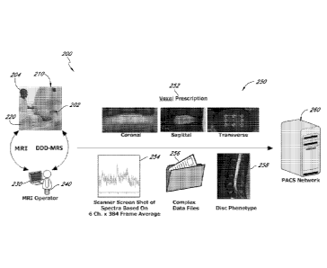
and
improved system approaches, techniques, processors, and methods for conducting
in vivo
clinical magnetic resonance spectroscopy (MRS) on human intervertebral discs,
in particular
according to a highly beneficial mode of this disclosure for using acquired
MRS information
to diagnose painful and/or non-painful discs associated with chronic, severe
axial lumbar (or
"low") back pain associated with degenerated disc disease (or "DDD pain"). For
purpose of
helpful clarity in this disclosure, the current aspects, modes, embodiments,
variations, and
features disclosed with particular benefits for this purposed are generally
assigned the label
"DDD-MRS." However, other descriptors may be used interchangeably as would be
apparent
to one of ordinary skill in context of the overall disclosure. It is also
further contemplated
within the scope of this present disclosure that, while this disclosure is
considered to provide
particular benefit for use involving such human intervertebral discs (and
related medical
indications and purposes), the novel approaches herein described are also
considered more
broadly and applicable to other regions of interest and tissues within the
body of a subject,
and various medical indications and purposes. For purpose of illustration,
such other regions
and purposes may include, without limitation: brain, breast, heart, prostate,
GI tract, tumors,
degeneration and/or pain, inflammation, neurologic disorders, alzheimers, etc.
100891 Various aspects of this disclosure relate to highly beneficial
advances in
each of three aspects, and their various combinations, useful in particular
for conducting a
DDD-MRS exam: (1) MRS pulse sequence for generating and acquiring robust MRS
spectra;
(2) signal processor configured to improve signal-to-noise ratio (SNR) of the
acquired MRS
spectra; and (3) diagnostic processor configured to use information from the
acquired and
processed MRS spectra for diagnosing painful and/or non-painful discs on which
the MRS
exam is conducted in a DDD pain patient.
-15-
CA 02814481 2013-04-11
WO 2011/047197
PCT/US2010/052737
[0090] Several configurations and techniques related to the DDD-MRS
pulse
sequence and signal processor have been created, developed, and evaluated for
conducting
3T (or other suitable field strength) MRS on human intervertebral discs for
diagnosing DDD
pain. A novel "DDD" MRS pulse sequence was developed and evaluated for this
purpose,
and with certain parameters specifically configured to allow robust
application of the signal
processor for optimal processed final signals in a cooperative relationship
between the pulse
sequence and post-signal processing conducted. These approaches can be used,
for example,
with a 3 Tesla (3T) "Signa" MR system commercially available from General
Electric (GE).
Highly beneficial results have been observed using the current disclosed
application
technologies on this particular MR platfoini, as has been demonstrated for
illustration
according to Examples provided herein, and it is to be appreciated that
applying the present
aspects of this present disclosure in combination with this one system alone
is considered to
propose significant benefit to pain management in patients requiring
diagnosis. Accordingly,
various aspects of the present disclosure are described by way of specific
reference to
configurations and/or modes of operation adapted for compatible use with this
specific MR
system, and related interfacing components such as spine detector coils, in
order to provide a
thorough understanding of the disclosure. It is to be appreciated, however,
that this is done
for purpose of providing useful examples, and though significant benefits are
contemplated
per such specific example applications to that system, this is not intended to
be necessarily so
limited and with broader scope contemplated. The current disclosure
contemplates these
aspects broadly applicable according to one of ordinary skill to a variety of
MR platforms
commercially available that may be different suitable field strengths or that
may be
developed by various different manufacturers, and as may be suitably adapted
or modified to
become compatible for use with such different systems by one of ordinary skill
(with
sufficient access to operating controls of such system to achieve this).
Various novel and
beneficial aspects of this present disclosure are thus described herein, as
provided in certain
regards under the Examples also herein disclosed.
[0091] A DDD-MRS sequence exam is conducted according to one example
overview description as follows. A single three dimensional "voxel," typically
a rectangular
= volume, is prescribed by an operator at a control consul, using 3 imaging
planes (mid-
sagittal, coronal, axial) to define the "region of interest" (ROI) in the
patient's body, such as
-16-
CA 02814481 2013-04-11
WO 2011/047197 PCT/US2010/052737
shown in FIGS. 1A-C, for MR excitation by the magnet and data acquisition by
the
acquisition channel/coils designated for the lumbar spine exam within the
spine detector coil
assembly. The DDD-MRS pulse sequence applies a pulsing magnetic and
radiofrequency to
the ROI, which causes single proton combinations in various chemicals within
the ROI to
resonate at different "signature resonant frequencies" across a range. The
amplitudes of
frequencies at various locations along this range are plotted along a curve as
the MRS
"spectrum" for the ROI. This is done iteratively across multiple acquisitions
for a given
ROI, typically representing over 50 acquisitions, often 100 or more
acquisitions, and often
between about 200 and about 600 acquisitions, such as between 300 and 400
acquisitions for
a given exam of a ROI. One acquisition spectrum among these iterations is
called a "frame"
for purpose of this disclosure, though other terms may be used as would be
apparent to one of
ordinary skill. These multiple acquisitions are conducted in order to average
their respective
acquired spectra/frames to reduce the amplitudes of acquired signal components
representing
noise (typically more random or "incoherent" and thus reduced by averaging)
while better
maintaining the amplitudes of signal components representing target resonant
chemical
frequencies of diagnostic interest in the ROI (typically repeatable and more
"coherent" and
thus not reduced by averaging). By reducing noise while maintaining true
target signal, or at
least resulting in less relative signal reduction, this multiple serial frame
averaging process is
thus conducted for the primary objective to increase SNR. These acquisitions
are also
conducted at various acquisition channels selected at the detector coils, such
as for example 6
channels corresponding with the lumbar spine area of the coil assembly used in
the Examples
(where for example 2 coils may be combined for each channel).
[0092] The 3T MRI Signa system ("Signa" or "3T Signa"), in standard
operation
conducting one beneficial mode of DDD-MRS sequence evaluated (e.g. Examples
provided
herein), is believed to be configured to average all acquired frames across
all acquisition
channels to produce a single averaged MRS curve for the ROI. This unmodified
approach
has been observed, including according to the various Figures and Examples
provided herein,
to provide a relatively low signal/noise ratio, with low confidence in many
results regarding
data extraction at spectral regions of diagnostic interest, such as for
example and in particular
regions associated with proteoglycan or "PG" (n-acetyl) and lactate or lactic
acid (LA).
Sources of potential error and noise inherent in this imbedded signal
acquisition and
-17-
CA 02814481 2013-04-11
WO 2011/047197 PCT/US2010/052737
processing configuration of the typical MR system, for example were observed
in conducting
the DDD-MRS pulse sequence such as according to the Examples. These various
sources of
potential error or signal-to-noise ratio (SNR) compromise were determined to
be mostly
correctable - either by altering certain structures or protocols of coil,
sequence, or data
acquisition, or in post-processing of otherwise standard protocols and
structures used.
Among these approaches, various post-acquisition signal processing approaches
were
developed and observed to produce significantly improved and highly favorable
results using
otherwise un-modified operation pre-processing. In particular, various
improvements
developed and applied under the current post-signal processor disclosed herein
have been
observed to significantly improve signal quality and SNR.
[00931 Certain
such improvements advanced under the post-signal processor
configurations disclosed herein include embodiments related to the following:
(1)
acquisition channel selection; (2) phase error correction; (3) frequency error
correction; (4)
frame editing; and (5) apodization. These modules or steps are typically
followed by channel
averaging to produce one resulting "processed" MRS spectrum, when multiple
channels are
retained throughout the processing (though often only one channel may be
retained). These
may also be conducted in various different respective orders, though as is
elsewhere further
developed frame editing will typically precede frequency error correction. For
illustration,
one particular order of these operations employed for producing the results
illustrated in the
Examples disclosed herein are provided as follows: (1) acquisition channel
selection; (2)
phase correction; (3) apodization; (4) frame editing; (5) frequency
correction; and (6)
averaging.
[0094] While
any one of these signal processing operations is considered highly
beneficial, their combination has been observed to provide significantly
advantageous results,
and various sub-combinations between them may also be made for beneficial use
and are also
contemplated. Various illustrative examples are elsewhere provided herein to
illustrate
sources of error or "noise" observed, and corrections employed to improve
signal quality.
Strong signals typically associated with normal healthy discs were evaluated
first to assess
the signal processing approach. Signals from the Signa that were considered
more
"challenged" for robust data processing and diagnostic use were evaluated for
further
-18-
CA 02814481 2013-04-11
WO 2011/047197 PCT/US2010/052737
development to evaluate if more robust metabolite signal can be elicited from
otherwise
originally poor SNR signals from the Signa.
[0095] Additional description further developing these aspects according
to
additional embodiments, and other aspects, is provided below.
[0096] Spine Detector Coil and Patient Positioning
[0097] A typical DDD-MRS exam according to the present embodiments will
be
conducted in an MR scanner in which the patient lies still in a supine
position with a spine
detector coil underneath the patient's back and including the lower spine.
While this scanner
applies the magnetic and RF fields to the subject, the spine detector coil
functions as an
antenna to acquire signals from resonating molecules in the body. The primary
source of
MRS signals obtained from a Signa 3T MR scanner, according to the physical
embodiments
developed and evaluated in the Examples herein this disclosure, are from the
GE HD CTL
456 Spine Coil. This is a "receive-only" coil with sixteen coils configured
into eight
channels. Each channel contains a loop and saddle coil, and the channels are
paired into
sections. For lumbar (and thoracic) spine coverage, such as associated with
lumbar DDD
pain diagnosis, sections 4, 5, and 6 are typically deployed to provide six
individual channel
signals, as shown for example in FIG. 2.
[0098] Defining the Voxel (Voxel Prescription)
[0099] Certain embodiments of this disclosure relates principally to
"single
voxel" MRS, where a single three dimensional region of interest (ROT) is
defined as a
"voxel" (VOlumetric piXEL) for MRS excitation and data acquisition. The
spectroscopic
voxel is selected based on T2-weighted high-resolution spine images acquired
in the sagittal,
coronal, and axial planes, as shown for example in FIGS. 1A-C. The patient is
placed into
the scanner in a supine position, head first. The axial spine images acquired
are often in a
plane oriented with disc angle (e.g. may be oblique) in order to better
encompass the disc of
interest. This voxel is prescribed within a disc nucleus for purpose of using
acquired MRS
spectral data to diagnose DDD pain, according to the present preferred
embodiments. In
general for DDD-MRS applications evaluating disc nucleus chemical
constituents, the
objective for voxel prescription is to capture as much of the nuclear volume
as possible (e.g.
maximizing magnitude of relevant chemical signals acquired), while restricting
the voxel
borders from capturing therewithin structures of the outer annulus or
bordering vertebral
-19-
CA 02814481 2013-04-11
WO 2011/047197 PCT/US2010/052737
body end-plates (the latter being a more significant consideration, where
lipid contribution
may be captured and may shroud chemical spectral regions of interest such as
lactate or
alanine, as further developed elsewhere herein). In fact, the actual operation
may not exactly
coincide with acquiring signal from only within the voxel, and may include
some bordering
region contribution. Thus some degree of spacing between the borders and these
structures is
often desired. These typical objectives may be more difficult to achieve for
some disc
anatomies than others, e.g. relatively obliquely angled discs. For example, L5-
S1 may be
particularly challenging because in some patients it can frequently be highly
angulated,
irregularly shaped, and collapsed as to disc height.
[01001 In certain voxel prescriptions, the thickness is limited by the
scanner's
ability to generate the magnetic gradient that defines the Z-axis (axial
plane) dimension. For
example, a minimum thickness limit is pre-set to 4mm on the GE Signa 3T. While
such pre-
set limits of interfacing, cooperative equipment and related software may
result in limits on
the current application's ability to function in that environment outside of
these limits, the
broad aspects of the current disclosure should not be considered necessarily
so limited in all
cases, and functionality may flourish within other operating ranges perhaps
than those
specifically indicated as examples herein, such as in cases where such other
imparted
limitations may be released.
[01011 These usual objectives and potential limitations in mind, typical
voxel
dimensions and volumes (Z-axis, X-axis, Y-axis, Vol) may be for example 5mm
(thick) by
14mm (width) by 16mm (length), and 1.12cc, though one may vary any or all of
these
dimensions by operator prescription to suit a particular anatomy or intended
application. The
Z-axis dimension is typically limited maximally by disc height (in order to
exclude the end-
plates, described further herein), and minimally by either the set minimum
limitations of the
particular MR scanner and/or per SAR safety considerations, in many disc
applications (such
as specific indication for pain diagnosis or other assessment of disc
chemistry described
herein). This Z-axis dimension will typically be about 3mm to about 6 mm
(thick), more
typically between about 4mm to about 6mm, and most typically will be suitable
(and may be
required to be, per anatomy) between about 4mm to about 5mm. The other
dimensions are
typically larger across the disc's plane, and may be for example between about
15mm to
about 20mm (width and/or length), as have been observed suitable ranges for
most observed
-20-
CA 02814481 2013-04-11
WO 2011/047197 PCT/US2010/052737
cases (e.g. per the Examples herein). While the higher dimension of these
ranges is typically
limited only by bordering tissues desirable to exclude, the opportunity for
patient motion to
alter the relative location of the target voxel relative to actual anatomy may
dictate some
degree of "spacing" from such bordering structures to ensure exclusion. The
smaller
dimensions of the ranges are more related to degraded signal quality that
comes with
excessively small voxel volume, whereas signal amplitude will typically be
directly related to
voxel dimension and volume. Accordingly, voxels within discs will generally
provide robust
results, at least with respect to signal quality, at volumes of at least about
.5cc, and in many
cases at least about .75cc or 1 cc. This typically will be limited by
bordering anatomy to up to
about 2ccs, or in some less typical cases up to about 3ccs for exceptionally
large discs.
These voxel volume ranges will typically be achieved with various combinations
of the
typical axis dimensions as also stated above.
[0102] Also according to the typical voxel prescription objectives and
limitations
stated above, an initial prescription may not be appropriate for achieving
acceptable results,
though this may not be known until a sequence is begun to allow observation of
acquired
signal quality. Accordingly, further aspects of the present disclosure
contemplate a voxel
prescription protocol which prescribes a first prescription, monitors results
(either during
scan or after completion, or via a "pre-scan" routine for this purpose), and
if a lipid signature
or other suspected signal degradation from expected results is observed, re-
prescribe the
voxel to avoid suspected source of contaminant (e.g. make the voxel smaller or
adjust its
dimensions, tilt, or location) and re-run an additional DDD-MRS acquisition
series (retaining
the signal considered more robust and with least suspected signal degradation
suspected to be
voxel error). According to still a further mode, a pre-set protocol for re-
prescribing in such
circumstances may define when to accept the result vs. continue re-trying. In
one
embodiment, the voxel may be re-prescribed and acquisition series re-run once,
or perhaps
twice, and then the best result is to be accepted. It is to be appreciated, as
with many
technology platforms, that operator training and techniques in performing such
user-
dependent operations may be relevant to results, and optimal (or conversely
sub-optimal)
results may track skill levels and techniques used.
[0103] To further illustrate this current aspect of the present
disclosure, the
example of a single voxel prescription according to the typical three planar
slice images is
-21-
CA 02814481 2013-04-11
WO 2011/047197
PCT/US2010/052737
shown in Figures 1A-1C as follows. More specifically, Fig. 1 A shows a coronal
view
oriented aspect of the voxel prescription. Fig. 1B shows a sagittal view
oriented aspect of the
voxel prescription. Fig. 1C shows an axial view oriented aspect of the voxel
prescription.
[0104] The "DDD" MRS Pulse Sequence - PRESS
[01051 The DDD-MRS pulse sequence according to one embodiment shares
certain similarities, though with certain differences and modifications
defined herein, with
another MRS pulse sequence called "PROSE". PROSE is primarily intended for use
for
diagnosing prostate cancer, and is approved for use and sale and available
from GE on 1.5T
GE MR systems. The DDD-MRS pulse sequence of the present embodiments, and
PROSE
for further reference, employ a sequence approach called Point RESolved
Spectroscopy
(PRESS). This involves a double spin echo sequence that uses a 900 excitation
pulse with
two 180 slice selective refocusing radio frequency (RF) pulses, combined with
3D chemical
shift imaging (CSI) phase encoding gradients to generate 3-D arrays of
spectral data or
chemical shift images. Due to the small size, irregular shape, and the high
magnetic
susceptibility present when doing disc spectroscopy for DDD pain, the 3D phase
encoding
option available under PROSE is not an approach typically to be utilized under
the current
disclosed version of DDD-MRS sequence, and single voxel spectra are acquired
by this
version embodiment of DDD-MRS pulse sequence. This unique relative
configuration for
the DDD-MRS pulse sequence can be accomplished by setting the user control
variables
(CVs) for the matrix acquisition size of each axis to 1 (e.g., in the event
the option for other
setting is made available). Further aspects of pulse sequence approaches
contemplated are
disclosed elsewhere herein. It is to be appreciated that while the modified
PRESS approach
herein described is particularly beneficial, other approaches may be taken for
the pulse
sequence according to one of ordinary skill consistent with other aspects and
objectives
herein described and without departing from the broad aspects of intended
scope herein.
[0106] Water and Lipid Signal Suppression - CHESS
[0107] In another sequence called "PROBE" also commercially available
from
GE, and which is a CSI sequence used for brain spectroscopy, the lipid/fat
signals are
believed to be resolved through the use of long TE (144ms) periods and 2
dimensional
transformations (2DJ). These acquisition and signal processing techniques are
believed to be
facilitated by the large voxel volumes prescribed in the brain as well as the
homogeneity of
-22-
CA 02814481 2013-04-11
WO 2011/047197
PCT/US2010/052737
the brain tissue resulting in relatively narrow spectral line widths. In the
prostate region
targeted by the different pulse sequence of PROSE, however, the voxel
prescriptions are
much smaller and it is often impossible to place the voxel so as to assuredly
exclude tissues
that contain lipid/fat. Therefore, two water and lipid suppression approaches
are available
and may be used, if warranted, in the PROSE sequence: "BASING" and "SSRF"
(Spectral
Spatial Radio Frequency). An even more challenging environment of bordering
lipid and
reduced homogeneity has been observed with the current DDD pain application of
the
lumbar intervertebral discs where the current ROT within disc nuclei are
closely bordered by
vertebral bodies with bone marrow rich in lipid content. However, due both to
the desire to
use short TE times (e.g. 28ms) for the current DDD pain application in lumbar
spine, and the
desire to observe MRS signatures of other chemicals within disc nuclei that
may overlap with
lipid signal contribution along the relevant DDD-MRS spectrum, these
water/lipid
suppression approaches as developed for brain and prostate application are not
necessarily
optimized for DDD-MRS application in many circumstances. While a SSRF
suppression
approach for lipid resonances may be employed in the DDD-MRS sequence, the
narrow band
RF pulse required for this may require a long RF period and amplitude that
will exceed the
SAR level for many MR systems.
[0108] Water suppression is also provided by a CHESS sequence
interleaved or
otherwise combined in some manner with the PRESS sequence in order to provide
appropriate results. Optimization of the residual water spectral line for
frequency correction
is done, according to one highly beneficial further aspect of the present
disclosure, with the
setting prescribed for the third flip angle. The angle is lowered to reduce
the water
suppression function which increases the residual water spectral line
amplitude. Conversely
higher relative third flip angles will increase water suppression for reduced
water signal in an
acquired MRS spectrum. A particular flip angle for this purpose may be for
example about
125, though may be according to other examples between about 45 degrees and
about 125
degrees (or as much as about 145 degrees). Accordingly, in one aspect, the
flip angle may be
for example at least about 45 degrees. In another aspect, the flip angle may
be up to 125
degrees or even up to 145 degrees. Notwithstanding these examples, an expanded
experimental data set of 79 discs in 42 subjects represented under Example 3
included robust,
reliable results across this population with an average flip angle of about
120 or 121 degrees
-23-
CA 02814481 2013-04-11
WO 2011/047197 PCT/US2010/052737
+/- about 33 degrees. Moreover, a later component of that population conducted
with further
refinements revealed a majority of cases suitable at a flip angle between
about 65 degrees
and about 125 degrees, and in fact with most found to be sufficient at about
85 degrees. It is
to be appreciated that despite these specific number and range examples, and
robust results
observed therefrom, it is also believed that flip angles within about 5 or 10
degrees apart are
likely to produce susbstantially similar results for purposes intended herein.
[0109] This flip angle aspect of the present disclosure is another
example where
some degree of customization may be required, in order to optimize water
signal for a given
disc, in a given particular MR system. As some discs may be more dehydrated or
conversely
more hydrated than others, the water suppression may be more appropriate at
one level for
one disc, and at another level for another disc. This may require some
iterative setting and
acquisition protocol to optimize, whereas the angle example described herein
is considered
appropriate for most circumstances and may be a pre-defined starting place for
"first try."
[0110] For further clarity and understanding of the present DDD-MRS
pulse
sequence embodiments introduced above and also elsewhere herein described,
FIG. 3A
shows an example of a CHESS water suppression pulse sequence diagram, whereas
FIG. 3B
shows an example of a combined CHESS - PRESS pulse sequence diagram.
[0111] Very Selective Saturation (VSS) Bands
[0112] The volume excitation achieved using PRESS takes advantage of
three
orthogonal slices in the form of a double spin echo to select a specific
region of interest. In
some embodiments, the range of chemical shift frequencies (over 400 Hz for
proton at 3.0T)
is not insignificant relative to the limited band width of most excitation
pulses (1000-2000
Hz). The result can be a misregistration of the volume of interest for
chemical shift
frequencies not at the transmitter frequency. Thus, when a PRESS volume is
resolved by
MRS, the chemical levels may be not only dependent on tissue level, T1 and T2,
but also
dependent on location within the volume of interest. In some embodiments, due
to
imperfections in the RF pulse, out of volume excitation may occur which can
present signals
from chemicals that are not in the frequency/location range of interest.
[0113] Accordingly, another feature that is contemplated according to a
further
mode of the DDD-MRS sequence is the use of very selective saturation (VSS)
pulses. This
is often beneficial to deploy for example for removal of signal contamination
that may arise
-24-
CA 02814481 2013-04-11
WO 2011/047197 PCT/ES2010/052737
from chemical shift error due to the presence of lipids within the voxel as
well as outside the
selected ROT or voxel in the disc nuclei. In the default operating mode of one
DDD-MRS
sequence approach, in some regards sharing some similarities with PROSE, for
example,
multiple pairs of VSS RF suppression bands are placed symmetrically around the
prescribed
DDD-MRS voxel. In certain embodiments, the voxel in this approach is
oversized, such as
for example by 120% (e.g. PRESS correction factor = about 1.2). The DDD-MRS
sequence
according to this mode uses the VSS bands to define the actual DDD-MRS volume.
It is
believed that up to about six additional VSS bands may be prescribed (each
consisting of
three VSS RF pulses) graphically in PROSE, with the goal of reducing the
chemical shift
error that can occur within the voxel as well as suppress excitation of out of
voxel tissue
during the PRESS localization of the voxel. According to some observations in
applying
DDD-MRS to disc spectroscopy, these additional graphic VSS pulses were found
to not
significantly improve the volume selection. In other observations, some
benefit is suspected
to have resulted. Accordingly, while they may provide benefit in certain
circumstances, they
also may not be necessary or even desired to be used in others.
[0114] FIG. 3C shows a schematic diagram of certain aspects of a
combined
CHESS ¨ VSS- PRESS pulse sequence diagram also consistent with certain aspects
of the
present disclosure. As also shown for further illustration in multiple
respective image planes
in FIGS. 4A-B, multiple VSS bands are placed around the voxel prescription in
each plane to
reduce out of voxel excitation and chemical shift error present during the
PRESS localization
of the voxel.
[0115] PRESS timing parameters
[0116] For purpose of comparative reference, the echo time (TE) of about
130 ms
is believed to be the default selection typically used for PROSE data
acquisitions. This echo
time is typically considered too long for DDD-MRS pulse sequence applications
for
acquiring robust disc spectra due to the small voxel volume and shorter T2
relaxation times of
the chemical constituents of lumbar intervertebral discs, leading to a
dramatic decrease in
signal to noise in long echo PRESS spectra. Therefore a shorter echo time
setting for the
scanner, such as for example about 28 milliseconds, is generally considered
more appropriate
and beneficial for use in the current DDD-MRS sequence and DDD pain
application (though
this may be varied as would be apparent to one of ordinary skill based upon
review of this
-25-
CA 02814481 2013-04-11
WO 2011/047197 PCT/US2010/052737
total disclosure and to suit a particular situation). A frame repetition time
(TR) of for
example about 1000 ms provides sufficient relaxation of the magnetic dipoles
in the ROT and
leads to reasonable acquisition times and is believed to represent a
beneficial compromise
between short acquisition times and signal saturation at shorter values of TR
(though this
may also be varied, as also elsewhere herein described). Other appropriately
applicable
operating parameter settings for PRESS spectra suitably applicable to the DDD-
MRS
sequence may be, for example: number of data points equal to about 1024,
number of
repetitions equal to about 300, and example typical voxel size of about 4mm x
18mm x
16mm (1.12cc). Furthermore, first, second, and third flip angles of PRESS for
the current
DDD-MRS sequence embodiment may be for example 90, 167, and 167, respectively
(though these may slightly vary, and user-defined settings may not always
reflect actual
angle ¨ for example the latter two values may be exchanged with or represent
one example of
an actual result of a 180 degree setting).
[0117] Summary of User Control Variable (CV) Examples for DDD-MRS
Sequence
[0118] The foregoing disclosure describes various user controllable
sequence
settings observed to be appropriate and of particular benefit for use in an
example DDD-
MRS sequence according to the current disclosure and for use for diagnosing
DDD pain, as
contemplated under the preferred embodiments herein. These are further
summarized in
Table 1 appended herewith at the end of this disclosure.
[0119] One or more of these CVs may comprise modifications from similar
settings that may be provided for another CHESS-PRESS or CHESS-VSS-PRESS pulse
sequence, such as for example PROSE, either as defaults or as user defined
settings for a
particular other application than as featured in the various aspects herein
this disclosure.
These CV settings, in context of use as modifications generally to a sequence
otherwise
sharing significant similarities to PROSE, are believed to result in a highly
beneficial
resulting DDD-MRS sequence for the intended purpose of later signal
processing, according
to the DDD-MRS signal processor embodiments herein described, and performing a
diagnosis of DDD pain in discs examined (the latter according for example to
the DDD-MRS
diagnostic processor aspects and embodiments also herein disclosed). However,
it is also
appreciated that these specific settings may be modified by one of ordinary
skill and still
-26-
CA 02814481 2013-04-11
WO 2011/047197
PCT/US2010/052737
provide highly beneficial results, and are also contemplated within the broad
intended scope
of the various aspects of this present disclosure.
[0120] Data Acquisition of DDD-MRS Pulse Sequence
[0121] The signal detected in the MR spectrometer in the receiving
"detector"
coil assembly, after exposing a sample to a radio frequency pulse, is called
the Free
Induction Decay (FID) for purpose of this disclosure. In modem MR
spectrometers the MR
signal is typically detected using quadrature detection. As a result, the
acquired MR signal is
composed of two parts, often referred as real and imaginary parts of the FID.
A schematic
example of the time domain FID waveform is shown in FIG. 5, which shows the
real (Sx)
and imaginary (Sy) parts of an FID (right) that correspond to x and y
components of the
rotating magnetic moment M (left).
[0122] FIDs are generated at the period defined by TR. Thus a TR of
about 1000
milliseconds, according to the example embodiment described above, equals a
rate of about 1
Hz (about one FID per second). The FID signal received from each coil channel
is digitized
by the scanner to generate a 1024 point complex number data set or acquisition
frame. An
MRS scan session consists of a number of frames of unsuppressed water FIDs
(such as for
example may be about 16 frames) and up to 368 or more (as may be defined by an
operator
or setting in the pulse sequence) frames of suppressed water FIDs, which
together are
considered an acquisition series. The unsuppressed water FIDs provide a strong
water signal
that is used by the signal processing to determine which coils to use in the
signal processing
scheme as well as the phase information from each coil (and in certain
embodiments may
also be used for frequency error correction). However, due to gain and dynamic
range in the
system these high water content unsuppressed frames do not typically provide
appropriate
resolution in the target biomarker regions of the associated spectra to use
them for diagnostic
data purposes. The suppressed water FIDs are processed by the DDD-MRS
processor to
obtain this spectral information, although the unsuppressed frames may be used
for certain
processing approaches taken by the processor.
[0123] For further illustration, FIG. 6 shows a plot of all the FIDs
obtained in a
DDD-MRS pulse sequence scan according to certain present illustrative
embodiments, and is
an amplitude plot of complex data from a standard DDD-MRS acquisition with the
y-axis
-27-
CA 02814481 2013-04-11
WO 2011/047197
PCT/US2010/052737
representing the magnitude of FID data and the x-axis representing serial
frame count over
time.
[0124] DDD-MRS Pulse Sequence Data Transfer from MR System to Post-
Processor
[0125] The MR scanner generates the FIDs using the defined sequences to
energize the volume of interest (VOI), digitizes them according to the defined
data
acquisition parameters, and stores the data, typically as floating point
numbers. While this
data may be packaged, e.g. in "archive file," and communicated in various
formats and
methods, one example is provided here. A data descriptor header file (DDF)
with all the
aforementioned parameters along with voxel prescription data is appended to
the data to
generate the archive file. Examples of certain parameters provided in a DDF,
are as
follows:studyID (String); seriesNum (Integer for assigned Series Number);
studyDate(String
date code); seriesDesc (String for series description); rootName (String);
nSamps (Integer for
number of complex samples, typically 1024); nFrames (Integer for number of
frames or
reps); coilName (String); pulseSeqName (String); Te (Float, echo time, in ms);
Tr (Float,
repetition time, in ms); TxFreq (Float, in MHz); nSatBands (Integer, number of
saturation
bands); voxTilt (Float, voxel tilt about x-axis, in degrees); voxVol (Float,
Voxel volume in
cc); voxX (Float, Voxel X dimension, in mm); voxY (Float, Voxel Y dimension,
in mm);
voxZ (Float, Voxel Z dimension, in mm). The archive file can include data
received from
the MR scanner that is representative of the anatomy of a patient (e.g.,
representative of the
chemical makeup of tissue inside the area of interest inside an intervertebral
disc of the
patient's spine).
[0126] The archive file may then be transferred to another computer
running an
application written in a language, such as for example Matlab R2009a (e.g.
with "Image
Processing Toolbox" option, such as to generate time-intensity plots such as
shown in
various Figures herein), which opens the archive file. The Matlab application
may be user-
configurable, or may be configured as full or partial executables, and is
configured to signal
process the acquired and transferred DDD-MRS information contained in the
archive file,
such as according to the various signal processing embodiments herein. Other
software
packages, such as "C," "C+," or "C++" may be suitably employed for similar
purposes. This
application, subsequently referred to as the DDD-MRS signal processor, parses
information
-28-
CA 02814481 2013-04-11
WO 2011/047197
PCT/US2010/052737
pertinent to the signal processing of the data from the data description
header, and imports
the FID data acquired at each detector coil for subsequent signal processing.
It will be
understood that the DDD-MRS signal processor can be implemented in a variety
of manners,
such as using computer hardware, firmware, or software, or some combination
thereof In
some embodiments, the DDD-MRS signal processor can comprise a computer
processor
configured to execute a software application as computer-executable code
stored in a non-
transitory computer-readable medium. In some embodiments, the computer
processor can be
part of a general purpose computer. In some embodiments, the DDD-MRS signal
processor
can be implemented using specialized computer hardware such as integrated
circuits instead
of computer software. It will be understood that the DDD-MRS signal processor,
as well as
other components described herein that may be implemented by a computer, can
be
implemented by multiple computers connected, for example, by a network or the
internet.
Thus, algorithms, processes, sequences, calculations, and tasks, etc.
described herein can be
divided into portions to be performed by multiple computer processors or other
hardware
located on multiple physically distinct computers. Also, some tasks that are
described herein
as being performed by distinct computers or systems may be performed by a
single computer
or a single integrated system.
[0127] The archive file and related MRS data may be communicated via a
number of available networks or methods to external source for receipt,
processing, or other
form of use. In one particular typical format and method, the information is
communicated
via picture archiving and communication system (PACS) that has become
ubiquitous for
storing and communicating radiologic imaging information. In addition to the
archive file
with DDF and stored MRS data, accompanying MRI images may also be stored and
communicated therewith, e.g. in standardized "digital imaging and
communications in
medicine" or "DICOM" format.
[0128] The data transfer described may be to a local computer processor
for
processing, or more remotely such as via the web (typically in secure format).
In alternative
to data transfer of acquired MRS data pre-processing to an external system for
post-
processing as described above, e.g. MRS signal processor and diagnostic
processor aspects of
this disclosure, all or a portion of the various aspects of the present
embodiments may be
installed or otherwise integrated within the MR system itself, e.g. a computer
based
-29-
CA 02814481 2013-04-11
WO 2011/047197 PCT/US2010/052737
controller or processor embedded therewithin or otherwise connected thereto,
for operation
prior to packaging results for output (and any remaining portions might be
performed
peripherally or more remotely).
[0129] DDD-MRS Signal Processing
[0130] Upon the acquisition of all MRS data from a DDD-MRS pulse
sequence
exam, according to certain aspects of the present embodiments, the MR scanner
system will
typically provide the operator with a spectral image that is the averaged
combination of all
frames across all the 6 detection channels (coils). An example of such a
waveform from an
MRS pulse sequence exam acquired for an ROI in a disc nucleus via a GE Signa
3T MR
system is shown in FIG. 7, which shows a typical scanner-processed spectral
signal plot of
combined, averaged channels. FIG. 8 shows the magnitude only (no correction)
MRS
spectral images of each of the six channels which are aggregated to form the
output from the
example MR system as shown in FIG. 7, and thus this raw uncorrected individual
channel
spectral data output provides the input to the DDD-MRS signal processor of the
present
embodiments.
[0131] According to one highly beneficial mode, the DDD-MRS signal processor
is
configured to conduct a series of operations in temporal fashion as described
herein, and as
shown according to the present detailed embodiments in the flow charts
illustrated in general
to increasing detail for the various component modes and operable steps in
FIGS. 9A-C.
More specifically, FIG. 9A shows a general schematic overview for the flow of
a diagnostic
system 2 that includes a signal processor 4 and a diagnostic processor 6.
Signal processor
includes various sub-components and processors that carry out certain steps,
such as a
channel selector that conducts channel or "coil" selection step 10, phase
corrector that does
phase correction step 20, apodizer that conducts apodizer step 30, domain
transformer that
conducts the domain transform step 44 such as from time domain to frequency
domain,
frame editor that conducts frame editing steps 50, frequency corrector that
conducts
frequency correction steps 60, and channel combiner that conducts combining or
averaging
steps 70 to aggregate retained channels into one final post-processed spectral
results (not
shown). Following signal processing steps 6, a diagnostic processor conducts
diagnostic
processing of the signal processed signals through data extraction steps 110,
diagnostic
algorithm application steps 120, and patient or diagnostic report generation
130. While this
-30-
CA 02814481 2013-04-11
WO 2011/047197 PCT/US2010/052737
configuration is considered highly beneficial, these same or similar tasks may
be performed
in different order, as would be apparent to one of ordinary skill.
[0132] For illustration, FIGS 9B-C show further details regarding some of
these
specific steps, and also illustrate a different order than has been shown and
referenced to
FIG. 9A. More specifically, the signal processor 4 in shown to include the
main primary
steps shown in FIG. 9A, but in finer detail and different order. It some
embodiments, the
steps shown in FIGS. 9A-C may be performed in an order different than those
shown in
FIGS. 9A-C. Also, in some embodiments, steps that are shown in FIGS. 9A-C can
be
omitted, combined with other steps, or divided into additional sub-steps.
Additionally, in
some cases, additional steps not specifically shown in FIGS. 9A-C can be
performed in
addition to the steps shown in FIGS. 9A-C.
[0133] Channel selection includes the following steps: signal power
measurement
step 11 measures signal power for SNR calculation, as shown here in the
specific
embodiment in first 100 points of FID with unsuppressed water. Noise power
measurement
step 13 measures noise in the last 100 points, for example, of the FID with
unsuppressed
frames. SNR estimate 15 is then conducted, at which point thereafter channel
selection step
17 is conducted per the channel with the maximum or highest signal. Channel
selection
includes an additional step 18 where additional channels are selected if
within range of the
strongest, e.g. about 3dB. Upon completing channel selection, an index of
selected channels
is generated (step 19).
[0134] Frame editing operation 50 is also shown, with transformation of
unsuppressed water frame to frequency domain 51, locate water peak in +1- 40Hz
per peak
location step 53, frame confidence level calculation 55, frame frequency error
and store 57,
and actual frame selection step 59 based upon minimum confidence level
threshold (e.g. .8)
Phase correction 20 is also done per applying 21 1st order linear curve fit to
the FID of each
unsuppressed water frame (e.g. n=16)., obtaining average of zero order terms
from the curve
fit 23, and rotate 25 all suppressed water frame FIDs by zero order term.
Apodization 30
includes for each selected channel and each frame indexed for frequency
correction 31, then
apply 250 point boxcar function to the FID (step 33). In addition, frequency
correction 60
entails for each selected channel and each frame indexed for frequency
correction and
apodization 61, transform 63 the frame (FID) to the frequency of domain, and
locate the
-31-
CA 02814481 2013-04-11
WO 2011/047197 PCT/US2010/052737
frequency error 65 for the frame as identified during frame editing. The
spectrum is shifted
67 by the frequency error value to frequency correct the spectrum. Step 69
adds frequency
corrected spectrum to many to spectral average for all selected channels.
[0135] As also shown in FIG. 9C for the diagnostic processor 6, data
extraction 110
involves opening 111 the acquisition spectral average lot generated in
frequency correction,
scan step 113 of spectral plot for metabolite features and apply to bins, and
record data bins
to acquisition metabolite 115. The diagnostic algorithm 120 itself involves
opening the
acquisition metabolite file extracted from spectral average 121, extract 123
metabolite
features required by diagnostic linear regression equations, and generate 125
acquisition
diagnostic score and store to file. Report generation 130 includes open
acquisition diagnostic
score fill 131, open DICOM file 133 for Patient ID associated with acquisition
diagnostic
score, extract 135 sagittal image from the DICOM report, apply 137 acquisition
score to
sagittal image for each scanned disc, and return sagittal image to DICOM
report 139.
[0136] According to the current example embodiment, a first operation of the
DDD-
MRS processor assesses the SNR of each channel. This is done to determine
which channels
have acquired sufficiently robust signal to use for data processing and
averaging. The result
may produce one single channel that is further processed, or multiple channels
that are later
used in combination under multi-channel averaging. In the majority of acquired
signals
observed according to the Examples disclosed herein, only a subset of the 6
lumbar
acquisition channels were determined to be sufficiently robust for use.
However, the
standard system output averages all 6 channels. Accordingly, this filtering
process alone ¨
removing poor signal channels and working with only stronger signal channels ¨
has been
observed to dramatically improve processed spectra for diagnostic use in some
cases. While
various techniques may be suitable according to one of ordinary skill, and
thus contemplated
herein, according to the present illustrative embodiment the SNR is calculated
by obtaining
the average power in the first 100 data points (the signal) and the last 100
points (the noise)
of the unsuppressed water FID. The unsuppressed water FIDs signals are used
because of the
strong water signal. The channel with the greatest SNR, and channels within a
predetermined
threshold variance of that strongest one, e.g. within about 3 dB for example,
are preserved for
further processing and as candidates for multi-channel averaging ¨ other
channels falling
-32-
CA 02814481 2013-04-11
WO 2011/047197 PCT/US2010/052737
below this range are removed from further processing (though may be used for
further
processing, yet removed from final results).
101371 Further examples and embodiments for evaluating relative channel
quality are
provided as follows. One additional indication of channel quality that may be
observed and
used is the line width of the unsuppressed water signal based on the averaged
frequency and
phase corrected FFTs of the coil channels with the highest SNRs. This is
computed to serve
as a general indicator of signal quality as determined by the quality of the
shimming process
and to provide an estimate of the resolution we should expect in the chemical
shift spectrum.
Another indication of channel quality is the degree of water suppression. This
has utility in
determining the optimum degree of water suppression to apply in the
acquisition protocol.
The water suppression should leave enough residual water signal to use as a
reference to
reliably perform frame-by-frame frequency correction but not so much that
water signal
artifacts affect the chemical shift spectrum in the metabolite areas of
interest. Such artifacts
include simple spectral leakage as well as phase modulation sidebands due to
gradient
vibration induced Bo modulation.
[0138] Further to the present embodiments and per further reference to
FIGS. 9A-
B, a second operation conducted by the DDD-MRS processor is phase alignment,
or phase
error correction. This is performed to support coherent summation of the
signals from the
selected channels and the extraction of the absorption spectra. This is often
necessary, or at
least helpful, because in many cases a systemic phase bias is present in the
different
channels. This systemic phase bias is best estimated by analysis of the data
frames (e.g.
about 16 frames in the DDD-MRS pulse sequence of the current illustrative
detailed
embodiments) collected at the beginning of each scan without water
suppression. This
operation, according to one mode for example, analyzes the phase sequence of
the complex
samples and fits a polynomial to that sequence. A first-order (linear) fit is
used in one further
illustrative embodiment. This is believed to provide a better estimate of the
offset than
simply using the phase of the first sample, as is often done. This is because
eddy current
artifacts, if present, will be most prominent in the first part of the frame.
The offset of the
linear fit is the initial phase. Observation has indicated that the first 150
samples (75 mS at
the typical 2000 samples-per-second rate) typically provide reliable phase
data. The fit is
performed on each of the water-unsuppressed frames for each channel and the
mean phase of
-33-
CA 02814481 2013-04-11
WO 2011/047197 PCT/US2010/052737
these is used to phase adjust the data for the corresponding channel. This is
accomplished by
performing a phase rotation of every complex sample in each frame to
compensate for the
phase offset as estimated above, setting the initial phase to zero.
[0139] The offset of the linear fit is the phase bias with respect to
zero and the
slope is the frequency error with respect to perfect center-tuning on the
water signal. Only the
offset portion of the curve fit is used to phase correct the data. An
illustrative example of this
is shown in schematic form in FIG. 10, which shows phase angle before and
after phase
correction. The phase angle signal is shown as the dotted line. The solid line
is the least
squares fit estimate. The dashed line is the phase and frequency corrected
signal, though the
offset component is used to phase correct and frequency correction is
performed
subsequently in the temporal process according to the present DDD-MRS
processor
embodiment.
[0140] The real-part squared MRS spectral results of phase correction
for each of
all the six channels shown prior to correction in FIG. 8 is shown in FIG. 11,
with channels 1-
3 indicated from left to right at the top, and channels 4-6 indicated from
left to right at the
bottom of the figure. The averaged spectrum of the selected, phase corrected
channels
(channels 1 and 2) is shown in FIG. 12, which reflects significant SNR
improvement versus
the uncorrected all channel average spectrum shown in FIG. 7.
[0141] Frame Editing
[0142] While it is contemplated that in some circumstances individual
MRS
acquisition frames may provide some useful information, frame averaging is
prevalently
indicated in the vast majority of cases to achieve a spectrum with sufficient
SNR and
interpretable signal at regions of interest for pathology assessment. It is,
at most, quite rare
that an individual frame will have sufficient SNR for even rudimentary
metabolite analysis to
the extent providing reliable diagnostic information. Often individual frames
along an
acquisition= series will have such low SNR, or possess such artifacts, that
they make no
improvement to the average - and in fact may even degrade it. To the extent
these "rogue"
frames may be recognized as such, they may be excluded from further processing
¨ with only
robust frames remaining, the result should improve.
[0143] Accordingly, a further mode of the present DDD-MRS processor
embodiment utilizes a frame editor to conduct frame editing to identify those
frames which
-34-
CA 02814481 2013-04-11
WO 2011/047197 PCT/US2010/052737
vary sufficiently from the expected or otherwise observed acquisition results
such that they
should be excluded, as is also represented schematically in the flow diagram
examples of
FIGS. 9A-B. In one aspect of the underlying concern, certain patient motions
during an
acquisition may result in signal drop-out as well as frequency shifts (e.g.
magnetic
susceptibility artifact). While involuntary motion, e.g. respiration, is a
common cause of
frequency shifts, these are typically sufficiently minor and within a range
that they are not
believed to implicate signal quality other than the shift itself (which can be
significant source
of SNR degradation, but correctable per the present disclosure). However,
other more
significant movements (e.g. voluntary) may cause sufficiently significant
shifts to seriously
degrade the acquired spectrum, beyond merely correctable spectral shifts. For
example, such
activity may move the voxelated region to include adjacent tissues versus only
the intended
VOI upon prescription prior to the motion. If the salient artifact is
frequency shift, a
correction may be applied and the frame can be used to make a positive
contribution to the
averaged spectrum. If a frame is discarded its contribution is lost, and
across sufficient
number of discarded frames across a series the result may not include a
sufficient number of
frames in the average for a reliable SNR in the resulting spectrum. The DDD-
MRS
processor, according to the current embodiment, analyzes the residual water
signal in each
frame to determine if it is of sufficient quality to support frequency
correction.
[0144] FIG. 13 shows a time-intensity plot which illustrates a scan
series with
frequency shifts and "drop outs" with SNR changes considered to represent
corrupted frames
due to patient motion. More specifically, this shows 1 dimensional horizontal
lines for each
frame, with signal amplitude reflected in "brightness" or intensity (e.g.
higher values are
whiter, lower are darker), with time across the serial acquisition of the
series progressing top
to bottom vertically in the Figure. A vertical band of brightness is revealed
to the left side of
the plot. However, in this particular example, there is a clear break in this
band as "drop out"
frames. After excluding the "drop out" frames (center of time sequence between
about 75
and 175 MRS frames, it was still possible to obtain a high quality final
averaged spectrum
from this scan using the remaining robust frames, as further developed
immediately below.
[0145] FIGS. 14A and 14B show the confidence level estimate and the
frame by
frame frequency error estimate, respectively, which are used according to the
present
embodiment for frame editing according to this acquisition series example of
FIG. 13. More
-35-
CA 02814481 2013-04-11
WO 2011/047197 PCT/US2010/052737
specifically, FIG. 14A shows the frame by frame confidence level, with
confidence level on
the Y-axis, and the sequential series of frame acquisitions along a scan
indicated along the X-
axis. FIG. 14B shows the actual frequency error along the Y-axis, for the same
frame series
along the X-axis. This is based on analyzing the characteristics of the
residual water peak
and the noise in a band 80 Hz wide (for 3T processing, the band would be 40 Hz
wide at
1.5T) around the center-tuned frequency. The largest peak is assumed to be the
water signal
and the assumption is qualified by the confidence estimate. For the purpose of
this example,
if the confidence value is above a threshold, i.e. 0.8, the frame is flagged
as a candidate for
frequency correction and thus "retained." As seen from the plots in FIGS. 14A-
B, when the
confidence is low, the variance of the frequency error estimate is greatly
increased. The final
qualification step, per this example, is to determine if there are enough
qualified candidate
frames to achieve sufficient SNR improvement when averaged. This threshold
limit for
proceeding with frequency correction (and thus frame editing therefore) has
been empirically
established as 90 frames meeting the criteria. According to the present
embodiments, this
has been observed to provide sufficiently robust results per the Examples
described herein. It
is to be appreciated, however, that other limits may be appropriate in various
circumstances.
The number of frames required will be based upon the SNR levels achievable
from the
completed signal processing. This will be paced by SNR of input signal
acquisitions to begin
with, and performance of other signal processing modes and steps taken with
those signals.
According to the acquisitions under the Examples disclosed herein, SNR is
believed to
increase over about 150 frames, and then with little gained typically
thereafter, though the 90
frame minimum limit has been observed to provide sufficient results when
reached (in rare
circumstances). In the event the result drops below the 90 frame limit, the
DDD-MRS
processor is still configured to proceed with other modes of signal
processing, signal quality
evaluation, and then diagnostic processor may be still employed ¨ just without
the added
benefit of the frame editing and frequency error correction.
[0146] Further description related to acceptable confidence level
estimate
approach according to the present disclosure is provided as follows, for
further illustration of
this embodiment for the frame editing and frequency correction modes of the
disclosure. The
discrete amplitude spectrum can be analyzed in the range of the center-tuned
frequency 40
Hz for example in the case of a 3T system acquisition, and half this bounded
range (e.g. 20
-36-
CA 02814481 2013-04-11
WO 2011/047197
PCT/US2010/052737
Hz) for a 1.5T system acquisition. The highest peak is located to determine
its width at the
half-amplitude point. Next, the total spectral width of all parts of the
spectrum which exceed
the half-amplitude point of the highest peak are determined. The confidence
estimate is
formed by taking the ratio of the spectral width of the greatest peak divided
by the total
spectral width which exceeds the threshold. If there is only a single peak
above the
threshold, the confidence estimate will be 1.0, if there are many other peaks
or spectral
components which could be confused with the greatest one, then the estimate
will approach
0Ø This provides a simple and robust estimate of the randomness or dispersal
of energy in
the vicinity of the water peak. Like another approach using entropy
measurement, e.g. as
described below, this current approach provides at least one desirable
characteristic in that it's
performance is substantially invariant with amplitude.
[0147] Yet another system and method to compute a confidence estimate
that also
can be appropriate is provided as follows. The spectral entropy is computed by
normalizing
the spectrum to take the form of a probability mass function. The Shannon
entropy or
uncertainty function, H, is then computed as follows:
H = -Epi log, pi
where p = probability, and i = frequency index value (e.g. -40 to +40 hz).
[0148] It is to be appreciated that other approaches to quantify
randomness or
uncertainty of the spectrum may also be suitable for use with the various
DDD_MRS signal
processor aspects of the present disclosure.
[0149] For further understanding and clarity re: the ultimate impact
frame editing
as described herein, the unprocessed absorption spectrum plot for all six
channels from the
patient (with the compromised frames included as aggregated in the respective
channel
spectra) in various views in prior Figures is shown for each respective
channel in the six
indicated panes shown in FIG. 15. The phase and frequency corrected spectrum
averaged for
selected channels 3 and 4, and for all 256 acquired frames aggregated/averaged
per channel,
without applying frame editing and thus including the corrupted frames, is
shown in FIG.
16A. In contrast, FIG. 16B shows a similar phase and frequency error corrected
spectrum
averaged for the same selected channels 3 and 4, but for only 143 of the 256
acquired frames
aggregated/averaged per channel (the remaining 113 frames edited out), per
frame editing
applied according to the present embodiments prior to frequency error
correction. The peak
-37-
CA 02814481 2013-04-11
WO 2011/047197
PCT/US2010/052737
value in the combined lactate-alanine (LAAL) region of the frame edited
spectrum of FIG.
16B is significantly increased ¨ with corresponding increase in SNR ¨ relative
to the peak
value in the same LAAL region of the non-frame edited spectrum in FIG. 16A
(e.g. the peak
value increases from about 3.75 x 10⁸ to about 4.4 x 10⁸), a nearly 20% SNR
increase despite
about 40% corresponding reduction in the number of FID frames used.
[0150] While the examples addressed above by reference to FIGS. 13-16B
address a highly beneficial embodiment for frame editing based upon water
signal, other
frame editing embodiments are also contemplated, and many different features
of acquired
DDD-MRS signals may be used for this purpose. One such further embodiment is
shown for
example by reference to another DDD-MRS pulse sequence acquisition for another
disc in
another subject by reference to FIGS. 17A-F. More specifically, per the time-
intensity plot
shown for this acquisition in FIG. 17A, while the water signal region of the
acquired spectral
series (bright vertical band on left side of plot) reveals some shift
artifact, another bright band
appears at a broader region on the right side of the spectra, between about
150 and 200 FID
frames into the exam. This region is associated with lipid, and also overlaps
with lactic acid
(LA) and alanine (AL) regions of diagnostic interest according to the present
detailed
embodiments and Examples. This is further reflected in FIG. 17B which shows a
waterfall
plot of running cumulative average of acquired frames in series, where signal
amplitude rises
in this lipid-related spectral region during this portion of the exam. A
resulting average
spectral plot for channels 1 and 2 of this acquisition, post phase and
frequency correction
(again noting water signal did not prompt frame editing to remove many frames)
is shown for
reference in FIG. 17C. This resulting spectrum has significant signal peak
intensity and line
width commensurate with lipid signal, and which shrouds an ability to assess
underlying LA
and/or AL chemicals overlapping therewith in their respective regions.
Accordingly, an
ability to measure LA and AL being compromised may also compromise an ability
to make a
diagnostic assessment of tissue based upon these chemicals (as if un
compromised by
overlapping lipid). However, as this lipid contribution clearly only occurs
mid-scan, an
ability to edit it out to assess signal without that portion of the exam may
provide a robust
result for LA and AL-based evaluation nonetheless.
[0151] This is shown in FIGS. 17D-F where only the first 150 frames of
the same
acquisition are evaluated, which occur prior to the lipid contribution arising
in the acquired
-38-
CA 02814481 2013-04-11
WO 2011/047197 PCT/US2010/052737
signals. As is shown here, no lipid signal is revealed in the time intensity
plot of FIG. 17D,
or waterfall plot of FIG. 17E, or resulting final spectrum of FIG. 17F, though
strong
proteoglycan peak is shown with very little (if any) LA or AL in the signal of
otherwise high
SNR (e.g. per the PG peak). As this example illustrates a DDD-MRS processed
acquisition
for a non-painful control disc, strong PG signal and little to no LA and/or AL
signal is
typically expected, and this thus represents a diagnostically useful, robust
signal for intended
purpose (whereas the prior spectra without editing out the lipid frames may
have erroneously
biased the results). Accordingly, it is contemplated that a lipid editor may
also be employed
as a further embodiment for frame editing, with approaches for recognizing
lipid signal taken
as elsewhere herein described (or as may be otherwise available to one of
ordinary skill and
appropriately applicable to this applied use).
[0152] Frequency Correction
[0153] As noted elsewhere herein, during the course of a typical single
voxel
DDD-MRS series acquisition cycle according to the pulse sequence aspects of
the present
embodiments (e.g. about 2-4 minutes, depending upon settings chosen for TR and
number of
frames), frequency errors can occur due to patient motion and changes in
magnetic
susceptibility (respiration, cardiac cycle etc). In this environment where the
acquired spectral
signals "shift" along the x-axis between multiple sequential frames in an exam
series, their
subsequent averaging becomes "incoherent" ¨ as they are mis-aligned, their
averaging
compromises signal quality. Unless this is corrected to "coherently" align the
signals prior to
averaging, this error can result in an increase in line width, split spectral
peaks and reduced
peak amplitudes for diminished spectral resolution relative between signal
peaks themselves
(as well as reduced SNR). Accordingly, the DDD-MRS processor according to
further
aspects of this disclosure comprises a frequency error corrector that performs
frequency
correction, such as for example prior to averaging frames, as also represented
schematically
in the flow diagrams of FIGS. 9A-B.
[0154] This is performed according to one embodiment in the frequency
domain.
This is done by transforming the time domain data for each frame into
frequency domain
absorption spectra, locating the water absorption peaks, and shifting the
spectrum to align
them to an assigned center reference location or bin. Once shifted, the frame
spectra are
averaged in the frequency domain to generate the corrected or "coherent"
channel spectra. In
-39-
CA 02814481 2013-04-11
WO 2011/047197 PCT/US2010/052737
another embodiment, the desired frequency shift correction for a frame may be
applied to the
time domain data for that frame. The time domain data for all the frames would
then be
averaged with the final average then transformed back to spectra. While the
processes are
linear and thus not dependent upon sequence of operation, it is believed in
some
circumstances that the latter embodiment may present slightly increased
spectral resolution.
In difficult signal acquisition situations, some of the frames do not have
sufficient signal
quality to support frequency correction. More specifically, water signal in
some frames may
be insufficiently robust to accurately "grab" its peak with high degree of
confidence. This
circumstance is addressed by another operation of the DDD-MRS processor, frame
editing in
which the frames are omitted if the water peak cannot be identified with
sufficient
confidence, also described herein (though may be performed independent of
frame editing,
which may not necessarily be required to be performed, despite the distinct
benefits believed
and observed to result therefrom).
[0155] The frame editing can be performed distinct from the frequency
correction
process (e.g., performed beforehand), or the frame editing and frequency
correction can be
performed simultaneously. The DDD-MRS processor can attempt to identify the
water peak,
calculate a level of confidence that the identified peak is water. If the
confidence level is
below a threshold, the frame can be disregarded. If the confidence level is
above a threshold,
the water peak, as well as the rest of the spectrum, can be shifted to its
proper alignment.
The DDD-MRS processor can then proceed to the next frame in the sequence.
[0156] Frequency error can be visualized using a time-intensity plot of
the
absorption spectra of all the frames in an acquisition cycle. An example
process and related
results of frequency error correction according to this present embodiment is
shown and
described by reference to FIGS. 18A-21 for the same DDD-MRS series acquisition
featured
in FIGS. 7-8 (prior to any correction) and FIGS. 11-12 (per prior DDD-MRS
signal
processing step of phase error correction). As shown in FIGS.18A-19B (and
similarly for
prior FIGS. 13 and 17A), each acquisition frame is represented by a horizontal
line, with
amplitude of signal intensity across the frequency spectrum indicated by
brightness in grey
scale (brighter shade/white designates higher amplitude, darker signal
intensity indicates
lower relative amplitude). The horizontal lines representing individual
acquisition frames are
displayed in vertically "stacked" arrangement that follows their temporal
sequence as
-40-
CA 02814481 2013-04-11
WO 2011/047197 PCT/US2010/052737
acquired, e.g. time zero is in the upper left corner and frequency incremented
from left to
right. The top 16 lines represent unsuppressed water frames, with the
remainder below
representing suppressed water acquisitions. The brightest portion of each line
(left side of
the time-intensity plots) is reliably recognized as the water peak absorption,
typically the
strongest signal of acquired MRS spectra in body tissues.
[0157] Further to FIG. 18A, this plot for the original acquired sequence
of frames
from an acquisition series intended to be averaged is shown pre-frequency
correction (e.g.
with original frequency locations), and similar view but post-frequency
correction is shown
in FIG. 18B. Shifting of the location of this bright white water peak region,
as observed
between vertically stacked frames, indicates frequency shift of the whole MRS
spectrum
between those frames ¨ including thus the peaks of spectral regions of
interest related to
chemicals providing markers for pain. The rhythmic quality observed in this
frequency
shifting, per the alternating right and left shifts seen around a center in
the uncorrected plot
(left side of figure) shift, remarkably approximates frequency of respiration
¨ and thus is
believed to represent respiration-induced magnetic susceptibility artifact.
The contrasted
plots seen in the pre and post frequency corrected time intensity plots shown
in FIGS. 18A-B
reveal the process to achieve corrected "alignment" of the previously shifted
signals for
coherent averaging. For further clarity, each of two similar views of an
enhanced contrast
image (FIGS. 19A-B)(though FIG. 19B reveals wider range of MRS Frames acquired
in the
series), shows the original frequency shifted, incoherent mis-alignment (FIG.
19A) and
frequency corrected, coherent alignment (FIG. 19B) of the water peaks from
this same
acquisition series. In this example case shown in FIGS. 18A-B and FIGS. 19A-B,
all of the
frames were of sufficient quality to support frequency correction.
[0158] The frequency corrected absorption spectra for each acquisition
cycle are
averaged to generate an average frequency (and phase) corrected spectra for
each channel, as
is shown in FIG. 20. The selected channels (channels 1 and 2) are then
averaged to produce
the final spectra (FIG. 21) used for extraction of data along spectral regions
of interest that
are considered relevant to DDD pain diagnosis. In comparing the phase +
frequency error
result of FIG. 21 against the phase error corrected-only result for the same
acquisition series
in FIG. 12, a significant increase in SNR and general signal quality is
revealed in the latter
more fully processed case ¨ showing for example an increase from slightly more
than 11 x
-41-
CA 02814481 2013-04-11
WO 2011/047197 PCT/US2010/052737
107 peak intensity with clear doublet in the PG region in FIG. 12 (where a
doublet is not
typically found, and likely reflective result of incoherent averaging of the
PG peak) to nearly
18 x 107 or an 80% peak intensity increase with narrower band and no doublet
in FIG. 21,
and also clearly higher PG/LA and/or PG/LAAL ratio, as are signal qualities
elsewhere
revealed herein to be of diagnostic relevance in some highly beneficial
applications. Still
further comparison against the fully unprocessed spectral output from the MR
scanner in
FIG. 7 for the same acquisition series reveals even more dramatic signal
quality, and in
particular SNR, improvement.
[0159] The following documents are herein incorporate in their entirety
by
reference thereto:
1. Bottomley PA. Spatial localization in NMR spectroscopy in vivo. Ann N Y
Acad Sci
1987; 508:333-348.
2. Brown TR, Kincaid BM, Ugurbil K. NMR chemical shift imaging in three
dimensions. Proc. Natl. Acad. Sci. USA 1982; 79:3523-3526.
3. Frahm J, Bruhn H, Gyngell ML, Merboldt KD, Hanicke W, Sauter R.
Localized high-
resolution proton NMR spectroscopy using stimulated echoes: initial
applications to
human brain in vivo. Magn Reson Med 1989; 9:79-93.
4. Star-Lack J, Nelson SJ, Kurhanewicz J, Huang LR, Vigneron DB. Improved
water
and lipid suppression for 3D PRESS CSI using RF band selective inversion with
gradient dephasing (BASING). Magn Reson Med 1997; 38:311-321.
5. Cunningham CH, Vigneron DB, Chen AP, Xu D, Hurd RE, Sailasuta N, Pauly
JM.
Design of symmetric-sweep spectral-spatial RF pulses for spectral editing.
Magn
Reson Med 2004; 52:147-153.
6. Pauly J, Le Roux P, Nishimura D, Macovski A. Parameter relations for the
Shinnar-
Le Roux selective excitation pulse design algorithm [NMR imaging]. IEEE Trans
Med Imaging 1991; 10:53-65.
7. F. Jim, Europeant Journal of Radialogy 67, (2008) 202-217
The following U.S. Patent Application Publications are herein incorporated in
their
entirety by reference thereto: US2008/0039710 to Majumdar et at.; and
US2009/0030308 to
Bradford et al.
[0160] DDD-MRS Diagnostic Processor and Use for Diagnosing DDD Pain
-42-
CA 02814481 2013-04-11
WO 2011/047197 PCT/US2010/052737
[0161] Development, application, and evaluation of a DDD-MRS diagnostic
processor configured for use for diagnosing DDD pain based upon DDD-MRS
acquisition
series acquired from discs according to a DDD-MRS pulse sequence and DDD-MRS
signal
processor applications is disclosed by reference to the Examples and other
disclosure
provided elsewhere herein.
[0162] The diagnostic processing aspects of the present disclosure is
also
represented schematically in the flow diagrams of FIGS. 9A and 9C, and
generally includes
multiple individual steps or operations: (1) regional MRS spectral data
extraction; and (2)
diagnostic algorithm application. In addition, the diagnostic results will be
typically
displayed or otherwise produced in an appropriate fashion intended to satisfy
an intended
use. Furthermore, despite the many significant benefits of the DDD-MRS signal
processor
aspects herein disclosed for producing reliably robust MRS spectra from such
DDD-MRS
pulse sequence exams of disc nuclei, certain results will nonetheless provide
insufficient
signal quality, such as due to low SNR below a threshold (e.g. 2 or 3), water
"washout" of
signal, lipid artifact, or obviously out of phase outer voxel artifact, for
making reliable
measurements in spectral regions of diagnostic interest (e.g. considered to
represent certain
chemical biomarker regions). In the event such poor quality signals were to
enter the
diagnostic process of extracting data for diagnostic algorithm purposes, the
results would be
much more likely to be corrupted by noise artifact vs. real signal basis of
the measured
values, and could potentially yield diagnostically incorrect results.
[0163] Accordingly, the present disclosure according to further aspects
includes a
spectrum quality analyzer which determines which signals otherwise passed
through the
DDD-MRS signal processor modules have sufficient signal quality to perform
diagnostic
algorithm, and which do not. As for the latter, these may be considered
"indeterminate" or
otherwise "failed test" results and thus not used diagnostically. This may
prompt a repeat
exam, perhaps with modified parameters intended to counteract the underlying
cause of such
poor quality (e.g., low SNR or lipid artifacts), such as by re-voxelating
according to a
different prescription (e.g., increasing voxel size, or decreasing voxel size,
or moving its
location), adjusting water suppression, etc. In order to assist in
appropriately directing such
corrections in a re-exam, the spectrum quality analyzer may compare certain
aspects of the
subject signal against known features associated with such corruptions,
determine the
-43-
CA 02814481 2013-04-11
WO 2011/047197 PCT/US2010/052737
potential source of corruption, and flag and/or identify to a user a suspected
cause (and may
further recommend one or more courses of action to attempt correcting in a re-
exam).
10164] As this spectrum quality analyzer assesses the result of signal
processing,
it may be considered a part of the overall DDD-MRS signal processor. However,
as it also
comprises one of potentially multiple analysis algorithms to determine
"procedural failures"
from the processed DDD-MRS acquisition and filter them out from further
diagnostic
processing to an affirmative result, it may also in some regards be considered
a portion of the
diagnostic processor.
[0165] As still another embodiment of the diagnostic processor of the
present
disclosure, spectral data may be acquired for diagnostic purposes, such as
processing through
a diagnostic algorithm, and thus a data extractor is also provided and as
featured in FIGS. 9A
and 9B. The data extraction or acquisition can typically involve recognizing
regions along
the spectrum generally associated with certain specific biomarker chemicals of
diagnostic
interest (e.g. spectral regions of diagnostic interest or "SRDI"), and
extracting target data
from such SRDIs. These SRDI' s will typically have known ranges, with upper
and lower
bounds, along the x-axis of the spectrum, and thus making up "bins" that are
defined for
respective data extraction. Examples of such bins are shown between adjacent
vertical
overlay lines in spectra shown in FIGS. 16A-B, 17C, and 17F (where top to
bottom direction
of a legend on the right of FIGS. 17C and 17F corresponds with right to left
direction of
"bins" in those FIGS., though as also alternatively reflected with lead lines
to respective
chemical bin regions in FIGS. 16A-B). The typical SRDIs of various biomarkers
of interest
are elsewhere described herein, and as may be otherwise known in the
literature and
applicable for a given application of the present aspects in practice. In some
cases, it is to be
appreciate that such bins may provide only an ability to find a certain
feature of the spectrum,
e.g. a regional "peak", and this information can then be used to determine and
extract other
information (e.g. power under a peak region, which may be determined to
include spectral
power around the peak that extends outside of the respective "bin").
Furthermore, certain
artifacts may cause chemical shift error in the spectra despite corrections
provided in the
signal processing. This data extractor may recognize a certain feature in one
respective
SRDI bin, e.g. PG peak, and then adjust the location for another target SRDI
from where it
might otherwise be sought (e.g. based upon a prescribed distance from the
first recognized
-44-
CA 02814481 2013-04-11
WO 2011/047197
PCT/US2010/052737
target peak, vs. fixed relative locations for the SRDIs along the x-axis). In
some
embodiments, to compensate for slight shifts in the spectrum (e.g., chemical
shift errors)
after a regional peak is identified in a specified bin, the bin and/or the
spectrum can be
shifted to align the regional peak with the center of the bin, and an area
under the curve can
be taken for a region (e.g., in the shifted bin) centered on the located
regional peak.
[0166] Once processed signal quality is confirmed, and spectral data
extraction is
performed, diagnostic processing based upon that extracted data may then be
performed, as
also per schematic flow diagrams of FIGS. 9A-C. Such approaches are further
developed
below by way of the present Examples, though it is to be appreciated that
various different
specific diagnostic approaches, algorithms, uses, etc. may be performed by one
of ordinary
skill without departing from the other broad intended scopes of the current
disclosure.
Nonetheless, for purpose of understanding of the present detailed embodiments,
the
following bin region "limits" were used for certain aspects of data extraction
in the LA, AL,
and PG regions of acquired and processed DDD-MRS spectra for general purpose
of most
data extracted and processed in the Examples: LA: 1.2 to 1.45; AL: 1.45 to
1.6; PG: 2.0 to
2.2.
[0167] It will also be understood that the DDD-MRS diagnostic processor
can be
implemented in a variety of manners, such as using computer hardware,
software, or
filinware, or some combination thereof. In some embodiments, the DDD-MRS
diagnostic
processor can include one or more computer processors configured to execute a
software
application as computer-executable code stored in a non-transitory computer-
readable
medium. In some embodiments, the computer processor can be part of a general
purpose
computer. The computer processor(s) used by the DDD-MRS diagnostic processor
can be
the same computer processor(s) used by the DDD-MRS signal processor, or it can
be one or
more separate computer processors. In some embodiments, the DDD-MRS diagnostic
processor can be implemented using specialized computer hardware such as
integrated
circuits instead of computer software. The DDD-MRS signal processor may also
be
implemented by multiple computers connected, for example, through a network or
the
internet.
[0168] Examples
[0169] Example 1
-45-
CA 02814481 2013-04-11
WO 2011/047197 PCT/US2010/052737
[0170] A DDD-MRS pulse sequence and signal processor were constructed to
incorporate various aspects of the present embodiments disclosed herein and
were used and
evaluated in clinical experience across a population of discs in chronic,
severe low back pain
patients and asymptomatic control volunteers. Various data extracted from
features of
interest along the acquired and processed DDD-MRS acquisition series for discs
evaluated in
these subjects were compared against control diagnoses for severe disc pain
vs. absence
severe disc pain, in order to develop and characterize a DDD-MRS diagnostic
processor with
the highest possible correlation to the control diagnoses.
[0171] Methods:
[0172] Clinical Study Population: The study included 65 discs from 36
total
subjects. Thirty-eight discs were from 17 patients with a clinical diagnosis
of chronic, severe
low back pain (LBP group), and 27 discs were from 19 asymptomatic volunteers
(ASY
Group). 25 discs in 12 of the LBP patients also received PD (PD Group)
sufficiently
contemporaneous with the DDD-MRS exam to provide appropriate comparison basis.
All 65
discs were evaluated for single voxel magnetic resonance spectroscopy pulse
sequence and
data acquisition (DDD-MRS), and signal processor parameter development of the
new DDD-
MRS approach. 52 discs from 31 subjects were considered appropriate and used
as controls
for developing and assessing the DDD-MRS diagnostic processor for diagnostic
application
of the overall DDD-MRS system and approach. Thirteen discography positive
(PD+) discs
from the PD Group were used as positive control (PC) discs, and 12 discography
negative
(PD-) discs from the PD Group plus all the ASY discs were used as negative
control (NC)
discs. A breakdown summary analysis of demographics among and between these
groups
under this Example is shown in Table 2.
[0173] Study Design: Standard lumbar MRI was performed on all subjects.
PD
performed within the PD Group was conducted by discographers per their
discretionary
techniques, and in all cases was performed blinded to DDD-MRS exam
information.
However, the PD+ criteria included a pain intesity score of greater than or
equal to 6
concordant to typical back pain on PD; less than or equal to 50psi above
opening pressure
(where measured); and a negative control PD- disc in the same patient (except
one). All PD-
discs had less than 6 pain intensity scores per PD. Pain questionnaires,
including Oswestry
Disability Index (ODI) and Visual Analog Scale (VAS), were completed by all
subjects, and
-46-
CA 02814481 2013-04-11
WO 2011/047197
PCT/US2010/052737
the PD Group scored significantly higher than the ASY Group according to both
measures as
shown in Fig. 22 (PD Group VAS and ODI on left side of graph, ASY Group VAS
and ODI
on right side of graph; VAS shown to left, ODI shown on right, within each
group). The
DDD-MRS pulse sequence and signal processor constructed according to the
various present
embodiments herein was used for each series acquisition for each disc, with
data extracted
from voxels prescribed at regions of interest within nuclei of all discs
included in the study.
A 3.0T GE Signa MRI system and 8-channel local spine detector coil were used
with the
DDD-MRS package and approach (lower 6 of the 8 channels activated for lumbar
signal
acquisition). Information along spectral regions of the acquired DDD-MRS
signals and
associated with various chemicals of interest were evaluated against control
diagnoses across
the PC and NC groups.
[0174] Multi-variate logistic regression analyses were performed to fit
the
dicotomous response (PC vs NC) to the continuous spectral measures and develop
a binary
DDD-MRS diagnostic set of criteria and threshold for determining positive
(MRS+) and
negative (MRS-) pain diagnoses. A receiver operator characteristic (ROC) curve
was
generated, and area under the curve (AUC) was calculated to assess the
accuracy of the
developed test (FIG. 23). Five-fold cross-validation was performed to assess
the
generalizability of the predictive relationship (FIG. 24).
[0175] DDD-MRS diagnostic outcomes for each disc were based on a single
number calculated via the developed set of criteria based upon four weighted
factors derived
from regions of the acquired MRS signals and associated with three chemicals --
PG, LA,
and alanine (AL). It is noted, however, that LA and AL regions are relatively
narrow and
immediately adjacent to each other, and in some cases the true respective
signals representing
these actual chemical constituents may overlap with each other and/or into the
adjacent
region's location. Furthermore, either or both of the LA and AL regions may
also overlap
with possible lipid contribution, which was believed to be observed in some
cases (which
may include signal from adjacent tissues such as bone marrow of bordering
vertebral body/s).
Positive numerical threshold results were assigned "MRS+" as severely painful,
and negative
results were assigned "MRS-" as not severely painful. Accordingly, the
threshold for
severely painful vs. otherwise non-painful diagnostic result is zero (0). The
set of diagnostic
criteria used to determine MRS+ vs. MRS- diagnostic values around this
threshold with the
-47-
CA 02814481 2013-04-11
WO 2011/047197 PCT/US2010/052737
most robust statistical correlation and fit to the control data observed
across the disc
population evaluated for this purpose is summarized as follows:
Threshold = -[log(P G/LA*(0.6390061)+P G/AL*(1.45108778)+P G/vol*(1 .34213514)
+ LA/vol*(-0.5945179)-2.8750366)];
wherein:
PG¨peak measurement in PG region, AL¨peak measurement in AL region, LA=peak
measurement in LA region, and vol=volume of prescribed voxel in disc used for
MRS data acquisition.
[0176] The distribution of DDD-MRS results according to these calculated
thresholds were compared against all PC and NC diagnoses, PD results alone,
and portion of
the NC group represented by the ASY group alone. Sensitivity, specificity, and
positive
(PPV) and negative (NPV) predictive values were also calculated per control
comparisons.
[0177] Further aspects of the statistical methods herein applied, with
respect to
identifying diagnostic algorthm and also evaluating resulting data, are
described in more
detail below with respect to similar approaches also taken in subsequent
Examples 2 and 3.
[0178] Results:
[0179] DDD-MRS data demonstrated a strong correlation with the clinical
diagnoses (R2=.89, p<.00001), with Receiver Operator Characteristic (ROC)
analysis
yielding an area under the curve (AUC) of .99 (FIG. 23) and cross-validation
through
partition analysis resulting in only deminimus variance in the R2 (FIG. 24).
Tables 3 and 4,
and Figs. 25A-27, show various aspects of the resulting clinical comparison
data for DDD-
MRS vs. control diagnostic data, which data and comparisons are further
described as
follows.
[0180] DDD-MRS results, with respect to binary MRS+ and MRS- diagnoses,
correctly matched binary PC and NC diagnoses of painful/non-painful for 50/52
(96.2%)
discs evaluated across the PD and ASY groups. Of the 13 MRS+ discs, 12 discs
were from
the PC group (PPV = 92%). Of the 40 discs that were MRS-, 39 were from the NC
group
(NPV = 97%). DDD-MRS sensitivity was about 92% and specificity was about 97%.
Mean
DDD-MRS results for the PC and NC groups were .97+.77 and -1.40 .65 (R2=.89,
p<.00001,
FIG. 25B). As shown in FIG. 26, DDD-MRS results matched PD results in 23/25
(92.0%)
discs of the PD Group: 12/13 (96.2%) of PD+ and 11/12 (91.7%) of PD-. Mean DDD-
MRS
algorithm results for PD+ and PD- groups were .97 .77 and -1.39+0.72
(p<.00001)(FIG.
25B). DDD-MRS results also correlated with PD pain intensity scores
(R2=.73)(not shown).
-48-
CA 02814481 2013-04-11
WO 2011/047197 PCT/US2010/052737
DDD-MRS results matched all 27/27 (100%) NC results represented by the ASY
group (FIG.
26). The mean DDD-MRS algorithm results for the ASY group were -1.4 .63, which
differed significantly vs. PD+ (p<.0001), but were not significantly
distinguishable vs. PD-
results (p=0.46)(FIGS. 25A-B).
[0181] As shown in Figs. 28-29, the DDD-MRS results according to this
study of
this Example provided highly favorable improvement vs. the diagnostic accuracy
typically
attributed to MRI alone for diagnosing painful vs. non-painful DDD. More
specifically, FIG.
28 (two bars on right side of graph) shows a comparison of the AUC for MRI
alone vs. MRI
+ DDD-MRS, per meta analysis of previously reported AUC data for MRI for this
indication.
This is further compared in the graph against a recent study reporting AUC for
MRI alone vs.
MRI+PROSE for prostate cancer diagnosis (as compared to histopathological
diagnosis of
biopsy samples), where no significant improvement was shown by the additional
inclusion of
PROSE application of MRS within the MR-based diagnostic regimen. While the
prostate
data reflected within the graph reflects a larger relative population of
samples in multi-center
study, and the DDD-MRS pain diagnostic results shown reflects a smaller
population within
single center experience, the dramatic relative improvement presented by the
DDD-MRS
approach in the single center experience is expected to carry over to a
significant degree into
larger, multi-center context for this application. Further to FIG. 29, the
results of this study
additionally show improvement to positive and negative predictive values by
enhancing
standard MRI alone with the addition of the DDD-MRS diagnostic ¨ per meta
analysis of the
current data vs. previously published data for MRI for this purpose.
[0182] While the other information described herein is clearly
sufficient to
demonstrate the remarkable utility of the present embodiments in operation for
the indicated
purpose of this Example, further supportive information is also provided as
follows. The
DDD-MRS diagnostic exam was also evaluted for and demonstrated robust
repeatability, as
reflected in FIG. 30A. More specifically, FIG. 30A shows DDD-MRS diagnostic
algorithmic results according to this Example for eight (8) L4-L5 discs in
eight (8)
asymptomatic pain free volunteers examined twice - each on 2 separate dates,
with trend
between sequential results for each disc shown in respective lines between
columns (1) and
(2) along the x-axis of the graph. These were all negative diagnostic results,
indicating pain
free diagnosis according to the exams, with relative repeatability and little
variance between
-49-
CA 02814481 2013-04-11
WO 2011/047197 PCT/US2010/052737
exams on average between the group and individually for the vast majority of
the samples
(with one obvious outlier demonstrating more variance than the others, though
still
nonetheless representing a repeatable diagnostic result as negative). In
addition, as shown in
FIG. 30B, the measured ratios between metabolite regions for PG and a
combination of LA
and AL (alanine) or "LAAL" were compared as per spectral acquisitions and
extracted
regional data measurements in vivo, against measurements taken for the same
chemical
regions but via 11T HR-MAS spectroscopy ex vivo after surgical removal for
pain treatment.
These comparisons were highly correlative, with R2=.98, demonstrating the
robustness of the
measurements taken in vivo by ex vivo validation measurements for the same
disc material.
101831 Certain benefits provided by the DDD-MRS processor for post-
processing
acquired MRS signals were also evaluated across a sub-set sampling of the DDD-
MRS data
derived from the clinical population under this study of this Example. In
particular, for each
series acquisition the SNR of the processed DDD-MRS signals ("DDD-MRS
spectra/spectrum") was characterized, and compared against the 6 channel
average, non-
phase or frequency corrected, GE Sipa output spectra as acquired "pre-
processing"
according to the present embodiments (e.g. "input combined spectra/spectrum").
This SNR
characterization and comparison exercise was conducted as follows.
[0184] A freeware digitization program (WinDIGTM, Ver 2.5, copyright
1996,
D.Lovy)) was used to digitize both final DDD-MRS results and "screen shot"
images. The
"screen shot" images were reverse-imaged using MS Paint prior to digitization.
The output of
the digitizer program is an array of integers in a comma-separated values
(CSV) file format.
The CSV data files were imported to MicrosoftTM ExcelTM and re-plotted as
shown in FIGS.
31A-B. A "region of interest" on the chemical shift (CS) axis (x-axis)
pertaining to
metabolite proteoglycan (PG, CS=2.11 PPM) was deemed to be the "signal". A
region of
interest to the far right (CS = 0.5 PPM) which would not typically contain any
spectral
activity was deemed to be the "noise". In the event there was not a
significant spectral peak
in the PG region which is the often the case on pain patient discs, then the
lactate/Lipid
region of interest (CS = 1.33 PP) was used as the signal. The "ranges of
interest" were
visually determined on both images resulting in sections of the data array.
The SNR of a
waveform is expressed as:
* logic, (RMS signal / RMS noise).
-50-
CA 02814481 2013-04-11
WO 2011/047197 PCT/US2010/052737
[0185] The RMS value was calculated by taking the sum of squares of the
data
section, calculating the mean of the sum of squares, and then taking the
square root of the
mean. Since the spectra are power amplitude plots, the log base 10 of the
ratio of the RMS
values is then multiplied by 10 to generate the SNR in dB.
[0186] For further understanding of this approach and examples of the
digitized
spectra and information extracted therefrom, FIG. 31A shows a digitized DDD-
MRS spectral
plot and accompanying SNR information, whereas FIG. 31B shows similar views
for a
digitized pre-processed all channel (n=6) averaged output spectral plot output
from the
respective MR system and related SNR information for the same acquisition
series (without
processing according to the present signal processing aspects of the present
disclosure).
[0187] These pre- and post-processing SNR results are shown in Figs. 31C-
F.
More specifically, FIG. 31C shows the calculated SNR for the pre- and post-
processed
spectra, with significant majority of the pre-processed spectral SNR shown on
the left side
histogram distribution of the plot falling below 5 (and also much of the data
below 3), but
with a significant majority of the post-processed spectral SNR shown on the
right side
histogram distribution of the plot falling above 3 (all but 1) and even above
5 (all but just 2).
A typical accepted SNR range for confidently measuring chemical constituents
from an MRS
plot is in many cases over 5, though in many cases may be for any data over 3
¨ such that
below these thresholds may be "unquantifiable" or "immeasurable" at least per
such
standards (if applied). In such an application of these thresholds, it is
clear that a significant
portion of data acquired pre-processing according to the present embodiments
is not
generally useful for interpretting signal regions of interest, whereas these
data as post-
processed herein become quite consistently useful. In fact, as shown in FIG.
31D, the
average SNR across the signals evaluated for this comparison exercise was:
about 3 (e.g. well
below 5) pre-processing, and about 13 (e.g. well above 5) post-processing
(p.001). As per
the ratio of post- vs. pre- processed signals further shown in FIG. 31E, in
all cases compared
the post-processed signals were higher SNR than pre-processing, generally
along a range
between 2 to 8 times higher SNR (with only one point falling below 2x
improvement, though
still about 50% improved). As further evaluated (e.g. FIGS. 31F-H), the mean
absolute
improvement was about 10dB, the mean ratio improvement was over 4x, and the
mean %
-51-
CA 02814481 2013-04-11
WO 2011/047197
PCT/US2010/052737
improvement was well over 300% in converting from pre- to post-processed
signals
according to the present embodiments.
[0188] For further illustration of the beneficial results demonstrated
by the DDD-
MRS diagnostic exam, FIGS. 32A and 32B show two different examples of DDD-MRS
diagnostic display results for two different patients in the clinical study
featured under this
Example I. These patients have similar disc degeneration profiles as seen on
the MRI
images, with dark disc at L5-S1 and relatively healthy discs revealed above at
L4-L5 and L3-
L4 in each patient. As also shown in each of these figures, both patients also
had positive
discogram results at L5-S1. However, as also shown in these two comparison
Figures, the
patient featured in FIG. 32A had a negative discogram result (e.g. non-painful
diagnosis) at
L4-L5, whereas the patient featured in FIG. 32B had a positive discogram
result (e.g. painful
diagnosis) at that level ¨ despite having similar disc degeneration profile.
As a consequence
of both exams, with modern discography technique guidelines indicating
requirement for a
negative control disc before positive levels may be accepted results, the
patients each had
another negative discogram done at the L3-L4 (FIG. 32A) and L4-L5 (FIG. 32B)
levels,
respectively, to provide the required negative control level. As an awarded
recent study has
shown discography significantly increases disc degeneration and herniations
rates, the result
of both of these studies, if followed for directed intervention, would have
resulted in treating
the positive discogram levels, but not the negative discogram levels ¨ leaving
those untreated
levels in place to potentially accelerate in degeneration and toward possible
herniations. As
shown in these Figures, the non-invasive DDD-MRS results matched these
invasive
discography results at all disc levels. The DDD-MRS approach provides the
distinct benefit
of providing the diagnostic information required, while leaving all discs
uncompromised due
to the non-invasive nature of the approach.
[0189] Discussion:
[0190] The differentiation of painful and non-painful lumbar
degenerative discs is
an important goal in the accurate assessment of pain generators, and in
guiding clinical
management of patients with lumbar degenerative disc disease. The novel
application of
Magnetic Resonance Spectroscopy developed and evaluated under this study
proposes a non-
invasive, objective, and quantifiable measure of the chemical composition of
the lumbar
intervertebral disc. The MRS diagnostic algorithm developed and used in this
study
-52-
CA 02814481 2013-04-11
WO 2011/047197 PCT/US2010/052737
demonstrates a high degree of sensitivity in identifying patients with a
clinical assessment of
lumbar discogenic pain and a positive discogram, and a high degree of
specificity in
identifying levels that are not painful, without any false positive results
observed in
asymptomatics. This study developing, uniformly applying, and characterizing
the DDD-
MRS diagnostic approach retrospectively across the study population evaluated
herein is
quite encouraging. Cross validation also performed on the results predicts the
approach is
generalizable to broader population, as may be readily confirmed in additional
prospective
study in more subjects, and as may be conducted by one of ordinary skill.
[0191] Example 2
[0192] The 52 disc clinical data set evaluated under the DDD-MRS system
embodiments of the present disclosure and associated with Example I was
further expanded
with additional new subjects examined for a total of 74 discs, with additional
signal
processing developments performed and diagnostic algorithm development
conducted to
determine the optimal correlation to the expanded data set. The results of
this algorithm
development and analysis was then applied to an additional 5 discs in new
asymptomatic
control volunteers prospectively, for 79 total discs later evaluated.
[0193] Standard logistic regression procedures were used to develop a
second
generation linear regression model between disc variables obtained from DDD-
MRS
acquisitions and processed by the DDD-MRS signal processing engine, to disc
pain status
(pain/no-pain entered as a categorical variable based on provocative
discography). MR
spectra (in-phase real power format) from a population of 74 discs (15 painful
and 59
asymptomatic) were used for classifier development and cross¨validation
partition analysis.
The DDD-MRS data demonstrated a strong correlation with the clinical diagnoses
(R2 = 0.76,
p.00001) with an ROC analysis yielding an AUC of 0.99. Cross-validation
through partition
analysis resulted in only small variance in R2.
[0194] Materials and Methods
[0195] All statistical analyses were performed using JMP (version 7.0,
SAS).
Standard logistic regression procedures were used to relate the disc variables
(proteoglycan,
lactate, and alanine spectral peaks entered as continuous variables) to the
disc pain status
(pain/no-pain entered as a categorical variable). Discography performed
according to ISIS
Guidelines was used as the reference standard for pain status in low back pain
patients. Discs
-53-
CA 02814481 2013-04-11
WO 2011/047197 PCT/US2010/052737
from asymptomatic volunteers were assumed negative. The discography status and
disc
variables were entered into an excel spreadsheet and imported into JMP.
[0196] The DDD-MRS diagnostic algorithm was determined in a three-stage
process.
[0197] First, the terms were limited to spectral features related to
proteoglycan,
lactate and alanine because these were shown to be important classifiers in
prior studies
(Keshari, 2008. "Lactic acid and proteoglycans as metabolic markers for
discogenic back
pain." Spine 33(3): 312-317), and fit with biologically-plausible theories for
discogenic pain
generation. In addition, normalized values for these factors were considered.
To provide an
estimate of metabolite concentration, the spectral measures were divided by
the region of
interest (ROT) volume. Also, given signal strength may vary with ROI depth,
subject body
mass index (BMI) was also considered as a normalizing factor. This was done by
taking the
BMI for a subject associated with a given disc sample being evaluated divided
by the average
BMI across the data set used for the logistic regression modeling. Also as raw
signal region
values represent "amounts" of respective chemicals associated such regions,
dividing such
values by voxel volume may provide a surrogate approach to more closely
approximating
"concentration" for such chemicals (amount/unit volume) ¨ which as biomarkers
as
mediators to a pain cascade are likely more relevantly assessed as
concentration. For
example, lactic acid is more relevant to disc tissue acidity, which is
believed to be a pain
generator, on a concentration basis vs. total amount in the tissue.
Accordingly, voxel volume
adjustment for a signal measurement simply involved dividing the measured
factor or
parameter by the voxel volume.
[0198] In the second step, the form of the factor dependence was
estimated using
Screening Platform in JMP. Within the Screening Platform, the dependent
variable was
chosen to be pain status, and the candidate independent variables were chosen
to be
proteoglycan, lactate, and alanine (either raw values or values normalized by
voxel volume
and/or BMI). The Screening Platform then identified candidate terms with
associated p-
values. These would include either individual factors, or products of multiple
factors. Terms
with p-values less than 0.05 were selected as candidates for further
consideration.
[0199] In the third step, candidate terms from the Screening Platform
were
entered as independent predictors in the Logistic Platform of JMP. This
platform was used to
-54-
CA 02814481 2013-04-11
WO 2011/047197 PCT/US2010/052737
conduct logistic regression analysis to identify statistically-significant
terms plus their
parameter estimates. The Logistic Platform fits the probabilities for the
response category
(pain/no-pain status) to a set of continuous predictors (metabolite terms).
The fit quality was
judged by the coefficient of determination R2 and the p-value. In an ad-hoc
stepwise fashion,
candidate terms were brought into the Logistic model to judge their influence
on model
performance.
[0200] Because some metabolite data are not normally distributed, log
and
square-root transformations of the candidate terms were also considered.
Candidate terms
with p-values less than 0.05 were removed from the model. The Logistic
regression output
provided parameters that are multipliers for each term plus an intercept term.
These formed
an algorithm that provides a continuous number that, if greater than zero
would indicate a
painful status, and if less than zero would indicate a non-painful status.
[0201] As an additional summary of the discriminatory accuracy of the
Nociscan
diagnostic algorithm, generated standard Receiver-Operator curves (ROC) that
are plots of
sensitivity versus specificity across a rank ordered list of study discs. The
area under the
ROC curve (AUC) was used to judge the algorithm accuracy. The AUC is the
probability
that test results for a randomly-selected painful disc and non-painful disc
will be rank ordered
correctly. Additionally, continuous correlation procedures were used to judge
whether the
output of the diagnostic algorithm correlates with VAS score, disc
degeneration grade, and
the discography pain intensity.
[0202] Results/Data
[0203] Using the aforementioned procedures, a diagnostic algorithm was
developed using a 74 disc (15 pain, 59 control) population. The best-fit
linear regression
equation result using this approach was as follows:
Score =
- 4.6010405
+ 1.58785166(BLA)
- 0.081991(VBLAAL - 29.3125)*(VBLAAL - 29.3125)
+O. 01483355(PG/MAXLAAL - 7.14499)*(PG/MAXLAAL -
7.14499)* (P G/MAXLAAL - 7.14499)
+ 0.1442603(MAXLAAL /vol-16.1202)*(VBLAAL-29.3125)
- 0.0008879(VBLAAL-29.3125)2 *( MAXLAAL NOL-16.1202)
-55-
CA 02814481 2013-04-11
WO 2011/047197 PCT/US2010/052737
where BLA is the BMI corrected LA spectral peak, VBLAAL is the ROT volume and
BMI
normalized sum of the LA and AL spectral peaks, MAXLAAL is the maximum of
either the
LA or AL peaks, and PG is the n-acetyl spectral peak.
102041 The present linear regression equation of this Example 2 uses
similar
features as its predecessor such as chemical peak values and peak ratios, but
in addition uses
features normalized for voxel volume and BMI (e.g. "VB" designating both).
Increased body
fat (increased BMI) will reduce chemical peak values because the voxel is
physically further
away from the RF coil resulting in reduced signal strength and chemical peak
values. The
BMI value is adjusted (normalized ) by the mean BMI of the population. The
adjusted BMI
value thus applies a proportional "gain" to chemical peak values otherwise
reduced by large
BMI.
[0205] Similarly small voxel volumes will reduce the chemical peak
values and
the inverse of voxel volume is applied as a "gain" factor. In addition to
normalization, the
equation also defines a two new features. The first consists of combined
regions of interest
(ROI) lactate (LA) and alanine (AL) regions to create LAAL. The second is a
region called
MAXLAAL whose value is the greater of the two regions.
[0206] A final development to the diagnostic engine is the application
of an
indeterminate band to the classification process. This band lies between the
highly probable
pain and pain free states and is statistically determined from the
distribution of the two disc
populations. Diagnostic scores that fall within this band are determined to be
procedural
failures because of the low probability to diagnose either way. When applied
this band results
in one false negative (a positive discography disc diagnosed as pain free).
[0207] Results and Discussion
[0208] A second generation diagnostic classifier using DDD MRS
acquisition
data as processed by the Nociscan signal processing average has been developed
using an
increased disc population (from n=52 to n=74). The incorporation of BMI
adjustment per
each sample's BMI relationship to a mean population BMI, voxel volume
adjustment to more
closely approximate concentration aspects of the target biomarker metabolites,
and the use of
combined regions of interest (LAAL, MAXLAAL), has resulted in a linear
regression
equation with a significant improvement over the otherwise highly accurate
first generation
-56-
CA 02814481 2013-04-11
WO 2011/047197 PCT/US2010/052737
linear regression equation, with (R2 = 0.89, p<.00001) with an ROC analysis
yielding an
AUC of 0.99.
[0209] For
further illustration, FIG. 34A shows the distribution of this algorithmic
data across the combined data set via the formulaic algorithmic "score" for
each disc plotted
against designation of the discs as fitting within the positive controls
(positive discogrammed
discs, or PD+), negative controls (negative discogrammed discs in pain
patients, or PD-,
combined with discs from asymptomatic control volunteers or "ASY" discs), and
versus
these two negative control sub-populations alone. This also shows the
application of the
statistically guided "indeterminate" band bordering the "zero" line and where
n=5 discs fall,
with positive test results above the upper limit of that band (n=12), and
negative results
below the lower limit of that band (n=63, of which 62 were negative controls
and 1 was a
positive control disc). Excluding these indeterminates as "procedural
failures" excludes 5/79
discs or only 6% of the test population, while remaining 94% are considered
procedural
successes for making a confident diagnosis. Among these 94% procedural
successes, the
results were 99% accurate with 73/74 overall match to controls (only 1
mismatch), R2=0.91,
p<0.0001, and AUC=0.99. These more detailed breakdown for the matches against
controls
(e.g. positive match to positive discogram, or negative match to negative
discogram or discs
from asymptomatic subjects) are as follows: 12/13 (92%) of Positive
Discography; 13/13
(100%) of Negative Discography; 48/48 (100%) of Asymptomatics ¨ thus there
were no false
positive results in 62 negative combined controls, and only 1/13 presumed
false negative
result among 13 positive control discs. These results further provide the
following
performance characteristics typically used to evaluate a diagnostic platform:
92%
Sensitivity, 100% Specificity, 100% Positive Predictive Value, and 98%
Negative Predictive
Value.
[0210] For
still further illustration of another highly beneficial view of these
highly accurate results of this current approach of Example 2 to this test
group, FIG. 34B
shows another distribution of the same results for this same data set, but as
converted to %
probability prediction a disc is painful (as generated by rank ordering of the
logistic
regression analysis and results). As shown in this Figure, a region between
about 80%
probability and about 20% probability prediction of pain corresponds with
capturing the
same n=5 discs indeterminate zone discs of the other view of the data
distribution in the prior
-57-
CA 02814481 2013-04-11
WO 2011/047197 PCT/US2010/052737
Figure, with greater than about 80% probability criteria capturing all of the
n=12 same
positive test results (all matching positive controls), and less than about
20% probability
criteria capturing all of the n=63 same negative test results (62 matching all
of the negative
controls, and 1 a positive control and thus representing the same single
presumed false
negative test result).
[02111 Example 3
[0212] Standard logistic regression procedures were used to relate disc
variables
obtained from DDD-MRS acquisitions and processed by the Nociscan signal
processing
engine to disc pain status (pain/no-pain entered as a categorical variable
based on
provocative discography). Acquired DDD-MRS spectra were processed, analyzed,
and
presented post-processing for diagnostic purposes in absorption mode ¨ vs.
real-part squared
power format of prior Examples. The spectral acquisitions were the same and
from the same
population of 79 discs in 42 subjects (15 painful and 64 asymptomatic) as
featured in
Example 2, used here for further algorithmic classifier development. Certain
signal quality
criteria were also used in this Example 3 to determine each of three
classifications of
acquired results ¨ namely recognizing the following sub-groups: (1) a first
spectral group
with clearly apparent lipid signal (then given its own logistic regression
model and resulting
algorithm), and (2) a second spectral group absent any obvious lipid signal
that was still
further sub-classified into still further sub-groups: (2)(a) spectra with
significant PG/LAAL
peak ratios over a determined criteria threshold, and (2)(b) the remaining non-
lipid signals
not meeting this criteria also given its own second logistic regression model
and resulting
algorithm. The three classifier equations that were developed resulted in 100%
procedural
success and 100% separation for differentiating painful from non-painful discs
in all 79 discs
evaluated.
[0213] Purpose
[0214] The purpose of this study was to evaluate still further
potentially valuable
approaches for developing a robust classifer, including as using features
extracted from
absorption spectra as opposed to features formerly extracted from in phase
real power
spectra, and also to evaluate a different approach for classifier modeling
based upon a serial
application of a limited few tests applied to what appeared to be unique sub-
populations
among data. Absorption power format is the traditional method of displaying
spectra. In
-58-
CA 02814481 2013-04-11
WO 2011/047197 PCT/US2010/052737
phase real power spectra are comprised of the square of the real component of
each spectral
point. This format presents only positive going spectra with minimal baseline
shifi. This
mitigates the need to fit a spline curve to the baseline as well as makes the
spectra appear
more peaked. The overall effect is to enhance the apparent signal to noise
ratio (SNR) and
remove the variability associated with fitting a baseline to the spectral plot
for the purpose of
making spectral peak and area under the curve (AUC) measurements. Nonetheless,
the
current absorption spectra approach of this Example 3 is more common to
typical MRS
analysis in other applications, and may be more relevant for biomarker
assessment in certain
cases, vs. previous classifier development of prior Examples that has been
done using spectra
presented in in-phase, real power squared format.
[0215] Materials and Methods
[0216] A comparison of SNR for post-processed versus pre-processed DDD-
MRS
spectra acquired per this Example was performed similarly as featured above
for Example 1
data set (e.g. FIGS. 3 1A-H), except using absorption spectra for both pre-
and post-
processed data, and per the expanded clinical data set represented in this
Example 3. These
were otherwise analyzed similarly as was done in those prior Figures for the
prior Example 1.
[0217] All statistical analyses were performed using JMP (version 7.0,
SAS).
Standard logistic regression procedures were used to relate the disc variables
(proteoglycan,
lactate, and alanine spectral peaks entered as continuous variables) to the
disc pain status
(pain/no-pain entered as a categorical variable). A significant majority of
the discography
was performed according to ISIS Guidelines and was used as the reference
standard for pain
status of 'positive control' discs in low back pain patients. Discs from
asymptomatic
volunteers were assumed negative, and were combined with negative discography
discs from
the pain patients as the negative control group presumed to be non-painful.
The discography
status and disc variables were entered into an excel spreadsheet and imported
into JMP.
[0218] The terms in each of the two sub-groups (1) and (2)(b) where
logistic
modeling was applied for algorithm development were determined in a three-
stage process.
The first step choosing spectral features of interest for analysis, and
corresponding to the PG,
LA, and AL biomarker chemicals, proceeded as per prior examples, and including
BMI and
voxel adjustment as described for Example 2, with the following difference in
this Example 3
-59-
CA 02814481 2013-04-11
WO 2011/047197 PCT/US2010/052737
that absorption spectra were used for the data extraction and subsequent
inputs into the
diagnostic processor.
[0219] In the second step, the form of the factor dependence was
estimated using
Screening Platform in JMP. Within the Screening Platform, the dependent
variable was
chosen to be pain status, and the candidate independent variables were chosen
to be
proteoglycan, lactate, and alanine (either raw values or values normalized by
ROI volume
and/or BMI). The Screening Platform then identified candidate terms with
associated p-
values. These would include either individual factors, or products of multiple
factors. Terms
with p-values less than 0.05 were selected as candidates for further
consideration.
[0220] In the third step, candidate terms from the Screening Platform
were
entered as independent predictors in the Logistic Platform of JMP. This
platform was used to
conduct logistic regression analysis to identify statistically-significant
terms plus their
parameter estimates. The Logistic Platform fits the probabilities for the
response category
(pain/no-pain status) to a set of continuous predictors (metabolite terms).
The fit quality was
judged by the coefficient of determination R2 and the p-value. In an ad-hoc
stepwise fashion,
candidate terms were brought into the Logistic model to judge their influence
on model
performance.
[0221] Because some metabolite data are not normally distributed, log
and
square-root transformations of the candidate terms were also considered.
Candidate terms
with p-values less than 0.05 were removed from the model. The Logistic
regression output
provided parameters that are multipliers for each term plus an intercept term.
These formed
an algorithm that provides a continuous number that, if greater than zero
would indicate a
painful status, and if less than zero would indicate a non-painful status.
[0222] As an additional summary of the discriminatory accuracy of the
Nociscan
diagnostic algorithm, generated standard Receiver-Operator curves (ROC) that
are plots of
sensitivity versus specificity across a rank ordered list of study discs. The
area under the
ROC curve (AUC) was used to judge the algorithm accuracy. The AUC is the
probability
that test results for a randomly-selected painful disc and non-painful disc
will be rank ordered
correctly. Additionally, we used continuous correlation procedures to judge
whether the
output of the diagnostic algorithm correlates with VAS score, disc
degeneration grade, and
the discography pain intensity.
-60-
CA 02814481 2013-04-11
WO 2011/047197 PCT/US2010/052737
[0223] In context of the aforementioned methods and procedures applied
to
previous classifier development and those receiving logistic regression
modeling in this
current Example, a data partition approach was implemented based on certain
spectral
features observed in the current dataset. First, discs with perceived lipid
signal in the
acquired DDD-MRS spectra were partitioned into Group A (n=10). This was given
its own
logistic regression modeling as test #1. Next, because many negative non-
painful discs were
observed to have uniquely strong n-acetyl peak (PG) and weak lactate (LA)
and/or alanine
(AL) peaks, the PG/LAAL ratios for the remaining non-lipid disc population
(n=68) were
evaluated between the positive and negative control groups. A cut-off in a
go/no-go voting
method approach of test #2 for 'clearly negative' discs was identified at
PG/LAAL peak
ratios above 1.81 to create Group B successes for negative results as non-
painful (n = 52 of
68 discs evaluated in the non-lipid population). The third data analysis and
test portion,
Group C (n = 16, a subset of non-lipid Group B that did not meet the test #2
criteria as
having PG/MAXLAAL <1.85) were analyzed also using the logistic regression
modeling per
the three-step process defined above. Four statistically-significant terms and
their parameter
estimates were identified by the Logistic Regression Platform: ROT (e.g. voxel
volume or
VV) and BMI adjusted LA absorption peak; VV and BMI adjusted AL absorption
peak; VV
and BMI adjusted AL AUC (area under the curve) or "ALAUC"; and square root of
the VV
and BMI adjusted N-acetyl AUC or "NAAAUC").
[0224] Finally with respect to the DDD-MRS diagnostic processor aspects
of the
present Example, the spectra with suspected lipid contamination (Group A) were
also
analyzed using the three-step analysis procedure. This resulted in two terms
that separated
positive from negative discs: the square root of the VV and BMI adjusted LA
peak, and the
VV and BMI adjusted ratio of n-acetyl to LAAL. When taken together, the
partition plus
logistic regression approach success fully separated all negative from all
positive discs.
[0225] Results/Data for Absorption Spectra SNR
[0226] The SNR evaluation of the post-processed versus pre-processed
absorption
spectra plots per this Example are shown in FIGS. 34A-F, and demonstrate
signficant SNR
increase via the DDD-MRS signal processor aspects deployed for this data set
in the
Example 3, and also shows vast majority of the resulting signals to have
sufficiently robust
SNR for target regional chemical signal feature measurements. More
specifically, FIG. 34A
-61-
CA 02814481 2013-04-11
WO 2011/047197
PCT/US2010/052737
shows vast majority of the post-processed SNR above 3 (except only 2 cases),
and in fact
over 5, though much of the pre-processed spectra were below these levels. FIG.
34B shows
the average pre-processed SNR of only slightly above 4, while the average post-
processed
SNR was about 8 and nearly 2/3 of the post-processed SNR of the real-part
squared approach
taken in the prior Example despite that approach squaring the signal:noise
values. FIG. 34C
shows the vast majority of the individual points were improved (e.g. ratio of
SNR of post- vs.
pre-processed signals), but for only a few (n=3) which were further observed
to be quite high
SNR to begin with, and with FIG. 34D showing about a 3.5 dB average SNR
increase or
about 2.2x (FIG. 34E) versus the pre-processed SNR.
[0227] As for the DDD-MRS diagnostic processor developed and evaluated
per
this Example, the best fit linear regresion equations extracted from the
absorption spectra are
shown as follows:
Group A, test#1:
Score = -(- 335.51971
+ 0.00010632* (LAVVBMI)2
+ 873.744714* (PG/(LAALVVBMI)));
where LAVVBMI equals the voxel volume and BMI adjusted LA peak value.
Group B, test #2:
Score = -(- 1.4959544
+ 1.72223147*(PG(MAXLAAL)));
where PG/MAXLAAL equals the PG peak value divided by the maximum peak value of
the
LAAL region.
Group C, test#3:
Score = -1*(-134.40909800961
+ 3.96992556918043 *LAVVBMI
- 2.6198628365642* ALVVBMI
+ 113.683315467568* ALAUCVVBMI
- 149.65896624348* SQRT(PGAUCVVBMI));
where LAVVBMI is the voxel volume and BMI adjusted LA peak value, ALVVBMI is
the
voxel volume and BMI adjusted AL peak value, ALAUCVVBMI is the AL region area
under the curve as voxel volume and BMI adjusted, and PGAUCVVBMI is the PG
region
area under the curve as voxel volume and BMI adjusted.
[0228] Results/Data and Discussion ¨ Diagnostic Processor
[0229] The default model used by JMP is to distribute data around 0.
Results will
typically provide negative results above 0, and positive results below 0.
However, as this is
-62-
CA 02814481 2013-04-11
WO 2011/047197 PCT/US2010/052737
inverse to logical presentation to match the classifications, and as in prior
Examples, the
negative of the classifier outputs are taken so that positive scores are
associated with positive
clinical tests for pain and negative scores are associated with non-painful
discs.
[0230] The partitioning of spectral acquisitions based on the presence
of lipid
signal and on "clearly non-painful" spectral attributes (PG/MAXLAAL>1.81), as
taken from
absorption spectra, distinguish this classifier approach from previous
efforts. The logistic
regression modeling of the resulting sub-groups also provide different
algorithms and varied
specific factors as a result. Group A contains spectra with sufficient lipid
(lipid peak at
1.3PPM) that prevents the discrete characterization other chemical components
such as PG,
LA and AL. It is noted that upon evaluation of the absorption spectra results
for this
example, one acquisition or n=1 of n=79 total overall discs initially to be
evaluated, was not
considered to have sufficient signal quality (e.g. SNR too low) for robust
diagnostic
processing and thus excluded from that stage of processing, with resulting
population of
n=78 evaluated diagnostically of n=79 attempted (e.g. 99% procedural success,
and <1%
procedural failure rate due to low SNR processed acquisition).
[0231] An example of a Group A spectra including suspected lipid signal
from an
asymptomatic control L5-S1 disc is shown in FIG. 35. Source of lipid in a
given signal is not
known, and may come from several different sources. Lipid signal is often
observed
however to result from capturing lipid-enriched vertebral body endplates by
the voxel
prescribed, and often (though not always) in an oblique, severely compromised
(crushed)
L51 disc. Another source of lipid contamination may be due to patient movement
during the
MRS acquisition, also involving end-plate artifact. It may also come as out of
voxel signal in
some cases, and may in fact come appropriately from within discs.
Nevertheless, the prior
grouping of signals with and without lipid was successful in accurately
diagnosing most all
discs, including all spectra with lipid across all the Examples. In this
Example 3, spectra of
Group A (n=10) was separated (100%) into painful and non-painful groups per
test #1 and an
associated probability of being painful is shown in FIG. 36. It is also
observed among these
spectra in this Group A that the presence of a sufficiently strong PG
component in
combination with lipid signal is likely related to sufficiently correlating
with non-painful
discs to provide the resulting reliable differentiation between positive and
negative control
groups.
-63-
CA 02814481 2013-04-11
WO 2011/047197 PCT/US2010/052737
[0232] The second partition was applied to the disc population without
lipid
contamination (n=68). By visual observation of spectra across this population
it was noted
that all discs with PG/MAXLAAL value exceeding about 2. In further analysis, a
threshold
value of 1.85 was identified to partition only non-painful negative control
discs above the
threshold, and completely isolating the painful positive control disc
population below the
threshold, but while also including other non-painful negative control discs
below this
threshold. This PG/MAXLAAL partition analysis is shown in FIG. 37A. The more
statistically robust linear regression model of test#2 derived and applied to
Group B (n=68) is
shown in FIG. 37B. The painful vs. non-painful segregations remain similar to
the
immediately previous analysis. The % probability painful converted format of
this data
distribution is shown in FIG. 37C, with threshold nearly approaching 20%
differentiating all
the same negative control discs, and none of the positive control discs in the
group, below.
(Note: Probability of being non-painful = 1- pain probability).
[0233] The sub-population of discs from Group B with a PG/MAXLAAL< 1.85
are partitioned into the third Group C (n=16), with the linear regression test
#3 derived from
Group C resulting in the data distribution shown in FIG. 38. There is 100%
separation
between these remaining positive and negative control discs in this final
Group C.
[0234] The ultimate result of this applied step-wise partitioning and
logistic
regression diagnostic algorithm approach was 100% separation between known
painful vs.
non-painful results, across all of the 78 discs evaluated diagnostically.
[0235] Nonetheless, it is to be appreciated that other specific
diagnostic
algorithmic approaches may be applied and also achieve significantly robust
results. As one
example, a hyrbrid linear regression equation consisting of terms from test #2
and test #3
(derived from Groups B and C respectfully) is provided by algorithm test #4
for Group B,
shown partitioned in FIG. 39. This approach as evaluated here also still
retains all 78 test
discs in the overall population while resulting in 76/78 overall match to
controls per only 2
presumed false negative values (two PD+ discs indicated instead as negative
DDD-MRS tests
as being pain free), and no false positive results. The hybrid linear
regression equation
coefficients range within two orders of magnitude of each other and are fully
normalized or
proportional, characteristics that make for a robust classifier. The hybrid
equation mitigates
the need to perform the PG/MAXLAAL partition.
-64-
CA 02814481 2013-04-11
WO 2011/047197
PCT/US2010/052737
Group B, test #4:
Score = -6.94869
+ 0.05035*LAVVBMI
¨ 0.028534*AINVBMI
- 0.51761* S QRT(P GAUCVVBMI)
+ 0.36976*ALAUCVVBMI + 4.04875*PG/MAXLAAL;
where LAVVBMI = LA peak adjusted by voxel volume and BMI, ALVVBMI = LA peak
adjusted by voxel volume and BMI, PGAUCVVBMI is the PG area under the curve
(AUC)
adjusted by voxel volume and BMI, ALAUCVVBMI is the AL area under the curve
(AUC)
adjusted by voxel volume and BMI, and PG/MAXLAAL is the ratio PG peak to the
maximum peak of either LA or AL.
[02361 According to the Examples 1-3 evaluating DDD-MRS diagnostic
processor aspects of the present disclosure across clinical experience and
data, features from
in phase power and absorption spectra may be used to develop diagnostic
classifiers with a
high correlation to standard control measures for differentiating painful from
non-painful
discs, including highly invasive, painful, costly, and controversial needle-
based provocative
discography. The Example 3 in particular, pursued according to the present DDD-
MRS
embodiments of this disclosure, demonstrate that data from absorption mode
spectral
acquisitions may be used to partition spectra based on seperating lipid from
non-lipid signals
and via a relationship of PG/MAXLAAL prior to classification to achieve 100%
procedural
success and 100% accurate diagnosis. While the intial partition for lipid was
done manually
by visual signal quality observation believed to indicate presence or absence
of lipid signal
contribution, the recognition of this may be done automatically using several
techniques. For
example, this may be done by determining linewidth in the LAAL region (where
lipid co-
exists, if present), LAAL peak amplitude exceeding a threshold, LAAL
pealdpower(e.g.
AUC), by the ability to detect a PG peak, or by the combination of any of the
aforementioned
techniques, as may be applied against thresholds determined empirically or
otherwise to
represent a valid test for the signal differentiation.
[0237] It has also been shown herein that another statistically robust
hybrid linear
regression equation may be used without the PG/MAXLAAL partition, at the
expense of
only slightly increased false negative scores (n=2).
[0238] Example 4
-65-
CA 02814481 2013-04-11
WO 2011/047197
PCT/US2010/052737
[0239] A DDD-MRS exam according to the DDD-MRS pulse sequence, signal
processing, and certain diagnostic algorithm aspects of the present disclosure
was conducted
in a synthetic "phantom" spine intended to simulate certain aspects of a
lumbar spine with
controlled, known chemical environments with respect to aqueous preparations
of varying
concentrations and relative ratios between n-acetyl acetate (NAA) and lactic
acid (LA) in
simulated discs providing regions of interest for voxel prescription and DDD-
MRS
examinations for test validation purposes.
[0240] Materials and Methods
[0241] Sagittal plane MRI images from a GE Signa 3.0T of the two lumbar
spine
phantoms shown in FIGS. 40A-B included a longitudinal series of simulated disc
chambers
along a column and floating in mineral oil. The simulated disc chambers were
filled with
buffered solutions of lithium lactate (LA) and n-acetyl aspartate (NAA) as
indicated in Table
6. Phantom "B" shown in FIG. 40A also had alternating chambers that were also
filled with
mineral oil to simulate vertebral bodies (VBs), whereas the Phantom "C" shown
in FIG. 40B
had the discs in immediately adjacent succession without intervening simulated
VBs.
[0242] Voxels were prescribed within various discs among the phantoms
for
varied range of target chemicals. DDD-MRS pulse sequence acquisitions
according to
various of the present embodimetns were obtained from the Signa 3T. Settings
for these
exams included: TRITE settings of 1000/28 ms, NSA = 150, 3rd flip angle = 85,
voxel
dimension = 5x20x20mm, VSS bands were default width, and sweep rate = 2Kh.
[0243] Metabolite signal (Smet) for NAA was measured by integrating
signal
power over a range or "bin" centered on spectral peak with width of +/-
0.1PPM. Lactate
signal was measured by integrating over bin ranging from 0.1PPM on either side
of observed
doublet peak. Unsuppressed water signal (Suw) measured over water peak +/-
0.5PPM.
Metabolite concentrations (CM) were then calculated using the following
formulaic
relationship:
CM = ( Smet / Suw ) x ( Nw / Nmet) x C water x K;
where Nw = 2 H, Nmet = 3 H (both NAA and LA), C water = 55.5M, and K =
correction
factor for each phantom based on relaxation, signal measurement and
acquisition factors.
Factors underlying "K" were not characterized, thus K was solved for each
acquisition based
on known actual concentrations of each metabolite to derive an average K value
for each
-66-
CA 02814481 2013-04-11
WO 2011/047197 PCT/US2010/052737
phantom which was then applied uniformly across the phantom acquisitions to
solve for each
CM.
[0244] Results/Discussion
[0245] Results of measured/calculated concentration values per the DDD-MRS
exam were compared against known values for NAA and LA, with comparison
results shown
in FIGS. 40C-D, respectively, and in Table 6. DDD-MRS measured vs. known
concentration
comparisons resulted in very high correlations of R2 = .95 for the LA
comparison and
R2=.93 for the NAA comparison (after removing one clearly erroneous outlier ¨
which
resided at an exceptionally high test NAA level which is well above the
typical levels
considered physiologically relevant, at least for DDD pain diagnostic purposes
in the lumbar
spinal discs). Ratios of NAA:LA were also substantially accurate and
significantly
correlative, as shown in Table 6.
[0246] According to this study featured in Example 4, operation of the DDD-
MRS system operation through respective modes of pulse sequence spectral
acquisition,
signal processing, and data extraction was verified to provide robust results
with respect to
NAA and LA chemical concentrations, and ratios therebetween, in this
controlled simulated
test environment. This provides some degree of verification with respect to
the accuracy and
robust operation of the DDD-MRS system in other applications for performing
similar
operations in vivo.
[0247] Further Discussion and Additional Aspects of the Disclosure
[0248] It is to be appreciated that the present disclosure, including by
reference to
the Examples, provides various aspects that can be highly beneficial, and
represent new
advancements that enhance the ability to perform clinically relevant MRS-based
examinations of the lumbar spine, and/or of intervertebral discs, and in
particular indications
for diagnosing DDD pain. Each of these aspects, taken alone, is considered of
independent
value not requiring combination with other aspects herein disclosed. However,
the
combination of these aspects, and various sub-combinations apparent to one of
ordinary skill,
represent still further aspects of additional benefit and utility. The
following are a few
examples of these aspects, in addition to others noted elsewhere herein or
otherwise apparent
to one of ordinary skill, which aspects nonetheless not intended to be
limiting to other aspects
-67-
CA 02814481 2013-04-11
WO 2011/047197
PCT/US2010/052737
disclosed herein and are intended to be read in conjunction with the remaining
disclosures
provided elsewhere herein:
[0249] Channel Selection for Data Processing and Diagnosis:
[0250] Conventional MRI systems use multi-channel acquisition coils for
spine
detectors, which are pads that patients lye upon during a scan. The GE Signa
for example
uses an 8 channel acquisition coil array, of which 6 channels are typically
activated for use
for lumbar spine imaging and diagnosis (including for MRS). However, the
system generally
combines all data from these channels in producing a single "averaged" curve.
For single
voxel MRS, this has been determined to be highly inefficient and significant
source of error
in the data, in particular reducing signal-to-noise ratio. The channels vary
in their
geographical placement relative to lumbar discs, and are believed to be at
least one source of
variability between them regarding acquired signal quality for a given disc.
Of the six
channels, most frequently at least one of the channels is clearly "poor" data
(e.g. poor signal-
to-noise), and often this can mean 2 to 5 of those channels being clearly
degraded vs. one or
more "strong" channels. Accordingly, the present disclosure contemplates that
comparing
the channels, and using only the "strongest" channel(s), significantly
improves signal quality
and thus data acquired and processed in performing a diagnosis. This "channel
isolation/selection" is considered uniquely beneficial to the DDD pain
application
contemplated herein, and can be done manually as contemplated herein, though
the present
disclosure also includes automating this operation to compare and choose
amongst the
channels for a given voxel scan via an automated DDD-MRS signal processor
disclosed.
[0251] "Coherent" Averaging within and between Channels:
[0252] During a single voxel scan, many repetitions are performed that
are later
used for averaging in order to reduce noise and increase signal-to-noise ratio
in an acquired
MRS spectrum. This can range from about 100 repetitions to about 600 or more,
though
more typically may be between about 200 to about 500, and still more
frequently between
about 300 to about 400, and according to one specific (though example)
embodiment
frequently included in the physical embodiments evaluated in the clinical
study of Example 1
may be about 384 repetitions. With a TR of 1 to 2 seconds for example, this
can range from
less than 5 to 10 minutes time.
-68-
CA 02814481 2013-04-11
WO 2011/047197
PCT/US2010/052737
[0253] However, a "shift" in phase and frequency has been observed among
the
acquired data over these repetitions. The current standard MRI system
configurations, via
certain sequence routines, do not completely correct for such shifts. Thus
when these
repetitions are averaged the result becomes "blurred" with reduced signal
amplitude relative
to noise, as well as possibility for signal "broadening" or separation into
multiple peaks from
what should be otherwise a single, more narrow band peak.
[0254] In addition or alternative to "strongest" channel selection for
processing,
significant benefit and utility is contemplated herein for correcting for one
or both of these
phase and/or frequency "shifts" among the repetitions of an acquisition series
acquired at a
channel during a single voxel scan. The observed results of such processing
have been
higher signal quality, with higher signal-to-noise ratio, and/or more narrow
defined signals at
bands of interest to spectral regions associated with chemicals believed (and
correlated) to be
relevant for diagnosing disc pain (e.g., PG and/or LA and/or AL). It is noted,
and relevant to
various of the detailed embodiments disclosed herein, that the spectral peak
region associated
with water is typically the most prominent and highest amplitude signal across
the spectrum.
This peak and its location relative to a baseline is used according to certain
of the present
embodiments to define a given shift in a signal, and thus that shift at the
water region is used
to correct the entire spectral signal back to a defined baseline. As water
peak shifts, or
conversely is corrected, so does the rest of the spectrum including the target
chemical
markers relevant to conducting diagnoses.
[0255] This degree and location of the water peak may also be used to
determine
and edit acquisition frames which are sufficiently abnormally biased relative
to the other
acquisition frames to adversely impact spectral data (or unable to "grab and
shift"), e.g.
frame editing according to further embodiments.
[0256] Where water is not as prominent, e.g. highly desiccated discs
with over
suppressed water in the sequence, other reliably prominent and recognizable
peaks maybe
identified used for similar purpose (e.g. peaks within the PG and/or LA and/or
AL regions
themselves). However, due to its typical prominence and many benefits of using
the water
peak for these various signal processing purposes, novel approaches and
settings for water
suppression are contemplated and disclosed herein. This provides for a water
signal, either
manually or automatically, within an amplitude range that is sufficient to
locate and "grab"
-69-
CA 02814481 2013-04-11
WO 2011/047197 PCT/US2010/052737
for processing, but not so extensive to "washout" lower chemical signatures in
an
inappropriate dynamic range built around the higher water signal. The result
of corrections
contemplated herein aligns the repetitions to phase and/or frequency
coherence, and thus the
resulting averaging achieved is desirably more "coherent" averaging. It is
further
contemplated that these shifts may be observed and corrected in either time or
frequency
domain (especially regarding frequency shift), and while certain embodiments
are described
herein in detail corrections yielding similarly improved results may be made
in either domain
(again esp. re: frequency coherent correction).
[02571 DDD-MRS Factors., Criteria and Thresholds for Diagnostic Results
[0258] The present disclosure provides an empirically derived
relationship
between four weighted factors that involve data derived from three regions of
MRS spectra
acquired from discs that are generally associated with three different
chemicals, namely PG,
LA, and AL. Other support exists to suspect these identified chemicals may be
active culprits
in disc pain, e.g. reducing PG, and increasing LA and AL, as factored in the
diagnostic
relationship developed and applied herein. More directly, at least a sub-set
of these factors
used in this diagnostic developed relationship have been directly correlated
to disc pain (e.g.
PG/LA ratio per prior 11T studies performed ex vivo). These factors are
further addressed in
view of further supporting literature and disclosures, which are believed to
support their
correlation to pain, as follows.
[0259] The nounal intervertbral disc is avascular and disc cells
function under
anaerobic conditions. (Ishihara and Urban 1999; Grunhagen, Wilde et al. 2006)
Anaerobic
metabolism, such as in the setting of oxygen deprivation and hypoxia, causes
lactate
production.(Barte/s, Fairbank et al. 1998; Urban, Smith et al. 2004) Disc pH
is proportional
to lactate concentration. (Diamant, Karlsson et al. 1968) Lactic acid produces
pain via acid
sensing ion channels on nociceptors. (Immke and McCleskey 2001; Sutherland,
Benson et al.
2001; Molliver, Immke et al. 2005; Naves and McCleskey 2005; Rukvvied, Chizh
et al. 2007)
Disc acidity has been correlated with pre-operative back pain. (Diamant,
Karlsson et al.
1968; Nachemson 1969; Keshari, Lotz et al. 2008)
[0260] Proteoglycan content within the nucleus pulposus, which is the
primary
matrix which holds water in the disc nucleus, decreases with disc
degeneration, which is also
associate with dehydration e.g. via "darkened" disc nuclei seen on T2 MRI.
(Roughley, Alini
-70-
CA 02814481 2013-04-11
WO 2011/047197
PCT/US2010/052737
et al. 2002; Keshari, Lotz et al. 2005; Keshari, Zektzer et al. 2005; Roberts,
Evans et al.
2006) ChondVOItin sulfate proteoglycans inhibit nerve ingrowth. (Zuo,
Hernandez et al.
1998; Zuo, Neubauer et al. 1998; Jones, Sajed et al. 2003; Properzi, Asher et
al. 2003; JaM,
Brady-Kalnay et al. 2004; Klapka and Muller 2006) Nerve ingrowth is increased
in
degenerative painful discs. (Brown, Hukkanen et al. 1997; Coppes, Marani et
al. 1997;
Freemont, Peacock et al. 1997; Freemont, Watkins et al. 2002)
[0261] Discography is the current gold-standard of diagnostic care for
differentiating painful discs, but is controversial due to being: invasive,
painful, subjective,
technique/operator dependent, frequently challenged due to high false positive
rates
(principally as indicated in studies with asymptomatic volunteers), and risky
to the patient.
(Carragee and Alamin 2001; Guyer and Ohnmeiss 2003; O'Neill and Kurgansky
2004;
Cohen, Larkin et al. 2005; Carragee, Alamin et al. 2006; Carragee, Lincoln et
al. 2006;
Buenaventura, Shah et al. 2007; Wichman 2007; Derby, Baker et al. 2008;
Scuderi,
Brusovanik et al. 2008; Wolfer et al., Pain Physician 2008; 11:513-538 = ISSN
1533-3159,
Derby et al., 2008) The prevailing modern guidelines for performing
discography generally
require concordant pain intensity scores equal to or above 6 (on increasing
scale of 0-10),
provocation pressures of no more than 50psi above opening pressure, and
another negative
control disc in order to determine a "positive discogram" result for a disc.
This modern
technique has been most recently suggested to provide a higher specificity
(e.g. lower false
positive) rates than previously alleged in other studies. (Wolfer et al., Pain
Physician 2008;
11:513-538 = ISSN 1533-3159) However, notwithstanding this potential
improvement with
modern techniques in the test's accuracy, a more recent published study has
shown the
invasive needle puncture of discography significantly increases disc
degeneration and
herniations rates. Further to this disclosure, these adverse affects of the
discography needle
puncture in the "negative control discs" have been alleged as possible culprit
in adjacent
level disc disease that often affects adverse outcomes following surgical
treatments removing
the "positive discogram" discs (e.g. fusion and/or disc arthroplasty).
[0262] Proteoglycan and lactate within discs have unique MR signatures
that can
be identified and objectively measured using MR Spectroscopy, and a calculated
ratio based
on these measures has significantly differentiated painful from non-painful
discs in ex vivo
studies of surgically removed discs. (Keshari, Lotz et al. 2008) In subsequent
clinical
-71-
CA 02814481 2013-04-11
WO 2011/047197 PCT/US2010/052737
evaluation and development, the further inclusion of alanine ¨ related to
lactate to extent of
both providing biomarkers for hypoxia having reasonable suspected basis in
pain cascade ¨
has resulted in similarly accurate predictive values for the platform in vivo.
In one Example,
with only 6% procedural failures to make a confident diagnosis, 99% accuracy
resulted and
including 5/5 successes in prospective application. DDD-MRS approaches, as
disclosed
herein, can thus non-invasively, painlessly, and objectively measure and
quantify
proteoglyean and lactate-related signatures (and for alanine spectral region)
of intervertebral
discs in vivo using a novel software upgrade to commercially available MRI
systems, and a
novel diagnostic algorithm based at least in part upon these in vivo measures
reliably
distinguishes painful vs. non-painful discs with a lower false positive rate
predicted versus
discography.
[02631 The following publications are herein incorporated in their
entirety by
reference thereto, and provide at least in part a bibliography of certain
disclosures referenced
above and otherwise elsewhere herein:
Bartels, E. M., J. C. Fairbank, et al. (1998). "Oxygen and lactate
concentrations measured in
vivo in the intervertebral discs of patients with scoliosis and back pain."
Spine 23(1):
1-7; discussion 8.
Brown, M. F., M. V. Hukkanen, et al. (1997). "Sensory and sympathetic
innervation of the
vertebral endplate in patients with degenerative disc disease." J Bone Joint
Surg Br
79(1): 147-53.
Buenaventura, R. M., R. V. Shah, et al. (2007). "Systematic review of
discography as a
diagnostic test for spinal pain: an update." Pain Physician 10(1): 147-64.
Carragee, E. J. and T. F. Alamin (2001). "Discography. a review." Spine J
1(5): 364-72.
Carragee, E. J., T. F. Alamin, et al. (2006). "Low-pressure positive
Discography in subjects
asymptomatic of significant low back pain illness." Spine 31(5): 505-9.
Carragee, E. J., T. Lincoln, et al. (2006). "A gold standard evaluation of the
"discogenic
pain" diagnosis as determined by provocative discography." Spine 31(18): 2115-
23.
Cohen, S. P., T. M. Larkin, et al. (2005). "Lumbar discography: a
comprehensive review of
outcome studies, diagnostic accuracy, and principles." Reg Anesth Pain Med
30(2):
163-83.
Coppes, M. H., E. Marani, et al. (1997). "Innervation of "painful" lumbar
discs." Spine
22(20): 2342-9; discussion 2349-50.
Derby, R., R. M. Baker, et al. (2008). "Analgesic Discography: Can Analgesic
Testing
Identify a Painful Disc?" SpineLine(November-December): 17-24.
Diamant, B., J. Karlsson, et al. (1968). "Correlation between lactate levels
and pH in discs of
patients with lumbar rhizopathies." Experientia 24(12): 1195-6.
Freemont, A. J., T. E. Peacock, et al. (1997). "Nerve ingrowth into diseased
intervertebral
disc in chronic back pain." Lancet 350(9072): 178-81.
-72-
CA 02814481 2013-04-11
WO 2011/047197 PCT/US2010/052737
Freemont, A. J., A. Watkins, et al. (2002). "Nerve growth factor expression
and innervation
of the painful intervertebral disc." J Pathol 197(3): 286-92.
Grunhagen, T., G. Wilde, et al. (2006). "Nutrient supply and intervertebral
disc metabolism."
J Bone Joint Surg Am 88 Suppl 2: 30-5.
Guyer, R. D. and D. D. Ohnmeiss (2003). "Lumbar discography." Spine J 3(3
Suppl): 11S-
27S.
Immke, D. C. and E. W. McCleskey (2001). "Lactate enhances the acid-sensing
Na+ channel
on ischemia-sensing neurons." Nat Neurosci 4(9): 869-70.
Ishihara, H. and J. P. Urban (1999). "Effects of low oxygen concentrations and
metabolic
inhibitors on proteoglycan and protein synthesis rates in the intervertebral
disc." J
Orthop Res 17(6): 829-35.
Jain, A., S. M. Brady-Kalnay, et al. (2004). "Modulation of Rho GTPase
activity alleviates
chondroitin sulfate proteoglycan-dependent inhibition of neurite extension." J
Neurosci Res 77(2): 299-307.
Jones, L. L., D. Sajed, et al. (2003). "Axonal regeneration through regions of
chondroitin
sulfate proteoglycan deposition after spinal cord injury: a balance of
permissiveness
and inhibition." J Neurosci 23(28): 9276-88.
Keshari, K. R., J. C. Lotz, et al. (2005). "Correlation of HR-MAS spectroscopy
derived
metabolite concentrations with collagen and proteoglycan levels and Thompson
grade
in the degenerative disc." Spine 30(23): 2683-8.
Keshari, K. R., J. C. Lotz, et al. (2008). "Lactic acid and proteoglycans as
metabolic markers
for discogenic back pain." Spine 33(3): 312-317.
Keshari, K. R., A. S. Zektzer, et al. (2005). "Characterization of
intervertebral disc
degeneration by high-resolution magic angle spinning (HR-MAS) spectroscopy."
Magn Reson Med 53(3): 519-27.
Klapka, N. and H. W. Muller (2006). "Collagen matrix in spinal cord injury." J
Neurotrauma
23(3-4): 422-35.
Molliver, D. C., D. C. Immke, et al. (2005). "ASIC3, an acid-sensing ion
channel, is
expressed in metaboreceptive sensory neurons." Mol Pain 1: 35.
Nachemson, A. (1969). "Intradiscal measurements of pH in patients with lumbar
rhizopathies." Acta Orthop Scand 40(1): 23-42.
Naves, L. A. and E. W. McCleskey (2005). "An acid-sensing ion channel that
detects
ischemic pain." Braz J Med Biol Res 38(11): 1561-9.
O'Neill, C. and M. Kurgansky (2004). "Subgroups of positive discs on
discography." Spine
29(19): 2134-9.
Properzi, F., R. A. Asher, et al. (2003). "Chondroitin sulphate proteoglycans
in the central
nervous system: changes and synthesis after injury." Biochem Soc Trans 31(2):
335-
6.
Roberts, S., H. Evans, et al. (2006). "Histology and pathology of the human
intervertebral
disc." J Bone Joint Surg Am 88 Suppl 2: 10-4.
Roughley, P. J., M. Alini, et al. (2002). "The role of proteoglycans in aging,
degeneration and
repair of the intervertebral disc." Biochem Soc Trans 30(Pt 6): 869-74.
Rukwied, R., B. A. Chizh, et al. (2007). "Potentiation of nociceptive
responses to low pH
injections in humans by prostaglandin E2." J Pain 8(5): 443-51.
Scuderi, G. J., G. V. Brusovanik, et al. (2008). "A critical evaluation of
discography in
patients with lumbar intervertebral disc disease." Spine J 8(4): 624-9.
-73-
CA 02814481 2013-04-11
WO 2011/047197 PCT/US2010/052737
Sutherland, S. P., C. J. Benson, et al. (2001). "Acid-sensing ion channel 3
matches the acid-
gated current in cardiac ischemia-sensing neurons." Proc Natl Acad Sci U S A
98(2):
711-6.
Urban, J. P., S. Smith, et al. (2004). "Nutrition of the intervertebral disc."
Spine 29(23):
2700-9.
Wichman, H. J. (2007). "Discography: over 50 years of controversy." Wmj
106(1): 27-9.
Wolfer, L. R., R. Derby, et al. (2008). "Systematic review of lumbar
provocation discography
in asymptomatic subjects with a meta-analysis of false-positive rates." Pain
Physician
11(4): 513-38.
Zuo, J., Y. J. Hernandez, et al. (1998). "Chondroitin sulfate proteoglycan
with neurite-
inhibiting activity is up-regulated following peripheral nerve injury." J
Neurobiol
34(1): 41-54.
Zuo, J., D. Neubauer, et al. (1998). "Degradation of chondroitin sulfate
proteoglycan
enhances the neurite-promoting potential of spinal cord tissue." Exp Neurol
154(2):
654-62.
Notwithstanding the foregoing, it is to be appreciated that despite the
support for suspecting
these chemicals as the cause of pain, and despite the belief that these
chemicals are measured
and represented at least in part by the data derived from the MRS data
acquired, this
correlation need not be accurate in order for the data and diagnostic
algorithm and approach
presented herein to remain valid and highly useful.
[0264] In particular regard to MRS data derived from regions associated
with LA
and AL, these are quite narrowly defined ranges closely adjacent to each
other, and also
overlap with a much broader band associated with lipid. Accordingly, the data
acquired from
these two "bins" may blur between the actual two chemical sources. However, as
they both
relate to and are a product of abnormal cellular metabolism and hypoxia, their
combination
may be fairly considered a signature region more broadly for "abnormal
cellular
metabolism/hypoxia." Furthermore, lipid contribution may bias measurements in
this region,
and as lipid is a high molecular weight molecule if present the signal is
typically strong and
often may wash out resolution of either or both of LA or AL-based signal in
the region.
However, in the current experience with DDD-MRS, even where lipid signal is
believed
present, and even in significant degree, the acquired data intended to
represent LA and AL as
processed through the diagnostic algorithm and processor has not produced a
false result
against controls (e.g. remains an accurate result). When this happens, the
diagnostic result is
consistently MRS+ indicating a positive result for pain in the suspect disc.
However, such
lipid-related positive results occur most frequently in LS-S1 discs that are
associated with a
-74-
CA 02814481 2013-04-11
WO 2011/047197
PCT/US2010/052737
particular degenerative profile and morphology that is more reliably diagnosed
as painful on
MRI alone (and consistently confirmed as such via PD).
[0265] To the extent the measurements derived from the MRS "regions"
believed
to be associated with these chemicals, and as used in the weighted factor
diagnostic
algorithm developed, are applied uniformly across the different control disc
populations, the
diagnostic accuracy of the result prevails in the ultimate comparison data --
regardless of the
source of the MRS data acquired. Accordingly, the benefit and utility of the
diagnostic
approach is defined ultimately by its diagnostic results, and not intended to
be necessarily
limited and defined only by the theory as to what the underlying sources of
the measured
signatures are.
[0266] Conversely, it is also further contemplated and to be understood
that the
present disclosure provides a specific diagnostic relationship algorithm that
produces a
particular range of diagnostic results that compare with high correlation with
control
measures for pain/non-pain in discs evaluated. However, this is the result of
statistically
generated correlation and retrospective approach to data fitting. While
appropriate for
diagnostic algorithm development and the specific result disclosed herein is
considered
highly beneficial, this may migrate to other specific algorithms that may be
more preferred
though without departing from the broad scope intended for the various aspects
of this
disclosure. Such modifications may be the result of further data processing
across more
samples, for example, and may affect the "weighting" multipliers associated
with each factor
used in the algorithm, or which factors are featured in the algorithm, or
which regions or
features of the MRS spectra are even used as the signatures from which data is
derived and
used in the algorithm. This has been demonstrated by way of the Examples 1-3
provided
herein, and wherein three different specific diagnostically relevant and
viable approaches are
presented and described for similar data sets (e.g. in particular comparison
between
Examples 2 and 3 of the same clinical data set).
[0267] It is contemplated that while the DDD-MRS diagnostic processor
herein
disclosed and diagnostic results provided therefrom, as disclosed in context
of clinical data
presented under Example 1 (and late by Examples 2 and 3), provide binary MRS-I-
and MRS-
results for severe pain and absence of severe pain in discs, respectively.
However, the results
are also quantified along a scaled range which may be appropriately
interpreted by a
-75-
CA 02814481 2013-04-11
WO 2011/047197 PCT/US2010/052737
diagnostician as "levels" of relevance along the pain/non-pain range. Such
interpretation
may impact the direction of pain management decisions, such as which discs to
treat, how to
treat, or not to treat at all. One example of such other way of presenting DDD-
MRS
diagnostic information for utility to appropriate clinicians is demonstrated
by reference to the
"% prediction painful" presentation of data shown and discussed herein (which
may be
instead or in combination also determined and presented as "% prediction non-
painful").
Moreover, while the current diagnostic embodiments have been described by
reference to
site-specific locations of pain sources at reference discs, diagnostic value
may be more
generalized to confirmed presence or absence of any painful disc at all. Such
may impact
more general management decision, such as administration or avoidance of pain
medication.
Still further, the current aspects may be used to assess aspects of the
chemical environments
of discs, either in addition to or alternative to specific diagnostic
indications such as for pain
or non-pain determinations for given discs. This may be effectively
utilitarian for example
by providing measures of chemical biomarkers, such as PG, LA, AL, LAAL, etc.,
such as
amounts or concentrations thereof in the tissues (and/or ratios). This may be
relevant for
example in other indications or applications, such as research purposes (e.g.
biologics or cell
therapy approaches to treating or providing prophylaxis to discs). This may be
useful either
prior to treatment, and/or following treatment to assess certain aspects of
outcomes and
progression of the treatment or underlying disease or condition intended to be
treated (as may
relate to chemicals being monitored).
[0268] Furthermore, in still further embodiments, the diagnostic results
may be
provided in different forms than as described by the specific embodiments
disclosed by
reference to a particular example, such as Example 1 for example. For example,
binary
definitive diagnoses of MRS+ and MRS- may be supplemented with "indeterminate"
as a
third category. This may, for example, represent a result of applying certain
threshold
criteria that must be met in order to make a definitive +/- determination.
Such criteria may
include, for example, SNR threshold of the underlying post-processed DDD-MRS
spectrum
from which the diagnostic data is extracted for performing the diagnoses. In
another
example, a defined proximity of calculated diagnostic results from the DDD-MRS
diagnostic
processor to the zero (0) median threshold between MRS+ and MRS- diagnoses may
-76-
CA 02814481 2013-04-11
WO 2011/047197 PCT/US2010/052737
represent a threshold under which definitive MRS+/- determination is not
decidedly made by
the processor.
[0269] It is also to be further appreciated that the pulse sequence
platform
approach, and/or specific parameter settings, and/or signal processing
approaches (and/or
parameter or threshold criteria settings), may be modified. Such modifications
may affect
resulting spectra (and data extracted therefrom) sufficiently to redistribute
the regional data
used for diagnostic purposes, and may thus motivate or necessitate a re-
evaluation and re-
formation of the diagnostic algorithm that is appropriate for data acquired
and/or processed
under those modified approaches. Accordingly, while the present interactions
between these
component parts of an overall DDD-MRS system, and results, are considered of
particular
benefit for forward application in clinical use, such further modifications
are also considered
to fall within the broad scope of the aspects disclosed herein, and may
represent for example
a consequence of further development and experience as would be apparent to
one of
ordinary skill (though such further modifications may also provide still
further benefit).
102701 L5-S1 and Novel Detection Coils:
102711 The L5-S1 disc is typically oriented at an oblique angle relative
to other
lumbar discs, and has unique shape that in many circumstances challenges the
ability to
prescribe voxel for adequate DDD-MRS data acquisition. The current voxelation
plan for
MRS generally requires a three-dimensional "cube" of space to be defined as
the voxel (a
pixel with volume), typically done by an operator technician on overlay to MRI
images of the
region. However, for this angled L5-S1 disc, the voxel volume may be maximized
by
angling the voxel to match the angulated disc. However, such angled voxels at
this location
have been observed to relate to degraded data acquisition by existing spine
detector coils.
Accordingly, a custom spine coil is further contemplated that angles at least
one coil channel
to either a pre-determined angle more representative of typical L5-S1 discs,
or a range of
angles may be provided by multiple such coils in a kit, or the coil channel
may be given an
"adjustable" angle to meet a given anatomy. Furthermore, software may be
adapted to
identify an angled voxel and modify the coordinate system assigned for
sequence and/or
multi-channel acquisition in order better acquire data from an angled voxel
(e.g. where planar
slices are taken through the voxel as data acquired, the planar coordinates
are revised into an
adjusted coordinate system that accounts for the angulation relative to the
data acquisition at
-77-
CA 02814481 2013-04-11
WO 2011/047197
PCT/US2010/052737
the channel(s)). This uniquely angled disc level is also associated with and
located within a
radiused curvature at the small of the back, which may be more extreme in some
patients
than others. While simply adjusting the angle of lower detection channel coils
may improve
acquisition here, further more dramatic variations are also contemplated. In
one such further
aspect, a detector coil array is created with smaller coils, and/or on a
flexible platform that is
adjusted to more accurately fit against the lower back (vs. a planar array
currently used, but
for curved lower spine with increasingly angulated discs toward the lower
lumbar and sacral
regions). Further to this approach, the relative locations and orientations of
the detector coils
may be sensed, with proper coordinate system assigned thereto for sequencing
and
acquisition during single voxel MRS of the spine (especially intervertebral
discs), and which
also may be adapted relative to coordinates of voxel orientation, dimensions,
and shape.
[0272] Ti-Rho:
[0273] An additional MRI-based pulse sequence technology has been
previously
disclosed called "Ti-Rho". This is a sequence that has been alleged for
detecting,
measuring, and indicating the amount (e.g. concentration) of proteoglycan, via
n-acetyl or n-
acetyl acetate, in tissue, and furthermore for using this information for
diagnostic benefit for
some conditions. In one particular regard, this has been alleged to be
potentially useful for
monitoring degree of degeneration, in that reduced proteoglycan in discs may
correlate to
advancing degree of degeneration. While pain correlation with proteoglycan
variability has
not been determined, the ration of PG to other metabolites, such as for
example Lactate
(and/or alanine), is believed to be a consistent and potent indicator for
localized discogenic
pain. Accordingly, the present disclosure combines Ti -Rho with other
measurements, e.g.
MRS measurements, in evaluating tissue chemistry for purpose of performing a
diagnosis. In
one particular mode contemplated herein, the Ti -Rho measurement of
proteoglycan/n-acetyl
content is used to "normalize" or otherwise calibrate or compare an MRS
measurement of
that related region. In doing so, other metabolites in the MRS spectrum may be
also
calibrated for more accurately calculated "concentration" measurement. This
calibration
may be done in evaluating MRS signal quality, such as for example between
channels or
within a channel itself, and MRS data is used for the diagnosis. In a further
mode, Ti-Rho
information related to PG may be used as the data for that chemical
constituent in tissue, and
data for another diagnostically relevant chemical, e.g. Lactate as measured
for example via
-78-
CA 02814481 2013-04-11
WO 2011/047197
PCT/US2010/052737
MRS (or other modality), may be used in combination with the PG measurement in
an
overall diagnostic algorithm or evaluation. Such algorithms applied for
diagnostic use may
be empirically driven based upon experimental data which may be conducted and
acquired
by one of ordinary skill for such purpose based upon this disclosure. For
example, a database
of sufficient patient data based on Ti -rho measurements (for proteoglycan)
and MRS
measurements (such as for PG and/or Lactate, for example) may be correlated in
a multi-
variate logistic regression analysis against other pain indicators such as
provocative
discography or treatment outcomes, resulting in a highly correlative algorithm
based upon
the data fit. This may then be used prospectively in predicting or assessing
localized pain in
newly evaluated patient tissues. In one particular benefit, MRS techniques
include particular
sequence parameters that emphasize lactate for improved lactate-related data
extraction, and
decreasing lipid artifact (which often overlays over lactate to confound
lactate data
collection), but not considered as robust for other chemicals, such as
potentially PG/n-acetyl.
One such technique extends the time delay from magnetic activation to data
collection, thus
increasing overall time for repetitive scans. However, Ti-Rho is relatively
fast to perform
relative to MRS. Accordingly, one particular further embodiment uses Ti-rho
for PG
measurement, and MRS as enhanced for lactate measurement, and combines this
data into an
empirically data-driven algorithm for perfolining a diagnosis. Moreover, a
further aspect
contemplated herein uses Ti-rho for PG measurement, in combination with pH or
p02
measurement (e.g. via a sensor on a needle, such as a discography needle) to
monitor local
acidity in the disc (also believed to relate to lactate concentration).
[0274] Diagnostic Display "Enhancing" MRI Images
102751 The various aspects, modes, and embodiments of the present
disclosure
provide, among other beneficial advancements, a significant enhancement and
improvement
to standard MRI for locally diagnosing painful and/or non-painful discs. The
utility of each
of these diagnoses ¨ painful, and non-painful ¨ is of independent value on its
own. While
indicating a disc is definitively painful may often augment other clinical or
diagnostic
indications for directing treatment to the level, indicating a disc is
definitively not painful
also provides valuable information to exclude a disc as possible pain culprit
and avoid
unnecessary intervention to the level (especially where other clinical or
diagnostic
indications may indicate another level as painful, but not provide definitive
answer to the
-79-
CA 02814481 2013-04-11
WO 2011/047197 PCT/US2010/052737
other level/s). This is for example often the case with respect to L3-L4 and
L4-L5 discs,
where L5-S1 discs (most prevalently painful among the levels) may often be
already suspect
per MRI and other indications, but the higher adjacent disc levels are
indeterminate.
[0276] The present aspects have been presented in terms of physical
embodiments
evaluated in clinical study with highly accurate results against controls. By
providing a non-
invasive alternative to discography as presented by these present embodiments,
even if
diagnostically equivalent, significant benefits are advanced by avoiding
morbidity, pain, and
other inefficiencies and downsides associated with that invasive test.
[0277] As an enhancement to MRI, further aspects of the present
disclosure
provide useful diagnostic display to indicate the results in overlay context
onto the MRI
image itself and providing context to the structures revealed therein, such as
for example as
shown in FIGS. 32A-B for two different patients receiving a DDD-MRS diagnostic
exam
according to Example 1.
[0278] It is to be appreciated by one of ordinary skill that the
various aspects,
modes, embodiments, features, and variations of the present disclosure
include, without
limitation, the following.
[0279] One aspect of the present disclosure is a MRS pulse sequence
configured
to generate and acquire a diagnostically useful MRS spectrum from a voxel
located
principally within an intervertebral disc of a patient. According to one mode
of this aspect,
the pulse sequence is configured to generate and acquire the MRS spectrum from
a single
voxel principally located within the disc. According to another mode of this
aspect, the pulse
sequence is configured to generate and acquire the MRS spectrum from the voxel
located
principally within a nucleus of the disc. According to another mode of this
aspect, the pulse
sequence is configured to generate and acquire the MRS spectrum with
sufficient signal-to-
noise ratio (SNR) upon appropriate post-signal processing to perform at least
one of: detect
and measure at least one chemical constituent within the disc; and diagnose a
medical
condition based upon one or more identifiable signal features along the
spectrum. According
to another mode, the pulse sequence is configured to generate and acquire the
MRS spectrum
from a single voxel principally located within a nucleus of the disc.
According to another
mode, the pulse sequence is configured to generate and acquire the MRS
spectrum from a
voxel principally located within an intervertebral disc of the lumbar spine.
According to
-80-
CA 02814481 2013-04-11
WO 2011/047197
PCT/US2010/052737
another mode, the pulse sequence is configured to generate and acquire at
least one MRS
spectrum from at least one voxel principally located within at least one of L3-
L4, L4-L5, and
L5-S1 intervertebral discs. These discs are the most predominant discs
implicated by
chronic, severe low back pain, and are also characterized by typically larger
disc spaces than
other higher disc levels and thus more conducive to single voxel spectroscopy
(though not
necessarily so limited to only these discs in all cases). According thus to
another mode,
however, the pulse sequence is configured to generate and acquire multiple MRS
spectra
from multiple voxels, respectively, principally located within each of L3-L4,
L4-L5, and L5-
Si intervertebral discs.
[0280] According to another mode, the pulse sequence is configured to
generate
and acquire multiple MRS spectra from multiple voxels, respectively,
principally located
within each of L3-L4, and L4-L5 intervertebral discs. These discs are
typically less oblique
than L5-S1 disc, and thus represent different geometric, and perhaps in
certain circumstances
different biomechanical and/or biochemical, environments vs.typically more
oblique L5-S1
disc, and thus may represent unique optimal approaches for diagnostic
application of the
present embodiments versus for the LS-S1 disc. According to one embodiment of
this mode,
the discs are substantially non-oblique, such as for example as may be
relative to a relatively
more oblique L5-S1 adjacent thereto. According thus to yet another mode, the
pulse
sequence is configured to generate and acquire the MRS spectrum from the voxel
located
principally within the L5-S1 intervertebral disc. As stated above, this disc
level may at times
present unique considerations relative to other lumbar discs that are
addressed with unique
relative approaches versus other lumbar discs. According to one embodiment of
this mode,
the disc is substantially oblique, such as for example relative to adjacent
lumbar disc
segments above this level. According to another mode, the pulse sequence is
configured to
operate in a first mode for a substantially non-oblique disc, and a second
mode for a
substantially oblique disc.
[0281] The present disclosure is considered readily adaptable to operate
on and
with multiple different specific MR systems, including of different relative
field strengths
and as may be made available and operate in relative custom formats from
various different
manufacturers, though as may be custom developed by one of ordinary skill for
compatibility
and optimal functionality for intended use on and with any particular MR
system or category
-81-
_
CA 02814481 2013-04-11
WO 2011/047197 PCT/US2010/052737
(e.g. field strength). According to another mode therefore, the pulse sequence
of the various
aspects of the present disclosure is configured to generate and acquire the
MRS spectrum via
an NMR system of at least about 1.2 tesla (T) field strength. According to
another mode, the
pulse sequence is configured to generate and acquire the MRS spectrum via an
NMR system
of about 1.2 tesla (T) field strength. According to another mode, the pulse
sequence is
configured to generate and acquire the MRS spectrum via an NMR system of at
least about
1.5 tesla (T) field strength. According to another mode, the pulse sequence is
configured to
generate and acquire the MRS spectrum via an NMR system of about 1.5 tesla (T)
field
strength. According to another mode, the pulse sequence is configured to
generate and
acquire the MRS spectrum via an NMR system of at least about 3.0 tesla (T)
field strength.
According to another mode, the pulse sequence is configured to generate and
acquire the
MRS spectrum via an NMR system of about 3.0 tesla (T) field strength.
According to
another mode, the pulse sequence is configured to generate and acquire the MRS
spectrum
via an NMR system of about 7.0 tesla (T) field strength. According to another
mode, it is to
be appreciated that the pulse sequence is configured to generate and acquire
the MRS
spectrum via an NMR system in the range of about 1.2 to about 7.0 tesla (T)
field strength.
According to another mode, the pulse sequence is configured to generate and
acquire the
MRS spectrum via an NMR system in the range of about 1.2 to about 3.0 tesla
(T) field
strength. According to another mode, the pulse sequence is configured to
generate and
acquire the MRS spectrum via an NMR system in the range of about 1.5 to about
3.0 tesla
(T) field strength. While these ranges and specific field strengths noted
represent existing
systems available on the market today, or at least under investigation (e.g.
7.0T), it is further
contemplated that other systems outside this range may also be suitable.
However, it is also
to be appreciated that systems below about 1.5 or 1.2 Tesla may be challenged
with respect
to signal:noise ratio in many circumstances (though may nonetheless be
operable suitably as
intended in others). Furthermore, current experience has revealed that
acquisitions following
the DDD-MRS aspects of the present disclosure may be similarly robust when
conducted
with field strength as low as 1.5T versus as acquired via higher 3.0T systems
(such as used in
the Examples). Moreover, systems above about 3.0 T or 7.0 T may present
significant safety
concerns for many applications (though again may nonetheless suitable for
others).
-82-
CA 02814481 2013-04-11
WO 2011/047197 PCT/US2010/052737
[0282] Certain pulse sequence modes of the present aspects of the
disclosure are
also to be appreciated as providing particular benefit for certain intended
uses, including
those featured specifically herein such as via the Examples. According to one
such mode of
the present aspects, the pulse sequence comprises a chemical shift selective
(CHESS)
sequence. According to another mode, the pulse sequence comprises a point
resolved
spectroscopy (PRESS) sequence. According to another mode, the pulse sequence
comprises
a combination CHESS-PRESS sequence. According to another mode, the pulse
sequence
comprises a combination CHESS-VSS-PRESS sequence. According to another mode,
the
pulse sequence comprises at least one control variable (CV) parameter setting
as disclosed in
Table 1. According to another mode, the pulse sequence comprises all the
control variable
(CV) parameter settings disclosed in Table 1. According to another mode, the
pulse
sequence comprises an echo time (TB) in the range of about 25 to about 40
milliseconds.
According to another mode, the pulse sequence comprises an echo time of about
28
milliseconds. This specific setting, while not intended to be necessarily
limiting to broad
intended scope of the present aspects and modes, has been observed to provide
sufficiently
robust results as intended for various uses, such as according to the
Examples. According to
another mode, the pulse sequence comprises a repetition time (TR) in the range
of about 750
to about 2000 milliseconds (2 seconds). According to another mode, the pulse
sequence
comprises a repetition time (TR) of about 1000 milliseconds. According to
another mode,
the pulse sequence comprises a repetition time of about 750 milliseconds and
is configured to
operate with an MR system with a field strength of between about 1.2T and
about 1.5T. This
has been observed, for example in one particular embodiment, to be
particularly beneficial
for 1.5T MR applications. According to another mode, the pulse sequence
comprises a
repetition time of between about 1000 and about 1500 milliseconds and is
configured to
operate with an MR system with a field strength of between about 3T and about
7T.
According to another mode, the pulse sequence is configured to adjust the
repetition time
(TR) with respect to the field strength of the MR system, which may be
automatic in one
beneficial variation, or manually set to adjust accordingly. It is to be
appreciated that these
settings for TR present a certain trade off with respect to time required to
complete a pulse
sequence acquisition series, and thus sufficiently short times to provide
adequate signal
quality may be optimized for time efficiency, though longer times may be done
if time is
-83-
CA 02814481 2013-04-11
WO 2011/047197
PCT/US2010/052737
available or not of essence. Time, however, may be a significant consideration
in many
circumstances, such as for example for efficiency in conducing the exam in MR
imaging
center setting, and also patient comfort, in addition to longer times for
exams increase
opportunities for patient motion artifact etc. that could compromise results
(to extent not
countered by the various signal processing aspects of the present disclosure).
[0283] According to another mode, the pulse sequence comprises an
acquisition
matrix size setting of about 1 in each dimension, with a number of spatial
slices setting of 1.
[0284] Relative degree of water signal in DDD-MRS pulse sequence
acquisitions
may be relevant to the ability to fully signal process such signals as
intended by various
aspects of the present disclosure, and thus certain aspects related to water
suppression and
water signal control are disclosed herein and to be appreciated with respect
to the pulse
sequence. According to another mode, the pulse sequence is configured to
generate and
acquire a repetitive frame MRS acquisition series from the voxel with signal-
to-noise ratio
(SNR) in the water region along the spectrum of multiple said frames that is
sufficiently high
to be identified, yet sufficiently low to provide adequate dynamic range with
sufficient
signal-to-noise ratio (SNR) along other chemical regions of diagnostic
interest along the
spectral frames to allow the other regions to be identified and evaluated,
post-signal
processing and post-averaging of the frames, for diagnostic use. Suppressed
water signal,
and control of it via the pulse sequence settings, varied over time of
development across the
clinical data set featured among the Examples 1-3 disclosed herein. However,
as
demonstrated via the highly robust ultimate results these ranges of water
suppression control
experienced were observed to provide sufficiently adequate results in most
cases. This
experience ranged between 45 and 125 degrees for 3rd CHESS flip angle, with an
average of
about 120 degrees (plus/minus about 30 degrees standard deviation). However,
these settings
for each acquisition are discrete, and upon achieving sufficient results a
chosen setting was
cast for a given acquisition. The majority of acquisitions are believed
sufficient at about 85
to about 100 degrees for this third CHESS flip angle, though again may be
custom set in
iterative experience or via automated feedback control based upon trial and
error in measured
signal quality.
[0285] According nonetheless to another mode of the present aspects, the
pulse
sequence comprises a third CHESS flip angle of at least about 45 degrees.
According to
-84-
CA 02814481 2013-04-11
WO 2011/047197 PCT/US2010/052737
another mode, the pulse sequence comprises a third CHESS flip angle of at
least about 65
degrees. According to another mode, the pulse sequence comprises a third CHESS
flip angle
of up to about 145 degrees. According to another mode, the pulse sequence
comprises a third
CHESS flip angle of up to about 125 degrees. According to another mode, the
pulse
sequence comprises a third CHESS flip angle of between about 45 and about 145
degrees.
According to another mode, the pulse sequence comprises a third CHESS flip
angle between
about 65 and about 125 degrees. According to another mode, the pulse sequence
comprises a
third CHESS flip angle that is adjustable based upon a degree of water
observed in the region
of interest. According to one embodiment of this mode, the degree of water is
observed
according to a prior test pulse sequence. According to one embodiment of this
mode, the
pulse sequence is configured to operate in series following the prior test
pulse sequence in a
common MR exam session, and the third CHESS flip angle is automatically
adjustable based
upon the observed degree of water in the prior test pulse sequence. According
to another
embodiment, the third CHESS flip angle is automatically adjustable based upon
a T2-
weighted acquisition value for the region of interest. According to another
embodiment, the
third CHESS flip angle is automatically adjustable to a value determined based
upon an
empirical correlation between third CHESS flip angle and T2-weighted
acquisition value for
the region of interest according to a prior acquisition data set. According to
another mode,
the pulse sequence comprises at least one of the following CHESS flip angles:
about 105
degrees (angle 1); about 80 degrees (angle 2); about 125 degrees (angle 3). In
some
embodiments, the first CHESS flip angle can be between about 60 degrees and
about 180
degrees, or between about 85 degrees and about 125 degrees. In some
embodiments, the
second CHESS flip angle can be between about 60 degrees and about 180 degrees,
or
between about 65 degrees and about 105 degrees. In some embodiments, the third
CHESS
flip angle can be between about 45 degrees and about 145 degrees, or between
about 85
degrees and about 125 degrees, or between about 105 degrees and about 145
degrees.
[0286] Certain aspects are also disclosed related to a PRESS mode of
operation.
According to one such example mode, the pulse sequence comprises PRESS
correction
settings of about 1.2 for each of X, Y, and Z axes. Other PRESS correction
settings can be
used, such as values greater than 1.0 and less than about 1.5. According to
another mode, the
pulse sequence comprises at least one of the following PRESS flip angles:
about 90 (angle
-85-
CA 02814481 2013-04-11
WO 2011/047197 PCT/US2010/052737
1); about 180 (angle 2); about 180 (angle 3). According to another mode,
either or both of
the second and third PRESS flip angles may be between about 150 and about 180
degrees,
and in one particular embodiment may be for example about 167 degrees. As flip
angle
generally correlates with time required to conduct the exam, signal quality
results may be
optimally determined empirically against different flip angles, and it may
also be the case
that a setting (e.g. 180) may not be the exact flip angle actually deployed
(e.g. may actually
be different, e.g. about 167 for example).
[0287] According to another mode of the present MRS pulse sequence
aspects,
the pulse sequence is provided in combination with an MRS signal processor
according to
one or more of the various aspects, modes, embodiments, variations, and or
features thereof
as otherwise elsewhere herein provided.
[0288] Another aspect of the present disclosure is thus an MRS signal
processor
configured to process spectral data from an MRS pulse sequence.
[0289] According to one mode of this aspect, the MRS signal processor
comprises a channel selector that is configured to select a sub-set of
multiple channel
acquisitions received contemporaneously from multiple parallel acquisition
channels,
respectively, of a multi-channel detector assembly during a repetitive-frame
MRS pulse
sequence series conducted on a region of interest within a body of a subject.
According to
one embodiment of this mode, the channel selector of the MRS signal processor
is
configured to select a sub-set of multiple channel acquisitions received
contemporaneously -
from multiple parallel acquisition channels, respectively, of a multi-channel
detector
assembly during the repetitive-frame MRS pulse sequence series conducted on a
voxel
principally located within an intervertebral disc within the body of the
subject. According to
another embodiment, the channel selector of the MRS signal processor is
configured to
automatically differentiate relatively stronger from weaker channel
acquisitions received.
According to another embodiment, the channel selector of the MRS signal
processor is
configured to determine and select a strongest single channel acquisition
signal among the
multiple channel acquisitions. According to another embodiment, the channel
selector of the
MRS signal processor is configured to determine and select the strongest
single channel
acquisition based upon a highest measured parameter of the single channel
acquisition
spectral series comprising at least one of amplitude, power, or signal-to-
noise ratio (SNR) of
-86-
CA 02814481 2013-04-11
WO 2011/047197 PCT/US2010/052737
water signal in the spectrum in the selected channel relative to the other
channel. According
to one highly beneficial variation of this embodiment, the channel selector of
the MRS signal
processor is configured to determine and select the strongest single
acquisition channel with
CHESS sequence disabled. According to another beneficial variation of this
embodiment,
the channel selector is configured to perform a channel selection that is
based upon a frame
averaged spectrum of the series acquired from the channel. According to one
beneficial
alternative feature of this variation, the frame averaged spectrum of the
series is acquired
with the CHESS disabled on unsuppressed water frames. According to another
variation of
this embodiment, the channel selector of the MRS signal processor is
configured to
determine and select a sub-set of strongest channels based upon a range
threshold based from
the highest measured parameter of the strongest single channel. According to
another
embodiment, the channel selector of the MRS signal processor is configured to
determine
and select one or more "strongest" channels among the series based upon a
threshold criteria
for a feature of the channel acquisition data. According to one beneficial
variation of this
embodiment, the one or more strongest channels is determined and selected by
averaging the
first unsuppressed water frames for each channel (with CHESS disabled) and
measuring the
signal to noise ratio (SNR) of the unsuppressed water signal, determine which
channel has
the strongest SNR and then selecting those additional channels that fall
within a threshold
range, e.g. about 3dB (or may be for example a range of 1 to 6dB) of the
channel with the
strongest SNR. According to still further channel selector embodiments, the
channel selector
is provided in combination with one or more of the various other aspects,
modes,
embodiments, variations, and features related to other MRS pulse sequence
and/or MRS
signal processor disclosures provided herein.
[0290] Another mode of the MRS signal processor aspects of the present
disclosure comprises a phase shift corrector configured to recognize and
correct phase
shifting within a repetitive multi-frame acquisition series acquired by a
multi-channel
detector assembly during an MRS pulse sequence series conducted on a region of
interest
within a body of a subject. According to one embodiment of this mode, the
phase shift
corrector is configured to recognize and correct the phase shifting within a
repetitive multi-
frame acquisition series acquired by a multi-channel detector assembly during
an MRS pulse
sequence series conducted on a voxel within an intervertebral disc in the body
of the patient.
-87-
CA 02814481 2013-04-11
WO 2011/047197 PCT/US2010/052737
According to another embodiment, the phase shift corrector is configured to
recognize and
correct the phase shifting in the time domain. According to another
embodiment, the phase
shift corrector is provided in combination with one or more of the various
other aspects,
modes, embodiments, variations, and features related to other MRS pulse
sequence and/or
MRS signal processor disclosures provided herein.
102911 Another mode of the MRS signal processor aspects of the present
disclosure comprises a frequency shift corrector configured to recognize and
correct relative
frequency shifts between multiple acquisition frames of a repetitive multi-
frame acquisition
series acquired within an acquisition detector channel of a multi-channel
detector assembly
during a MRS pulse sequence series conducted on a region of interest within a
body of a
subject. According to one embodiment of this mode, the frequency shift
corrector is
configured to recognize and correct frequency shift error between multiple
acquisition frames
of a repetitive multi-frame acquisition series acquired within an acquisition
detector channel
of a multi-channel detector assembly during a MRS pulse sequence series
conducted on a
voxel within an intervertebral disc in the body of the subject. According to
another
embodiment, the frequency shift corrector is configured to recognize and
correct the
frequency shift error in the time domain. According to one beneficial example
of this
embodiment, the frequency shift is recognized and corrected in the time domain
by the
application of the inverse of a 1st order linear curve fit of the incremental
phase estimate of
time domain information in the 16 frame average of unsuppressed water frames
(such as for
example about 16 unsuppressed water frames of the detailed illustrative
embodiments and
Examples disclosed herein). According to another embodiment, the frequency
shift corrector
is configured to recognize and correct the frequency shift error in the
frequency domain.
According to one beneficial example of this embodiment, the frequency shift is
recognized
and corrected in the frequency domain by transforming the time domain
information in the
unsuppressed water frames (e.g. n=16) into the frequency domain to locate the
water signal
peak, determine the frequency error of the water peak, and then shift the
transformed
suppressed water frames by the negative of the frequency error. According to
another
example, the frequency shift corrector is configured to identify and locate a
water signal in
each of multiple acquisition frames of the series, compare the location of the
located water
signals against a reference baseline location to determine a separation shift
therebetween for
-88-
CA 02814481 2013-04-11
WO 2011/047197
PCT/US2010/052737
each frame, and to correct the shift to align the location to the baseline
location by applying
an appropriate offset to all the spectral data of each frame. According to one
variation of this
example, the location of the water signal is estimated based upon a location
range where the
water signal exceeds a threshold amplitude value. According to another
variation, the water
signal identified and located comprises a peak value of the water signal.
According to one
highly beneficial feature that may be further embodied in this variation, the
threshold
amplitude value is greater than about 0.6 and/or less than about 0.9, and the
threshold
amplitude value can be 0.8 in some cases. According to another embodiment of
this mode,
the frequency shift corrector is provided in combination with one or more of
the various
other aspects, modes, embodiments, variations, and features related to other
MRS pulse
sequence and/or MRS signal processor disclosures provided herein.
[0292] Another yet another mode of the MRS signal processor aspects
disclosed
herein comprises a frame editor. According to one embodiment of this mode, the
frame
editor is configured to recognize at least one poor quality acquisition frame,
as determined
against at least one threshold criterion, within an acquisition channel of a
repetitive multi-
frame acquisition series received from a multi-channel detector assembly
during a MRS
pulse sequence series conducted on a region of interest within a body of a
subject.
According to one example of this embodiment, the frame editor is configured to
edit out the
poor quality frame from the remainder of the MRS pulse sequence series
otherwise retained
for further signal and/or diagnostic algorithm processing. According to
another embodiment,
the frame editor is configured to recognize the poor quality acquisition frame
based upon a
threshold value applied to error in location of recognized water signal from
an assigned
baseline location. According to another embodiment, the frame editor is
configured to
recognize the poor quality acquisition frame based upon a threshold confidence
interval
applied to the ability to recognize the signal location of water signal in the
frame spectrum.
According to one example of this embodiment, the water signal location
comprises a location
of a peak of the water signal. According to another example, a confidence
level for the
location of the water signal peak of a frame is estimated and compared to a
confidence level
threshold to qualify a frame for subsequent frequency correction. According to
another more
detailed example, a confidence level may be determined by the following steps:
(1) analyze
the discrete amplitude spectrum in the range of the center-tuned frequency
plus and minus 40
-89-
CA 02814481 2013-04-11
WO 2011/047197 PCT/US2010/052737
Hz (in the case of a 3T system, half that for a 1.5T system); (2) locate the
highest peak and
determine its width at the half-amplitude point; (3) determine the total
spectral width of all
parts of the spectrum which exceed the half-amplitude point of the highest
peak; (4) form the
confidence estimate by taking the ratio of the spectral width of the greatest
peak divided by
the total spectral width which exceeds the threshold. By way of further
illustration of this
example, if there is only a single peak above the threshold, the confidence
estimate will be
1.0, if there are many other peaks or spectral components which could be
confused with the
greatest one, then the estimate will reduce and ultimately approach zero (0).
It is believed
that this provides a simple and robust estimate of the randomness or dispersal
of energy in
the vicinity of the water peak. Like an entropy measure, described elsewhere
herein, it has
the desirable characteristic that its performance is generally believed to be
invariant with
amplitude. According to still another embodiment of the present mode, the
frame editor is
provided in combination with one or more of the various other aspects, modes,
embodiments,
variations, and features related to other MRS pulse sequence and/or MRS signal
processor
disclosures provided herein.
[0293] Another mode of the MRS signal processor aspects of the present
disclosure comprises an apodizer to reduce the truncation effect on the
sampled data. The
apodizer according to certain embodiments is configured to apodize an MRS
acquisition
frame in the time domain otherwise generated and acquired via an MRS pulse
sequence
aspect otherwise herein disclosed, and/or as also otherwise signal processed
by one or more
of the various MRS signal processor aspects also otherwise herein disclosed.
The apodizer
according to various embodiments of this mode is provided in combination with
one or more
of the various other aspects, modes, embodiments, variations, and features
related to other
MRS pulse sequence and/or MRS signal processor disclosures provided herein.
[0294] It is to be further appreciated that the various MRS signal
processor,
aspects, modes, features, variations, and examples herein described may be
configured
according to further modes to operate and/or provide diagnostic information
related to a
tissue in a patient based upon an MRS spectrum in real-part squared
representation of the
acquired spectral data or processed spectrum. According to still further
modes, such may be
operated upon or presented as complex absorption spectrum of the acquired or
processed
data. Yet another mode contemplated operates and/or presents processed results
as complex
-90-
,
CA 02814481 2013-04-11
WO 2011/047197 PCT/US2010/052737
absorption spectrum and also as real part squared representation of the
acquired and/or signal
processed data.
[0295] Another aspect of the present disclosure is an MRS diagnostic
processor
configured to process information extracted from an MRS spectrum for a region
of interest in
a body of a subject, and to provide the processed information in a manner that
is useful for
diagnosing a medical condition or chemical environment associated with the
region of
interest.
[0296] According to one mode of this aspect, the MRS diagnostic
processor is
configured to process the extracted information from the MRS spectrum for a
voxel
principally located in an intervertebral disc of the subject, and to provide
the processed
information in a manner that is useful for diagnosing a medical condition or
chemical
environment associated with the intervertebral disc. According to one
embodiment of this
mode, the MRS diagnostic processor is configured to process the extracted
information from
the MRS spectrum for a voxel principally located in a nucleus of the
intervertebral disc, and
to provide the processed information in a manner that is useful for diagnosing
a medical
condition or chemical environment associated with the intervertebral disc.
According to
another embodiment, the MRS diagnostic processor is configured to provide the
processed
information in a manner that is useful for diagnosing the intervertebral disc
as painful.
According to another embodiment, the MRS diagnostic processor is configured to
provide
the processed information in a manner that is useful for diagnosing the
intervertebral disc as
severely painful. According to another embodiment, the MRS diagnostic
processor is
configured to provide the processed information in a manner that is useful for
diagnosing the
intervertebral disc as not severely painful. According to another embodiment,
the MRS
diagnostic processor is configured to provide the processed information in a
manner that is
useful for diagnosing the intervertebral disc as substantially non-painful.
According to
another embodiment, the MRS diagnostic processor is configured to diagnose the
disc as
painful. According to another embodiment, the MRS diagnostic processor is
configured to
diagnose the disc as severely painful. According to another embodiment, the
MRS
diagnostic processor is configured to diagnose the disc as not severely
painful. According to
another embodiment, the MRS diagnostic processor is configured to diagnose the
disc as
substantially non-painful. According to another embodiment, the MRS diagnostic
processor
-91-
CA 02814481 2013-04-11
WO 2011/047197 PCT/US2010/052737
is configured to diagnose the disc with respect to % probability the disc is
painful.
According to another embodiment, the MRS diagnostic processor is configured
diagnose the
disc with respect to % probability the disc is not painful. According to one
variation of the
preceding embodiments, the MRS diagnostic processor is configured to diagnose
the disc
with respect to % probability the disc is painful or not painful based upon a
calculated value
for the disc using acquired MRS spectral information for the disc against an
empirical prior
test data set of similarly calculated values for other sample discs correlated
with % predictive
values against known or assumed classifications for such other sample discs as
painful vs.
non-painful. According to another embodiment, the MRS diagnostic processor is
configured
to assign a value for the disc that is referenced against a range for use in
determining
presence, absence, or level of pain. According to another embodiment, the MRS
diagnostic
processor is configured to provide the diagnostically useful information in a
display provided
contextually with an MRI image of the respective lumbar spine comprising the
disc.
According to another embodiment, the MRS diagnostic processor is configured to
provide
the diagnostically useful information in a display overlay onto an MRI image
of the
respective lumbar spine comprising the disc. According to one variation of
this embodiment,
the display overlay associates the diagnostically useful information with one
or more
intervertebral discs evaluated. According to another variation, the display
overlay comprises
a scaled legend of values along a range, and an indicator of a result
referenced against the
range in the legend and associated with an intervertebral disc evaluated.
According to
another variation, the display overlay comprises both color coding and
numerical coding of
results in a legend and for at least one indicator of processed information
associated with at
least one intervertebral disc evaluated by the diagnostic processor. According
to another
embodiment, the MRS diagnostic processor comprises a diagnostic algorithm
empirically
created by comparing acquired and processed MRS spectra for multiple
intervertebral discs
against control measures for pain, and that is configured to determine whether
discs
evaluated with the MRS spectra are painful or non-painful. According to one
variation, the
diagnostic algorithm comprises at least one factor related to spectral
information extracted
from MRS spectral regions associated with at least one of proteoglycan,
lactate, and alanine
chemicals. According to one applicable feature of this variation, the spectral
information is
extracted from an MRS spectral region associated with n-acetyl resonance
associated with
-92-
CA 02814481 2013-04-11
WO 2011/047197 PCT/US2010/052737
proteoglycan. According to one feature of this variation, the extracted
information related to
at least one said region is adjusted according to an adjustment factor related
to yoxel volume.
According to one example, the extracted information related to at least one
said region is
divided by voxel volume. According to another feature of this variation, the
extracted
information related to at least one said region is adjusted according to an
adjustment factor
related to body mass index (BMI). According to one example, the extracted
information
related to at least one said region is multiplied by body mass index (BMI) of
the patient.
According to another example, the extracted information is multiplied by BMI
of the patient
divided by a reference BMI. According to a further example, the reference BMI
is average
BMI calculated across an empirical test data set from which the diagnostic
algorithm is
statistically developed for correlation to the classifications. According to
another feature of
this variation, the extracted information related to at least one said region
comprises a peak
value in the region. According to another feature of this variation, the
extracted information
related to at least one said region comprises a power value in the region.
According to
another applicable feature, the diagnostic algorithm comprises at least two
factors related to
spectral infonnation extracted from the MRS spectral regions associated with
at least two of
said chemicals. According to another applicable feature, the diagnostic
algorithm comprises
three factors related to spectral information extracted from the MRS spectral
regions
associated with all three of said chemicals. According to one particularly
beneficial example
of this feature, each of the three factors is related to one of the
proteoglycan, lactate, and
alanine chemicals, respectively. According to another applicable feature, the
diagnostic
algorithm comprises at least two factors related to spectral information
extracted from MRS
spectral regions associated with at least three said chemicals. According to
one particularly
beneficial example of this feature, a first factor is related to spectral
information extracted
from the MRS spectral region associated with proteoglycan (e.g. n-acetyl peak
region), and a
second factor is related to spectral information extracted from MRS spectral
regions
associated with lactate and alanine in combination. According to another
particularly
beneficial feature, the diagnostic algorithm comprises a factor related to
spectral information
extracted from MRS spectral regions associated with each of lactate and
alanine chemicals in
combination. According to one highly beneficial example of this feature, the
factor
comprises maximum peak value across the combination of the lactate and alanine
spectral
-93-
CA 02814481 2013-04-11
WO 2011/047197 PCT/US2010/052737
regions. According to another highly beneficial example, the factor comprises
a power value
across the combination of the lactate and alanine spectral regions. According
to another
applicable feature, the diagnostic algorithm comprises at least two said
factors related to
spectral information extracted from the MRS spectral regions associated with
all three of said
chemicals. According to still another applicable feature, at least one said
factor is weighted
by a constant. According to another applicable feature, at least one said
factor comprises a
ratio of at least two values associated with information extracted from the
MRS spectra at
regions associated with at least two of proteoglycan, lactate, and alanine
chemicals.
According to still a further variation, the algorithm comprises four factors
associated with
MRS spectral data associated with proteoglycan region, lactate region,
proteoglycan:lactate
region ratio, and proteoglycan:alanine region ratio. According to one
applicable feature of
this variation, the algorithm comprises four factors associated with MRS
spectral data
associated with proteoglycan region divided by voxel volume, lactate region
divided by
voxel volume, proteoglycan:lactate region ratio, and proteoglycan:alanine
region ratio.
According to still another applicable feature, the four factors are weighted
by constants.
According to still a further variation, the algorithm is configured to
calculate a diagnostically
useful value based upon PG/LA, PG/AL, PG/vol, and LA/vol factors, wherein
PG=peak
measurement in proteoglycan spectral region, AL=peak measurement in alanine
region,
LA=peak measurement in LA region, and vol=volume of prescribed voxel in the
disc used
for MRS data acquisition. According to still a further variation, the
algorithm is configured
to calculate a diagnostically useful value as follows:
Value = 4log(PG/LA*(0.6390061)+PG/AL*(1.45108778)+PG/vol*(1.34213514) +
LANOL* (-0.5945179)-2.8750366)] ;
wherein PG=peak measurement in proteoglycan spectral region, AL¨peak
measurement in
alanine region, LA=peak measurement in LA region, and vol=volume of prescribed
voxel in
disc used for MRS data acquisition. Further to this algorithm, however,' it is
to be
appreciated that, though considered highly beneficial, the specific constants
may be slightly
varied, and aspects such as the negative and log multipliers of the overall
remaining
functions may not be absolutely necessary and the removal of these aspects may
still provide
sufficiently robust results (e.g. the negative multiplier inverts negative
values, otherwise
corresponding with painful results to positive numbers as more colloquially
correponding
with "postive" test results indicating pain condition is present, and visa
versa for negative test
-94-
CA 02814481 2013-04-11
WO 2011/047197 PCT/US2010/052737
results; and the log function provides collapse of data distribution spread
not necessary for all
applications and not necessarily altering ultimate results). According to
still a further
applicable feature, the calculated diagnostically useful value is compared
against a threshold
value of zero (0) to determine pain diagnosis. According to still a further
applicable feature,
positive calculated values are considered painful and negative calculated
values are
considered non-painful diagnoses. According to another variation, the
diagnostic algorithm
is based at least in part upon a feature associated with a combined spectral
region associated
with lactate and alanine chemicals. According to another variation, the
diagnostic algorithm
is based at least in part upon a power measurement taken along an MRS spectral
region that
combines regions associated with lactate and alanine chemicals.
[0297] According to another mode of the MRS diagnostic processor aspects
of
the disclosure, the diagnostic processor is provided in combination with one
or more of the
various other aspects, modes, embodiments, variations, and features related to
other MRS
pulse sequence and/or MRS signal processor disclosures also provided herein.
[0298] According to another mode of the present aspect, the MRS
diagnostic
processor may be configured to implement the following equation:
Score =
- 4.6010405
+ 1.58785166(BLA)
- 0.081991(VBLAAL - 29.3125)*(VBLAAL - 29.3125)
+0.01483355(P G/MAXLAAL - 7.14499)*(P G/MAXLAAL -
7.14499)*(PG/MAXLAAL - 7.14499)
+ 0.1442603 (MAXLAAL /vol-16.1202)* (VBLAAL-29.3125)
- 0.0008879(VBLAAL-29.3125)2 *( MAXLAAL NOL-16.1202)
where BLA is the BMI corrected LA spectral peak, VBLAAL is the ROI volume and
BMI
normalized sum of the LA and AL spectral peaks, MAXLAAL is the maximum of
either the
LA or AL peaks, and PG is the n-acetyl spectral peak.
[0299] According to another mode of the present aspect, the MRS
diagnostic
processor may be configured to implement one or more of the following
equations:
High Lipid Classifier
Score = -(- 335.51971
+ 0.00010632* (LAVVBMI)2
+ 873.744714* (PG/(LAALVVBMI)));
where LAVVBMI equals the voxel volume and BMI adjusted LA peak value.
PG/MAXLAAL > 1.85, Non- lipid, Classifier
-95-
CA 02814481 2017-01-23
Score= -(- 1.4959544
+ 1.72223147*(PG(MAXLAAL)));
where PG/MAXLAAL equals the PG peak value divided by the maximum peak value of
the
LAAL region.
PG/MAXLAAL <1.85, Non- lipid, Classifier
Score = -I*(-134.40909800961
+ 3 .96992556918043* LAVVBMI
- 2.6198628365642* ALVVBMI
+ 113.683315467568* ALAUCVVBMI
- 149.65896624348* SQRT(PGAUCVVBMI));
where LAVVBMI is the voxel volume and BMI adjusted LA peak value, ALVVBMI is
the
voxel volume and BMI adjusted AL peak value, ALAUCVVBMI is the AL region area
under the curve as voxel volume and BMI adjusted, and PGAUCVVBMI is the PG
region
area under the curve as voxel volume and BMI adjusted.
[0300] It is to
be appreciated that these formulaic relationships shown above, and
elsewhere herein, are examples of highly accurate results that have been
enjoyed with the
present embodiments when put into practice. However, the examples are also
provided in
fine detail for full disclosure and understanding. These finer details are not
intended to be
necessarily limiting in all cases. For example, many of the constants
disclosed herein are
shown to many decimal points, which is the format generated by the engineering
platforms
employed to generate them. It would be readily apparent to one of ordinary
skill that these
likely could be significantly truncated or rounded without significant
degradation or
departing from the scope of the present disclosure. In
addition, in order to provide
abundance of understanding and disclosure, certain theories and explanations
may be put
forth and postulated herein, which may not be fully accurate, and are not
necessary in order
to fully embrace and enjoy the present embodiments. The novelty and beneficial
utility of
the present embodiments may be fully appreciated and enjoyed without being
bound by
theory, as should be appreciated by one of ordinary skill.
[0301] Another
aspect of the present disclosure comprises a diagnostic system
configured to generate information useful for diagnosing a medical condition
or chemical
environment in a tissue of a subject based at least in part upon a combination
of lactate-
related and alanine-related factors measured or estimated in the tissue.
According to one
mode of this aspect, the diagnostic system is configured to generate the
useful information
-96-
CA 02814481 2013-04-11
WO 2011/047197 PCT/US2010/052737
based at least in part upon one combination lactate-alanine (LAAL)-related
diagnostic factor
related to a combination of lactate-related and alanine-related factors
measured or estimated
in the tissue. According to one embodiment of this mode, the combination LAAL
factor
provides useful information as a LAAL biomarker for hypoxia in the tissue.
According to
another embodiment of this mode, the diagnostic system is further configured
to provide the
useful information based on the LAAL factor in combination with a second
factor related to a
third chemical-related factor measured or estimated in the tissue. According
to one variation
of this embodiment, the third chemical-related factor comprises a biomarker
associated with
enervation of the tissue. According to another variation of this embodiment,
the third
chemical-related factor is associated with proteoglycan content in the tissue.
According to
another mode of this aspect, the diagnostic system comprises an MRS diagnostic
processor,
and the lactate-related and alanine-related factors comprise features
associated with lactate-
related and alanine-related regions of an MRS spectrum of a region of interest
in the tissue.
According to one embodiment of this mode, the MRS diagnostic processor is
further
configured to generate the useful information based at least in part upon one
combination
lactate-alanine (LAAL)-related diagnostic factor related to a combination of
the lactate-
related and alanine-related factors measured or estimated in the tissue.
According to one
variation of this embodiment, the combination LAAL factor comprises a maximum
peak
spectral value in the combined LAAL region of the MRS spectrum. According to
another
variation of this embodiment, the combination LAAL factor comprises a measured
or
estimated overall power value in the combined LAAL region of the MRS spectrum.
[0302] Another aspect of the present disclosure is an MRS system
comprising an
MRS pulse sequence, MRS signal processor, and MRS diagnostic processor, and
which is
configured to generate, acquire, and process an MRS spectrum for providing
diagnostically
useful information associated with a region of interest in a body of a
patient. According to
one mode of this aspect, the MRS system comprising the MRS pulse sequence, MRS
signal
processor, and MRS diagnostic processor, is configured to generate, acquire,
and process the
MRS spectrum for a voxel principally located in an intervertebral disc in the
body of the
patient and to provide diagnostically useful information associated with the
disc. According
to one embodiment of this mode, the voxel is principally located in a nucleus
of the disc.
According to another embodiment of this mode, the diagnostically useful
information is
-97-
CA 02814481 2013-04-11
WO 2011/047197 PCT/US2010/052737
useful for diagnosing pain or absence of pain associated with the disc.
Various further modes
of this aspect are contemplated that comprise one or more of the various
aspects, modes,
embodiments, variations, and features of the MRS pulse sequence, MRS signal
processor,
and MRS diagnostic processor as elsewhere described herein. According to one
such further
mode, for example, the MRS pulse sequence comprises a combination CHESS-PRESS
sequence. According to another example of such a mode, the MRS pulse sequence
comprises a combination CHESS-VSS-PRESS sequence. According to another such
further
mode, the MRS pulse sequence comprises a TE of about 28ms and a TR of about
1000ms,
whereas TB according to further embodiments can range from between about 25 to
about
40ms and TR can typically range from between about 750 to about 2000ms.
According to
another such further mode, the MRS signal processor comprises at least one of
a channel
selector, a phase shift corrector, an apodizer, a frame editor, a frequency
shift corrector, and a
frame averaging combiner. According to another mode, the MRS diagnostic
processor is
configured to calculate and provide diagnostically useful information for
diagnosing pain
associated with at least one intervertebral disc based upon at least one MRS
spectral region
associated with at least one of proteoglycan, lactate, and alanine chemicals.
According to
one embodiment of this mode, information associated with each of the MRS
spectral regions
associated with each of these chemicals is used by the MRS diagnostic
processor in
providing the diagnostically useful information. According to another
embodiment, a
combination LAAL factor associated with a combination of the lactate-related
and alanine-
related MRS spectral regions is used. According to one variation of this
embodiment, the
combination LAAL factor is used in further combination with a second factor
associated with
a proteoglycan-related (such as for example n-acetyl) MRS spectral region for
an overall
diagnostic algorithm.
[0303] According to another mode of the various aspects above, each or
all of the
respective MRS system components described is provided as user or controller
operable
software in a non-transitory computer readable storage medium configured to be
installed
and operated by one or more processors. According to one embodiment of this
mode, a non-
transitory computer operable storage medium is provided and stores the
operable software.
-98-
CA 02814481 2017-01-23
[0304] The following issued US patents are also herein incorporated in
their
entirety by reference thereto: 5,617,861; 5,903,149; 6,617,169; 6,835,572;
6,836,114;
6,943,033; 7,042,214; 7,319,784.
[0305] The following pending US Patent Application Publication is herein
incorporated in its entirety by reference thereto: US2007/0253910.
[0306] The following PCT Patent Application Publication is also herein
incorporated in its entirety by reference thereto: W02009/058915.
[0307] Some aspects of the systems and methods described herein can
advantageously be implemented using, for example, computer software, hardware,
firmware,
or any combination of computer software, hardware, and firmware. Computer
software can
comprise computer executable code stored in a computer readable medium that,
when
executed, performs the functions described herein. In some embodiments,
computer-
executable code is executed by one or more general purpose computer
processors. A skilled
artisan will appreciate, in light of this disclosure, that any feature or
function that can be
implemented using software to be executed on a general purpose computer can
also be
implemented using a different combination of hardware, software, or firmware.
For
example, such a module can be implemented completely in hardware using a
combination of
integrated circuits. Alternatively or additionally, such a feature or function
can be
implemented completely or partially using specialized computers designed to
perform the
particular functions described herein rather than by general purpose
computers.
[0308] A skilled artisan will also appreciate, in light of this
disclosure, that
multiple distributed computing devices can be substituted for any one
computing device
illustrated herein. In such distributed embodiments, the functions of the one
computing
device are distributed (e.g., over a network) such that some functions are
performed on each
of the distributed computing devices.
[0309] Some embodiments of the present disclosure may be described with
reference to equations, algorithms, and/or flowchart illustrations of methods
according to
embodiments. These methods may be implemented using computer program
instructions
executable on one or more computers. These methods may also be implemented as
computer
program products either separately, or as a component of an apparatus or
system. In this
regard, each equation, algorithm, or block or step of a flowchart, and
-99-
CA 02814481 2013-04-11
WO 2011/047197
PCT/US2010/052737
combinations thereof, may be implemented by hardware, firmware, and/or
software
including one or more computer program instructions embodied in computer-
readable
program code logic. As will be appreciated, any such computer program
instructions may be
loaded onto one or more computers, including without limitation a general
purpose computer
or special purpose computer, or other programmable processing apparatus to
produce a
machine, such that the computer program instructions which execute on the
computer(s) or
other programmable processing device(s) implement the functions specified in
the equations,
algorithms, and/or flowcharts. It will also be understood that each equation,
algorithm,
and/or block in flowchart illustrations, and combinations thereof, may be
implemented by
special purpose hardware-based computer systems which perfolin the specified
functions or
steps, or combinations of special purpose hardware and computer-readable
program code
logic means.
[0310] Furthermore, computer program instructions, such as embodied in
computer-readable program code logic, may also be stored in a computer
readable memory
(e.g., a non-transitory computer readable medium) that can direct one or more
computers or
other programmable processing devices to function in a particular manner, such
that the
instructions stored in the computer-readable memory implement the function(s)
specified in
the block(s) of the flowchart(s). The computer program instructions may also
be loaded onto
one or more computers or other programmable computing devices to cause a
series of
operational steps to be performed on the one or more computers or other
programmable
computing devices to produce a computer-implemented process such that the
instructions
which execute on the computer or other programmable processing apparatus
provide steps
for implementing the functions specified in the equation(s), algorithm(s),
and/or block(s) of
the flowchart(s).
[0311] While various alternative modalities may be employed as stated,
one
particular example of an overall diagnostic system 200 and various related
functional
interfacing components are shown in FIGS. 41A-B and referenced with respect to
schematic
flow of an exam and related steps post-DDD-MRS pulse sequence acquisition as
follows.
FIG. 41A shows a DDD-MRS pulse sequence acquisition and output communication
flow
diagram. An MRI exam is first conducted on the patient 202 who typically is
slid supine into
MR system 210 while lying on a spine detector coil 220 that acquires the MR
and MRS
-100-
CA 02814481 2013-04-11
WO 2011/047197
PCT/US2010/052737
signals. This is followed by the DDD-MRS pulse sequence, as also conducted via
the same
MR system 210 and by a trained operator/technician 204. Data representative of
the anatomy
of the patient 202 is generated 258 (e.g., data representative of the chemical
makeup of an
area of interest inside the interveitebral disc of the patient's spine 252).
The results are then
packaged in a data archive folder 250 that includes information related to the
MRI image 258
(if taken and retained for this purpose), voxel prescription in various
relevant planes 252, pre-
packaged output spectra 254 (if desired for any further use, or not), complex
data files for the
acquired series 256. This is sent via PACS 260 for storage and/or further
communication
either as push or pull for further processing. In some embodiments, the MR
system 210 may
be operated by a computer system or terminal 230 that can be located remotely
or can be
integrated into the MR system 210, to allow one or more operators 240 (or the
technician
204) to provide instructions or other information to the MR system 210.
[03121 As shown in FIG. 41B, this data package 250 may then be accessed
or
pushed from the PACS 260 to another local DDD-MRS engine 261, which may be a
local
computer 262 (and related peripheral devices such as display 264 and keyboard
266), work
station, or other modality, or terminal (e.g., terminal 230), which may
conduct the DDD-
MRS signal processing and/or diagnostic processing and for packaged display of
results as
appropriate. This may be monitored via other remote device 290, such as via
the internet 270
as shown schematically in FIG. 41B ¨ and this may include for example license
monitoring
such as on a "per click" or "volume"-related use license fee basis or other
such use
monitoring purposes (e.g. data collection and analysis purposes, e.g. for
trials, studies,
registries, etc.). The more remote processors may be a central server 292
providing certain
SAAS support to the system, or again for more monitoring. These files, at any
stage, can be
configured to push or be pulled electronically, such as to a remote DDD-MRS
station 280
with engine components including a computer 282, monitor 284, keyboard 286,
where
diagnostic results such as overlaid images 288 may be seen and analyzed for
example and the
various processors may be stored and employed for functional use in a variety
of single or
multiple coordinated locations and controllers or computers, with ultimate
flexibility re:
specific modality for operation and storage 294 and/or communication of
results.
[0313] While certain embodiments of the disclosure have been described,
these
embodiments have been presented by way of example only, and are not intended
to limit the
-101-
CA 02814481 2013-04-11
WO 2011/047197
PCT/US2010/052737
scope of the broader aspects of the disclosure. Indeed, the novel methods,
systems, and
devices described herein may be embodied in a variety of other forms. For
example,
embodiments of one illustrated or described DDD-MRS system component may be
combined with embodiments of another illustrated or described DDD-MRS system
component. Moreover, the DDD-MRS system components described above, e.g. pulse
sequence, signal processor, or diagnostic processor, may be utilized for other
purposes. For
example, an MRS system (or component sequence, signal processor, or diagnostic
processor
useful therewith or therein), may be configured and used in manners consistent
with one or
more broad aspects of this disclosure for diagnosing other tissue environments
or conditions
than pain within an intervertebral disc. Or, such may be usefully employed for
diagnosing
pain or other tissue environments or conditions in other regions of interest
within the body.
Such further applications are considered within the broad scope of disclosure
contemplated
herein, with or without further modifications, omissions, or additions that
may be made by
one of ordinary skill for a particular purpose. Furthermore, various
omissions, substitutions
and changes in the form of the methods, systems, and devices described herein
may be made
without departing from the spirit of the disclosure. Components and elements
may be
altered, added, removed, or rearranged. Additionally, processing steps may be
altered,
added, removed, or reordered. While certain embodiments have been explicitly
described,
other embodiments will also be apparent to those of ordinary skill in the art
based on this
disclosure.
[0314] In one embodiment, a computing system, comprising one or more
microprocessors receiving at least one signal responsive to data collected in
an MR scanner,
is configured to implement a magnetic resonance spectroscopy (MRS) processing
system
configured to process a repetitive frame MRS spectral acquisition series
generated and
acquired for a voxel principally located within an intervertebral disc via an
MRS pulse
sequence, and acquired at multiple parallel acquisition channels of a multi-
coil spine detector
assembly, in order to provide diagnostic information associated with the disc,
comprising: an
MRS signal processor comprising a channel selector, a phase shift corrector, a
frequency
shift corrector, a frame editor, and a channel combiner, and configured to
receive and process
the MRS spectral acquisition series for the disc and to generate a processed
MRS spectrum
for the series with sufficient signal-to-noise ratio (SNR) to acquire
information associated
-102-
CA 02814481 2013-04-11
WO 2011/047197
PCT/US2010/052737
with identifiable features along MRS spectral regions associated with unique
chemical
constituents in the disc; and an MRS diagnostic processor configured to
extract data from
identifiable chemical regions in the processed MRS spectrum in a manner that
provides
diagnostic information for diagnosing a medical condition or chemical
environment
associated with the disc.
[0315] In one embodiment, a physical computer readable medium stores
computer executable code that causes a computing system to implement a
magnetic
resonance spectroscopy (MRS) processing system configured to process a
repetitive frame
MRS spectral acquisition series generated and acquired for a voxel principally
located within
an intervertebral disc via an MRS pulse sequence, and acquired at multiple
parallel
acquisition channels of a multi-coil spine detector assembly, in order to
provide diagnostic
infoimation associated with the disc, comprising: an MRS signal processor
comprising a
channel selector, a phase shift corrector, a frequency shift corrector, a
frame editor, and a
channel combiner, and configured to receive and process the MRS spectral
acquisition series
for the disc and to generate a processed MRS spectrum for the series with
sufficient signal-
to-noise ratio (SNR) to acquire information associated with identifiable
features along MRS
spectral regions associated with unique chemical constituents in the disc; and
an MRS
diagnostic processor configured to extract data from identifiable chemical
regions in the
processed MRS spectrum in a manner that provides diagnostic information for
diagnosing a
medical condition or chemical environment associated with the disc.
103161 In one embodiment, a magnetic resonance spectroscopy (MRS)
processing
method is used for processing a repetitive frame MRS spectral acquisition
series generated
and acquired for a voxel principally located within an intervertebral disc via
an MRS pulse
sequence, and acquired at multiple parallel acquisition channels of a multi-
coil spine detector
assembly, and for providing diagnostic information associated with the disc,
the method
comprising: receiving the MRS spectral acquisition series from the multiple
acquisition
channels; signal processing the MRS acquisition series, comprising selecting
one or more
channels among the parallel channels based upon a predetermined criteria,
recognizing and
correcting phase shift error among multiple frames within the series of a
channel acquisition,
recognizing and correcting a frequency shift error between multiple frames
within the series
of the channel acquisition, recognizing and editing out frames from the series
based upon a
-103-
CA 02814481 2013-04-11
WO 2011/047197 PCT/US2010/052737
predetermined criteria, combining selected and corrected channels for a
combined average
processed MRS spectrum; and diagnostically processing the processed MRS
spectrum by
extracting data from identifiable chemical regions in the processed MRS
spectrum and
processing the extracted data in a manner that provides MRS-based diagnostic
information
for diagnosing a medical condition or chemical environment associated with the
disc.
[0317] In one embodiment, a computing system, comprising one or more
microprocessors receiving at least one signal responsive to data collected in
an MR scanner,
is configured to implement a medical diagnostic system, comprising: a signal
processor
configured to signal process a repetitive multi-frame MRS pulse sequence
acquisition series
of MRS spectra frames received from multiple acquisition channels of a
detector assembly
during a MRS pulse sequence series conducted on a region of interest (ROI)
within a tissue
in a body of a subject; and wherein the signal processor comprises a channel
selector
configured to measure a parameter related to MRS spectral signal quality for
the acquired
MRS spectral series from each acquisition channel, compare the measured
parameters for the
respective channels against at least one threshold criteria for channel
selection, identify a
number of selected channels which meet or exceed the threshold criteria and a
number of
other failed channels which fail to meet the threshold criteria, and retain
the selected
channels and discard the failed channels from the acquisition series.
[0318] In one embodiment, a physical computer readable medium stores
computer executable code that causes a computing system to implement a medical
diagnostic
system, comprising: a signal processor configured to signal process a
repetitive multi-frame
MRS pulse sequence acquisition series of MRS spectra frames received from
multiple
acquisition channels of a detector assembly during a MRS pulse sequence series
conducted
on a region of interest (ROI) within a tissue in a body of a subject; and
wherein the signal
processor comprises a channel selector configured to measure a parameter
related to MRS
spectral signal quality for the acquired MRS spectral series from each
acquisition channel,
compare the measured parameters for the respective channels against at least
one threshold
criteria for channel selection, identify a number of selected channels which
meet or exceed
the threshold criteria and a number of other failed channels which fail to
meet the threshold
criteria, and retain the selected channels and discard the failed channels
from the acquisition
series.
-104-
CA 02814481 2013-04-11
WO 2011/047197 PCT/US2010/052737
[0319] In one embodiment, a computing system, comprising one or more
microprocessors receiving at least one signal responsive to data collected in
an MR scanner,
is configured to implement a medical diagnostic system, comprising: a signal
processor
configured to process a repetitive multi-frame MRS pulse sequence acquisition
series of
MRS spectra frames received from an acquisition channel of a detector assembly
during a
MRS pulse sequence series conducted on a region of interest (ROI) within a
tissue in a body
of a subject; wherein the signal processor comprises a frame editor configured
to measure a
parameter related to signal quality for the MRS spectrum for each acquired
frame of the
acquisition series, compare the measured values for the parameter for the
respective frames
against a threshold criteria, and designate a number of successful frames that
meet the
threshold criteria and a number of failed frames that fail to meet the
threshold criteria; and
wherein the frame editor is further configured to retain successful frames in
the acquisition
series, and edit out the failed frames from the acquisition series if number
of successful
frames meets or exceeds a minimum frame number threshold, but to retain at
least some of
the failed frames in the acquisition series if the number of successful frames
is below the
minimum frame number threshold.
[0320] In one embodiment, a physical computer readable medium stores
computer executable code that causes a computing system to implement a medical
diagnostic
system, comprising: a signal processor configured to process a repetitive
multi-frame MRS
pulse sequence acquisition series of MRS spectra frames received from an
acquisition
channel of a detector assembly during a MRS pulse sequence series conducted on
a region of
interest (ROT) within a tissue in a body of a subject; wherein the signal
processor comprises a
frame editor configured to measure a parameter related to signal quality for
the MRS
spectrum for each acquired frame of the acquisition series, compare the
measured values for
the parameter for the respective frames against a threshold criteria, and
designate a number
of successful frames that meet the threshold criteria and a number of failed
frames that fail to
meet the threshold criteria; and wherein the frame editor is further
configured to retain
successful frames in the acquisition series, and edit out the failed frames
from the acquisition
series if number of successful frames meets or exceeds a minimum frame number
threshold,
but to retain at least some of the failed frames in the acquisition series if
the number of
successful frames is below the minimum frame number threshold.
-105-
CA 02814481 2013-04-11
WO 2011/047197 PCT/US2010/052737
[0321] In one embodiment, a computing system, comprising one or more
microprocessors receiving at least one signal responsive to data collected in
an MR scanner,
is configured to implement a medical diagnostic system, comprising: a signal
processor
configured to process a repetitive multi-frame MRS pulse sequence acquisition
series of
MRS spectra frames received from an acquisition channel of a detector assembly
during a
MRS pulse sequence series conducted on a region of interest (ROT) within a
tissue in a body
of a subject; wherein the signal processor comprises a frequency error
corrector configured to
calculate a confidence level in an ability to estimate frequency shift error
for the MRS
spectra of each frame of the series, compare each calculated confidence level
for each frame
against at least one threshold criteria, and determine a number of successful
frames that meet
or exceed the threshold criteria and a number of other failed frames that fail
to meet the
threshold criteria; and wherein the signal processor is further configured to
automatically
determine whether to (a) edit out the failed frames from the acquisition
series and perform
frequency shift error correction via the frequency error corrector in a manner
to at least in
part reverse the frequency shift error estimate on each of the successful
frames, if the number
of successful frames meets or exceeds a minimum threshold number, or (b)
retain at least
some of the failed frames and not perform frequency error correction to the
series via the
frequency error corrector if the number of successful frames is below the
minimum
threshold.
[0322] In one embodiment, a physical computer readable medium stores
computer executable code that causes a computing system to implement a medical
diagnostic
system, comprising: a signal processor configured to process a repetitive
multi-frame MRS
pulse sequence acquisition series of MRS spectra frames received from an
acquisition
channel of a detector assembly during a MRS pulse sequence series conducted on
a region of
interest (ROT) within a tissue in a body of a subject; wherein the signal
processor comprises a
frequency error corrector configured to calculate a confidence level in an
ability to estimate
frequency shift error for the MRS spectra of each frame of the series, compare
each
calculated confidence level for each frame against at least one threshold
criteria, and
determine a number of successful frames that meet or exceed the threshold
criteria and a
number of other failed frames that fail to meet the threshold criteria; and
wherein the signal
processor is further configured to automatically determine whether to (a) edit
out the failed
-106-
CA 02814481 2013-04-11
WO 2011/047197
PCT/US2010/052737
frames from the acquisition series and perform frequency shift error
correction via the
frequency error corrector in a manner to at least in part reverse the
frequency shift error
estimate on each of the successful frames, if the number of successful frames
meets or
exceeds a minimum threshold number, or (b) retain at least some of the failed
frames and not
perform frequency error correction to the series via the frequency error
corrector if the
number of successful frames is below the minimum threshold.
[0323] In one embodiment, a computing system, comprising one or more
microprocessors receiving at least one signal responsive to data collected in
an MR scanner,
is configured to implement a medical diagnostic system, comprising: a signal
quality
evaluator configured to automatically determine whether or not an MRS spectrum
acquired
from a region of interest (ROI) in a tissue in a body of a subject via an MRS
pulse sequence
series exam of the ROI comprises a regional signature signal along the MRS
spectrum that is
characteristic of lipid.
[0324] In one embodiment, a physical computer readable medium stores
computer executable code that causes a computing system to implement a medical
diagnostic
system, comprising: a signal quality evaluator configured to automatically
determine whether
or not an MRS spectrum acquired from a region of interest (ROI) in a tissue in
a body of a
subject via an MRS pulse sequence series exam of the ROI comprises a regional
signature
signal along the MRS spectrum that is characteristic of lipid.
[0325] In one embodiment, a computing system, comprising one or more
microprocessors receiving at least one signal responsive to data collected in
an MR scanner,
is configured to implement a medical diagnostic system, comprising: a
diagnostic processor
configured to provide diagnostic information for diagnosing a medical
condition or chemical
environment associated with a region of interest (ROI) in a tissue in a body
of a subject based
at least in part upon at least one chemical factor related to information
extracted from the
ROI and associated with lactate (LA) and alanine (AL) chemicals.
[0326] In one embodiment, a physical computer readable medium stores
computer executable code that causes a computing system to implement a medical
diagnostic
system, comprising: a diagnostic processor configured to provide diagnostic
information for
diagnosing a medical condition or chemical environment associated with a
region of interest
(ROI) in a tissue in a body of a subject based at least in part upon at least
one chemical factor
-107-
CA 02814481 2013-04-11
WO 2011/047197 PCT/US2010/052737
related to information extracted from the ROI and associated with lactate (LA)
and alanine
(AL) chemicals.
[0327] In one embodiment, a computing system, comprising one or more
microprocessors receiving at least one signal responsive to data collected in
an MR scanner,
is configured to implement a medical diagnostic system, comprising: a
diagnostic processor
configured to provide diagnostic information for diagnosing a medical
condition or chemical
environment associated with a region of interest (ROI) in a tissue in a body
of a subject based
at least in part upon a chemical factor related to information extracted from
the ROI and
associated with a chemical and as adjusted by an adjustment factor that
comprises at least
one of a voxel-related adjustment factor associated with a voxel prescribed to
correspond
with the ROI and related to the information extracted, and a subject-dependent
variable-
related adjustment factor associated with the subject.
[0328] In one embodiment, a physical computer readable medium stores
computer executable code that causes a computing system to implement a medical
diagnostic
system, comprising: a diagnostic processor configured to provide diagnostic
information for
diagnosing a medical condition or chemical environment associated with a
region of interest
(ROI) in a tissue in a body of a subject based at least in part upon a
chemical factor related to
information extracted from the ROI and associated with a chemical and as
adjusted by an
adjustment factor that comprises at least one of a voxel-related adjustment
factor associated
with a voxel prescribed to correspond with the ROI and related to the
information extracted,
and a subject-dependent variable-related adjustment factor associated with the
subject.
[0329] In one embodiment, a computing system, comprising one or more
microprocessors receiving at least one signal responsive to data collected in
an MR scanner,
is configured to implement a medical diagnostic system, comprising: a
diagnostic processor
configured to provide diagnostic processed information for diagnosing a
medical condition or
chemical environment associated with a region of interest (ROI) in a tissue in
a body of a
subject based at least in part upon taking a first MRS measurement for a
chemical factor
taken at a region of an MRS spectrum acquired from the ROI and associated with
a chemical
and comparing the first MRS measurement against a value derived from a
different second
measurement and that is associated with an amount of the chemical in the ROI.
-108-
CA 02814481 2013-04-11
WO 2011/047197 PCT/US2010/052737
[0330] In one embodiment, a physical computer readable medium stores
computer executable code that causes a computing system to implement a medical
diagnostic
system, comprising: a diagnostic processor configured to provide diagnostic
processed
information for diagnosing a medical condition or chemical environment
associated with a
region of interest (ROI) in a tissue in a body of a subject based at least in
part upon taking a
first MRS measurement for a chemical factor taken at a region of an MRS
spectrum acquired
from the ROI and associated with a chemical and comparing the first MRS
measurement
against a value derived from a different second measurement and that is
associated with an
amount of the chemical in the ROI.
[0331] In one embodiment, a computing system, comprising one or more
microprocessors receiving at least one signal responsive to data collected in
an MR scanner,
is configured to implement a medical diagnostic system, comprising: a
diagnostic processor
configured to provide diagnostic information for diagnosing a medical
condition or chemical
environment associated with a region of interest (ROI) of a tissue in a body
of a subject
based at least in part upon a chemical factor related to information extracted
from the ROI
and associated with a chemical; and wherein said diagnostic information
comprises a
probability value assigned to a likelihood that the medical condition or
chemical environment
meets certain criteria in the ROI.
[0332] In one embodiment, a physical computer readable medium stores
computer executable code that causes a computing system to implement a medical
diagnostic
system, comprising: a diagnostic processor configured to provide diagnostic
information for
diagnosing a medical condition or chemical environment associated with a
region of interest
(ROI) of a tissue in a body of a subject based at least in part upon a
chemical factor related to
information extracted from the ROI and associated with a chemical; and wherein
said
diagnostic information comprises a probability value assigned to a likelihood
that the medical
condition or chemical environment meets certain criteria in the ROI.
[0333] In one embodiment, a medical diagnostic method comprises: using
a
computing system to implement a signal processor for signal processing a
repetitive multi-
frame MRS pulse sequence acquisition series of MRS spectra frames received
from multiple
acquisition channels of a detector assembly during a MRS pulse sequence series
conducted
on a region of interest (ROI) within a tissue in a body of a subject; and
wherein the signal
-109-
CA 02814481 2013-04-11
WO 2011/047197 PCT/US2010/052737
processing further comprises using one or more microprocessors to operate a
channel selector
for measuring a parameter related to MRS spectral signal quality for the
acquired MRS
spectral series from each acquisition channel, comparing the measured
parameters for the
respective channels against at least one threshold criteria for channel
selection, identifying a
number of selected channels which meet or exceed the threshold criteria and a
number of
other failed channels which fail to meet the threshold criteria, and retaining
the selected
channels and discarding the failed channels from the acquisition series.
[03341 In one embodiment, a medical diagnostic method comprises: using a
computing system for signal processing a repetitive multi-frame MRS pulse
sequence
acquisition series of MRS spectra frames received from an acquisition channel
of a detector
assembly during a MRS pulse sequence series conducted on a region of interest
(ROT) within
a tissue in a body of a subject; wherein the signal processing further
comprises using a
computing system for implementing a frame editor for measuring, using one or
more
microprocessors, a parameter related to signal quality for the MRS spectrum
for each
acquired frame of the acquisition series, comparing, using the one or more
microprocessors,
the measured values for the parameter for the respective frames against a
threshold criteria,
and designating, using the one or more microprocessors, a number of successful
frames that
meet the threshold criteria and a number of failed frames that fail to meet
the threshold
criteria; and wherein the frame editing further comprises retaining, using the
one or more
microprocessors, successful frames in the acquisition series, and editing out
the failed frames
from the acquisition series if the number of successful frames meets or
exceeds a minimum
frame number threshold, but retaining at least some of the failed frames in
the acquisition
series if the number of successful frames is below the minimum frame number
threshold.
[0335] In one embodiment, a medical diagnostic method, comprising: using
a
computing system to execute executable code for implementing a signal
processor for
processing a repetitive multi-frame MRS pulse sequence acquisition series of
MRS spectra
frames received from an acquisition channel of a detector assembly during a
MRS pulse
sequence series conducted on a region of interest (ROT) within a tissue in a
body of a subject;
wherein the signal processing further comprises using a computing system to
execute
executable code for operating a frequency error corrector for calculating,
using one or more
microprocessors, a confidence level in an ability to estimate frequency shift
error for the .
-110-
CA 02814481 2013-04-11
WO 2011/047197 PCT/US2010/052737
MRS spectra of each frame of the series, comparing, using the one or more
microprocessors,
each calculated confidence level for each frame against at least one threshold
criteria, and
determining, using the one or more microprocessors, a number of successful
frames that meet
or exceed the threshold criteria and a number of other failed frames that fail
to meet the
threshold criteria; and wherein the signal processing further comprises using
a computing
system to execute executable code for automatically determining whether to (a)
edit out the
failed frames from the acquisition series and perform frequency shift error
correction via the
frequency error corrector in a manner to at least in part reverse the
frequency shift error
estimate on each of the successful frames, if the number of successful frames
meets or
exceeds a minimum threshold number, or (b) retaining at least some of the
failed frames and
not performing frequency error correction to the series via the frequency
error corrector if the
number of successful frames is below the minimum threshold.
[0336] In one embodiment, a medical diagnostic method comprises: using a
computing system to execute executable code to implement a signal quality
evaluator for
automatically determining, using one or more microprocessors, whether or not
an MRS
spectrum acquired from a region of interest (ROI) in a tissue in a body of a
subject via an
MRS pulse sequence series exam of the ROI comprises a regional signature
signal along the
MRS spectrum that is characteristic of lipid.
[0337] In one embodiment, a medical diagnostic method comprises: using a
computing system to execute executable code to implement a diagnostic
processor for
providing, using one or more microprocessors, diagnostic information for
diagnosing a
medical condition or chemical environment associated with a region of interest
(ROI) in a
tissue in a body of a subject based at least in part upon at least one
chemical factor related to
information extracted from the ROI and associated with lactate (LA) and
alanine (AL)
chemicals.
[0338] In one embodiment, a medical diagnostic method, comprising: using
a
computing system to execute executable code to implement a diagnostic
processor for
providing diagnostic information for diagnosing a medical condition or
chemical
environment associated with a region of interest (ROI) in a tissue in a body
of a subject based
at least in part upon a chemical factor related to information extracted from
the ROI and
associated with a chemical and comprising adjusting, using one or more
microprocessors, the
-111-
CA 02814481 2013-04-11
WO 2011/047197
PCT/US2010/052737
chemical factor by an adjustment factor that comprises at least one of a voxel-
related
adjustment factor associated with a voxel prescribed to correspond with the
ROI and related
to the information extracted, and a subject-dependent variable-related
adjustment factor
associated with the subject.
[0339] In one embodiment, a medical diagnostic method, comprising: using
a
computing system to execute executable code to implement a diagnostic
processor for
providing processed diagnostic infomiation for diagnosing a medical condition
or chemical
environment associated with a region of interest (ROI) in a tissue in a body
of a subject based
at least in part upon taking a first MRS measurement for a chemical factor
taken at a region
of an MRS spectrum acquired from the ROI and associated with a chemical, and
comparing,
using one or more microprocessors, the first MRS measurement against a value
derived from
a different second measurement and that is associated with an amount of the
chemical in the
ROI.
[0340] In one embodiment, a medical diagnostic method comprises: using a
computing system to execute executable code to implement a diagnostic
processor for
providing diagnostic information for diagnosing a medical condition or
chemical
environment associated with a region of interest (ROI) of a tissue in a body
of a subject
based at least in part upon a chemical factor related to information extracted
from the ROI
and associated with a chemical; and using a computing system to execute
executable code for
providing, using one or more microprocessors, the diagnostic information that
comprises a
probability value assigned to a likelihood that the medical condition or
chemical environment
meets certain criteria in the ROI.
-112-
CA 02814481 2013-04-11
WO 2011/047197
PCT/US2010/052737
Table 1: Examples of CV Variables for DDD-MRS CHESS-VSS-PRESS
pulse sequence for generating MRS spectra useful for post-
processing and diagnosing DDD pain of lumbar intervertebral discs
(e.g. in a 3.0 Tesla MRI system)
CV Variable Value
TE (usec) 28000
TR (usec) 1000000
Acquisition Matrix Size 1
Acquisition Matrix Size 1
Number of spatial slices 1
Water Suppression Method 1
CHESS Flip Angle 1 1050
CHESS Flip Angle 2 800
CHESS Flip Angle 3 125
VSS Band Configuration 7
PRESS Correction ¨X axis 1.2
PRESS Correction ¨Yaxis 1.2
PRESS Correction ¨Z axis 1.2
Number of Frames 300
PRESS Flip Angle 1 90
PRESS Flip Angle 2 167
PRESS Flip Angle 3 167
PRESS Correction Function 0
-113-
CA 02814481 2013-04-11
WO 2011/047197
PCT/US2010/052737
Table 2: Example 1, DDD-MRS Clinical Study Group Demographics and
Comparison
___________________________________________________________________ -,
DDT)-MRS Clinical Study - (:rmip Demographics
Pain Patient's ks.inpkonalics I) N :due
' By µsl_f !MEC 1 (n-31)
n= 12 19
Male 7 (58%) 9 (47%)
Female 5 (42%) 10 (53%)
Age 46.6 9.4 32.4 11.3 ** 0.0006
Height 68.3 4.1 66.8 4.5
0.1805
Weight 172.5 + 38.5 151 + 36.3
0.0639
BMI 25.9 4.4 23.7 3.99
0.0824
By D1S( S (n-52)
n= 25 27
Male 16 (64%) 16 (59%)
Female 9 (3 6%) 11(41%)
Age 46.2 9.04 35.2 14.6 **
0.0010
Height 68.7 4.03 67.9 + 4.5
0.2584
Weight 177.4 + 39.3 157.6 39.5 *
0.0381
BMI 26.2 4.4 23.8 4.3 *
0.0280
Pos. Controls Neg. Controls p \ alue
__ By DISCS (n=52) ______________________________________________
n= 13 39
Male 8 (62%) 24 (62%)
Female 5 (38%) 15 (38%)
Age 46 9.7 38.7 13.9 * 0.0445
Height 68.9 3.7 68.1 4.4
0.2661
Weight 182.4 35.9 162 40.8
0.0570
BMI 26.9 + 4.2 24.4 + 4.5 *
0.0402
-114-
CA 02814481 2013-04-11
WO 2011/047197
PCT/US2010/052737
Table 3: Example 1, Comparison of Clinical DDD-MRS Results (MRS+/-) vs.
Positive and Negative Controls, per Disc
DDD-MRS Results DDD-MRS Results
Presumed TRUE Presumed FALSE % Match
3T Pain (All Disco) 23 2 92.0%
3T Pos Control (Pain, PD+) 12 1 92.3%
3T Neg Control (Pain, PD-) 11 1 91.7%
31 Neg Control (Asymptomatic) 27 0 100.0%
31 Neg Control
38 1 97.4%
(All, PD- + Asymptomatics)
3T All 50 2 96.2%
Table 4: Example 1, Comparison of Clinical DDD-MRS Results (MRS+/-) vs.
Positive and Negative Controls, per Conventional Diagnostic Performance
Measures: Sensitivity, Specificity, Positive Predictive Value (PPV),
Negative Predictive Value (NPV), Global Performance Accuracy (GPA).
DDD-MRS
Diagnostic
Performance
Sensitivity 92.3%
Specificity 97.4%
PPV 92.3%
NPV 97.4%
GPA 96.2%
-115-
CA 02814481 2013-04-11
WO 2011/047197 PCT/US2010/052737
Table 5: Example 2, Clinical Data Set (retrospective and prospective combined)
13\ Subject
(pain) (volunteer)
mean St.Dev. mean St.Dev. p value
Age (yrs) 45.7 8.9 36 12.9 p = 0.0005
Height (in) 67.8 + 4 67.2 + 4.4 p = 0.251
Weight (lbs) 166.4 + 39.1 154.3 + 32.7 p = 0.126
BMI 25.2 4.4 23.9 3.5 p = 0.147
n= 14 28
Male 7 14
Female 7 14
B:µ Disc (per Subject (iroup)
(pain) (volunteer)
mean + St.Dev. mean + St.Dev. p value
Age (yrs) 45.9 1 8.8 35.2 14.6 p = 0.001
Height (in) 68.1 3.92 68 1 4.4 p = 0.358
Weight (lbs) 170 40 160.7 32.1 p = 0.087
BMI 25.5 1 4.4 24.3 + 3.4 p = 0.063
11= 30 49
Male 16 = 28
Female 14 21
By Disc (per +/- Control Group)
(+control) (-control)
mean + St.Dev. mean + St.Dev. p value
Age (yrs) 45.3 9.2 41.7 13.2 p = 0.05
Height (in) 68.4 3.7 68 4.3 p = 0.398
Weight (lbs) 175.4 38.5 161.6 1 34.4 p = 0.138
BMI 26.2 1 4.4 24.4 3.7 p = 0.093
n= 15 64
Male 8 36
Female 7 28
-116-
C
t..)
o
1--
1.-
,
o
-..,
1--,
Table 6.
o
=--/
DDD-MRS Disc Phantom: Expected vs. Measured (Example 4)
PG Concentration (mM) LA Concentration (mM)
PG/LA Ratio
Phantom/Disc Expected Measured % Diff Expected Measured % Diff Expected
Measured % Diff
C/1 7 7.7 9% 7
7.0 0% 1 1.09 9% a
C/2 14 12.4 -11% 14 11.9 -15% 1
1.04 4%
0
i.)
C/3 21 21.9 4% 21 25.4 21% 1
0.86 -14% CD
1¨
.1,
B/1 28 30.3 8% 28 29,4 5% 1
1.03 3% .p.
CD
1¨
,¨ B/2 42 57.9 38% 14 16.4 17% 3
3.54 18% 1.)
7' B/3 14 14.6 4% 42 51.4 22% 0.33
0.28 -14% 0
H
W
B/4 28 23.9 -14% 28 25.0 -11% 1
0.96 -4% I
.p.
1
B/5 42 34.3 -18% 14 11.2 -20% 3
3.07 2% 1-
I¨.
'TI
cn
1-
cr
k.)
o
1-,
o
O-
vi
N
=--/
Co.)
---1