Note: Descriptions are shown in the official language in which they were submitted.
CA 02814608 2013-04-12
WO 2012/056315 PCT/1B2011/002705
1
METHOD AND DEVICE FOR CONNECTION OF TWO PIPE ELEMENTS
FOR FLUID TRANSPORT
The present invention concerns a method and a device for connection of two
pipe
elements for the transport of liquid or gaseous fluid, one of the elements
having at one
end a socket with inner diameter greater than the outer diameter of said
element, in
which socket is inserted the end of the other pipe element.
Document WO 2005-043 021 describes a structure for connection of two pipes,
one of
which has an end socket of inner diameter larger, than the outer diameter of
the pipes.
Into the end socket of one of the pipes is inserted the end of the other pipe.
A gasket is
placed between the socket and the other pipe. An adhesive is injected into the
annular
space between the socket and the other pipe, and bounded by the gasket. This
arrangement is seldom satisfactory because, in general, the adhesive is not
distributed
uniformly in the annular space. If the injection pressure is increased in an
attempt to fill
the annular space, there is a great risk of the gasket being ejected, or of
the excess
adhesive flowing into the pipe at the end of the pipe.
One purpose of the invention is to propose a device for connection of two pipe
elements, one of which has an enlarged socket to receive the end of the other
element,
and which does not have the aforementioned drawbacks.
Another purpose of the invention is to propose a method of connection of two
pipe
elements by means of an injected assembly fluid, ensuring a good distribution
of the
assembly fluid.
The present disclosure describes a device for connection, by means of an
injected
assembly fluid, of a first and a second pipe element for transport of liquid
or gaseous
fluid, the second element having a socket receiving an end of the first
element,
comprising a diffusion part for diffusion of the injected assembly fluid, the
diffusion
part being adapted to be arranged on a circumference of the first element and
against an
CA 02814608 2013-04-12
WO 2012/056315 PCT/1B2011/002705
2
edge of the socket, said diffusion part having at least one opening for the
injection of
assembly fluid into said diffusion part. The diffusion part forms a chamber
for
collecting said assembly fluid and for distributing it circumferentially. The
device
comprises directing means allowing to actively direct the assembly fluid
towards a
connection space between the socket and the first element.
In one aspect of the disclosure, the directing means comprises a tilted and/or
curved
deflector surface adapted to introduce an axial speed vector in the
circumferentially
flowing assembly fluid.
In one aspect of the disclosure, the diffusion part forming a circumferential
channel and
the directing means comprising at least one secondary diffusion channel, the
circumferential channel distributing the assembly fluid into the at least one
secondary
diffusion channel.
Advantageously the circumferential channel is wider than the at least one
secondary
diffusion channel. Such a configuration allows the circumferential channel to
be filled
with assembly fluid first, and then the diffusion of the assembly fluid into
the at least
one secondary diffusion channel and into the connection space.
In yet another aspect of the disclosure, the diffusion part being mainly U
shaped with an
inner wing, a radial body and an outer wing, the diffusion part being adapted
to be
placed on the pipe with the inner wing lying against the first element, and
wherein the
circumferential channel is formed between the inner wing, the radial body and
the outer
wing.
The inner wing may comprise one of an inner surface adapted to receive the
socket and
an end face adapted to abut against the socket.
In one aspect of the disclosure, the at least one secondary channel provides
for axial
displacement of the assembly fluid. The at least one secondary channel may
extend
axially between said channel and said connection space, or provide a section
that
extends at least nartiv axially and circumferentially or inclined with resnect
to the axial
CA 02814608 2013-04-12
WO 2012/056315 PCT/1B2011/002705
3
direction, similar for example to a circumferential thread. A length of the at
least one
secondary channel may mainly correspond to a length of the inner wing.
Alternately, a
length of the at least one axial channel may be smaller as a length of the
inner wing.
In one aspect of the disclosure, the at least one secondary diffusion channel
is at least
partly oriented in the radial direction.
In one embodiment, the at least one secondary diffusion channel is located on
the inner
wing of the diffusion part.
In another embodiment, the device comprises the socket, and the at least one
secondary
diffusion channel is located on the inner wing of the diffusion part.
According to one aspect of the disclosure, the inner wing is shorter than the
outer wing,
and the socket is adapted to abut against the end face facing the socket of
the inner
wing.
In yet another aspect of the disclosure, the device comprises a reservoir of
assembly
fluid to be injected into the connection space between the end of the first
pipe element
and the socket of the second pipe element.
According to one embodiment, the diffusion part for diffusion of the assembly
fluid has
one preferential circulation channel for the assembly fluid.
Between the channel and the space between the first pipe element and the
socket of the
second pipe element, the diffusion part for diffusion of the assembly fluid
has at least
one axial channel for diffusion of the assembly fluid.
Advantageously, the diffusion part for diffusion of assembly fluid is
comprised of an
open ring.
CA 02814608 2013-04-12
WO 2012/056315 PCT/1B2011/002705
4
Preferably, the diffusion part for diffusion of assembly fluid comprises axial
channels of
variable geometry and distribution around the diffusion part depending on the
position
of said channels relative to the opening.
Advantageously, the socket receiving the end of the first element is of
conical shape.
According to one particular embodiment, the diffusion part for diffusion of
assembly
fluid is comprised of two parts.
The diffusion part can be integrally formed with the socket of the second pipe
element.
The invention also deals with a method of connection, by means of an injected
assembly
fluid, of a first and a second pipe element for transport of liquid or gaseous
fluid, the
second element comprising a socket, comprising the steps of:
a. assembling a diffusion part for diffusion of assembly fluid, the first pipe
element and the second pipe element, such that, when assembled, the
diffusion part lays around the first element and on the edge of the socket
of the second pipe element, the first element being inserted into the
socket;
b.injecting the assembly fluid into the diffusion part, so as to ensure the
distribution of the assembly fluid in the diffusion part around the first
pipe element,
c. pressurizing the injected assembly fluid,
d.curing the assembly fluid,
Wherein at least one among steps c and d comprises actively directing the
assembly fluid towards a connection space between the socket and the first
element.
In one aspect of the disclosure, the step of actively directing the assembly
fluid towards
a connection space between the socket and the first element comprises the step
of filling
a circumferential channel formed within the diffusion part with the assembly
fluid and
CA 02814608 2013-04-12
WO 2012/056315 PCT/1B2011/002705
distributing the assembly fluid from the circumferential channel into at least
one
secondary diffusion channel.
Preferably, after producing the connection, the diffusion part for diffusion
of assembly
5 fluid is removed.
The invention is described hereinafter with reference to the enclosed
drawings, where
one can see:
Fig. 1, an exploded view in axial section of one sample embodiment of the
elements of a
pipe connection according to the invention, applied to a pipe;
Fig. 2, an axial section view of the elements of Fig. 1 after being connected;
Fig. 3, an enlarged cross section view to the right of the diffusion part for
diffusion of
assembly fluid, from a detail of Fig. 2;
Fig. 4, a view in a radial plane of a second embodiment of the diffusion part
for
diffusion of assembly fluid;
Fig. 5, a view in a radial plane of a third embodiment of the diffusion part
for diffusion
of assembly fluid;
Fig. 6, a view of a sample embodiment of an assembly fluid reservoir;
Fig. 7, an exploded perspective view of another sample embodiment of the
elements of a
pipe connection according to the invention;
Fig. 8, a view in partial axial section of the sample embodiment of Fig. 7;
Fig. 9, a partial sectional view of the sample embodiment of Fig. 8 after
being
assembled;
CA 02814608 2013-04-12
WO 2012/056315 PCT/1B2011/002705
6
Fig. 10, an exploded perspective view of another sample embodiment of the
elements of
a pipe connection according to the invention, applied to a gutter;
Fig. 11, a perspective view of the sample embodiment of Fig. 10 after being
assembled;
Fig. 12, an exploded view of another embodiment of the elements of a pipe
connection
according to one aspect of the present invention;
Fig. 13, an enlarged cross section view to the right of the diffusion part for
diffusion of
assembly fluid of Figure 12, when connected;
Fig. 14, another exploded view of an embodiment of the elements of a pipe
connection
according to another aspect of the present invention;
Fig. 15, yet another exploded view of an embodiment of the elements of a pipe
connection according to another aspect of the present invention;
Fig. 16, yet another exploded view of an embodiment of the elements of a pipe
connection according to another aspect of the present invention;
Fig. 17, yet another view of an embodiment of the elements of a pipe
connection
according to another aspect of the present invention;
Fig. 18, a method of connection of pipe elements according to one aspect of
the present
invention.
In figures 1 to 9, the first pipe element 1 has a cylindrical end. The second
pipe element
2 is cylindrical, but it has at its end a socket 3, preferably a truncated
cone, to which it is
attached by a collar 4. The socket has a free edge 5 on which it is possible
to provide
radial limit stops, such as 6 in Fig. 3.
The diffusion part 7 for diffusion of assembly fluid is generally of annular
shape. In
cross section along a plane passing through the axis of the pipe (Fig. 3), it
is preferably
CA 02814608 2013-04-12
WO 2012/056315 PCT/1B2011/002705
7
of inverted U shape, with an inner wing 8, a radial body 9 and an outer wing
10. The
inner wing 8 is intended to be braced against the first pipe element 1. Its
upper surface
has one or more axial channels 11 open on the one hand toward the interior of
the U for
their entire length, on the other hand at their end, toward the space 12
between the first
pipe element 1 and the socket 3.
The outer wing 10 is provided with one or more openings 13 intended for the
injection
of assembly fluid. When the diffusion part 7 is put in place on the edge 5 of
the socket
3, the edge 5 is inserted between the inner 8 and outer 10 wings. The limit
stops 6, if
o present, are braced against the edge of the outer wing 10. In this
arrangement, between
the edge 5 of the socket 3, the body 9 and the inner 8 and outer 10 wings
there is defined
a circumferential channel 14 for preferential circulation of assembly fluid.
This
circumferential channel 14 communicates with the axial channels 11 of the
inner wing
8. The axial secondary channels 11 form directing means, adapted to direct the
assembly
fluid distributed from the circumferential channel towards the connection
space 12
between the socket 3 and the first element end.
The secondary channels 11 of figures 1 to 9 are mainly axial. Alternately, the
secondary
channels can also be radial, as will be described later in reference to figure
14.
In the described embodiment, the pipe elements 1 and 2 and diffusion part 7
for
diffusion of assembly fluid made of synthetic or other material are preferably
in the
shape of a cylinder of revolution, but they can be cylindrical with polygonal
cross
section or ellipsoidal, for example.
According to a first embodiment, the diffusion part 7 is a solid of
revolution, as in
figures 1 to 3. To allow a certain freedom of adaptation to the edge 5 of the
socket 3,
according to a second embodiment it can be an open ring, as in Fig. 4, and
carry an
assembly clip 15 for the two ends of the open ring. To allow a great freedom
of
adaptation to the edge 5 of the socket 3, according to a third embodiment it
can be in
two parts, as in Fig. 5. In this case, each of the two parts 7, 7' can have it
own opening
for injection of assembly fluid 13, 13' (not shown) and one assembly clip 15,
15'.
CA 02814608 2013-04-12
WO 2012/056315 PCT/1B2011/002705
8
In Fig. 6, the reservoir of assembly fluid 16 is present in the form of a
cartridge, a can, a
pouch, refillable or not, or a pressurized dispensing device, for example. It
can have a
flexible connection tube 17 provided with a feed nozzle 18, able to cooperate
with the
opening 13 of the diffusion part 7 to ensure the feeding of assembly fluid to
the
circumferential channel 14. As a variant, the opening 13 of the diffusion part
7 can be
arranged to cooperate directly with the flexible 17.
In Fig. 7, the diffusion part 7 is intended to be inserted partially in the
edge 5 of the
o socket 3, by form fitting. For this, the edge 5 of the socket 3 has an
annular throat 19,
whose cross section through an axial plane basically has the shape of a
quadrant of a
circle. The diffusion part 7 for diffusion of assembly fluid has, on one side,
a radial
flank 20 intended to be applied, by its inner edge, against the pipe element 1
and, on the
other side, an annular shoulder 21, whose cross section through an axial plane
basically
has the shape of a quadrant of a circle. This shoulder 21 is intended to be
applied in the
throat 19 of the edge 5 of the socket 3 (Fig. 9). The inner surface of the
shoulder 21 has
axial channels 22 enabling the flow of assembly fluid between a
circumferential channel
23, housed in the diffusion part 7, and the space between the first pipe
element 1 and the
socket 3 of the second pipe element 2.
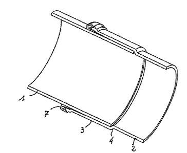
In Fig. 10 and 11, the pipe is a gutter, and not a pipe. The elements of Fig.
1 to 3, and 7
to 9, respectively, are used in a half-cylinder configuration.
The method of connection, by means of an injected assembly fluid, of two pipe
elements
for transport of fluid is implemented as follows in the case of figures 1 to
3, and it can
be transferred to the case of figures 7 to 11.
First of all, the diffusion part 7 is put in place on the edge 5 of the socket
3, being braced
against the limit stops 6, if necessary. Next, the set of the socket 3 and the
diffusion part
7 is inserted onto the end of the first pipe element 1, or instead the end of
the first pipe
element 1 is inserted into the set formed by the socket 3 and the diffusion
part 7 until
the end of the first pipe element 1 makes contact with the collar 4. The
reservoir 16 of
CA 02814608 2013-04-12
WO 2012/056315 PCT/1B2011/002705
9
assembly fluid is then connected, by its nozzle 18, to the opening 13 of the
diffusion
part 7 for diffusion of assembly fluid. The assembly fluid is then injected
into the
diffusion part 7, and it is distributed at first into the channel 14, around
the pipe. When
the channel 14 has been filled, the assembly fluid goes into the axial
channels 11 and
arrives at the space 12 between the first pipe element 1 and the socket 3.
As a variant, when the diffusion part 7 is composed of two complementary and
separable parts, the pipe element 1 is inserted into the socket 3 until the
end of the first
pipe element 1 makes contact with the collar 4. The diffusion part 7 is put in
place
around the pipe element 1 by assembling its 2 separable parts. The diffusion
part 7 is
then slid along the pipe element 1 toward the socket 3 until the outer wing 10
makes
contact with the limit stops 6 if necessary.
Since the secondary channel(s) 11 are basically more narrow than the
circumferential
channel 14, they only transmit the assembly fluid when the circumferential
channel 14 is
full, and the injection of assembly fluid to the space 12 occurs axially,
which ensures a
uniform injection and a good quality of injection.
As a variant, the secondary channels 11 can have a variable shape and
distribution about
the diffusion part 7 in order to distribute homogeneously the injected fluid
by making up
or increasing the head losses of the injected fluid.
The quantity of assembly fluid injected can be controlled by volumetric
dispensing, for
example, by means of the reservoir 16. The assembly fluid injected is an
assembly
and/or sealing product, preserved in liquid form in the reservoir 16, and it
can change its
state to become pastelike or solid under the action of air or a reagent.
The truncated cone shape of the socket 3 enables an adaptable play between the
pipe
element 1 and the socket 3 to allow an injection of assembly fluid with a
progressive
increasing of the injection pressure and a homogeneous distribution of
assembly fluid by
dynamic equilibration of the axial advancing front of assembly fluid.
CA 02814608 2013-04-12
WO 2012/056315 PCT/1B2011/002705
In the case when the diffusion part for diffusion of assembly fluid is in two
parts, it can
be removed after producing the connection for a possible reuse.
Figures 12 and 13 show another pipe connection according to yet another
embodiment
5 of the present invention.
The pipe connection comprises a first pipe element 21 adapted to be inserted
into a
second pipe element 22. The first pipe element 21 has a first connection end
211. The
second pipe element 22 has a second connection end 221, which is of similar
shape as
io the first connection end 211. Preferably, the first and second
connection ends 211, 221
are cylindrical. Of course, this is not limiting and other forms are possible
, such as
circular, polygon shaped.
The second connection end 221 has a socket 23, attached to the second pipe
element by
a collar 24. The second pipe element 22 and the second connection end 221 can
be
integrally formed as a one-diffusion part unitary member. Alternately, the
second pipe
element 22 and the second connection end 221 can be two distinct elements
connected
together, e.g.by gluing, welding, clipping or any other connection means.
The socket 23 has a free edge 25. The length of the socket 23 mainly
corresponds to the
insertion length of the first pipe element 21 into the second pipe element 22.
The length
of insertion of the first pipe element 21 into the second pipe element 22 may
be defined
by the length of the socket 23.
Due to the truncated shape of the socket 23, a space 212, referred to as the
connection
space, is formed between the socket 23 and the outer surface of the first pipe
element 21
inserted into the second pipe element. The space 212 is adapted to receive
assembly
fluid for the firm connection of the two pipe elements 21, 22.
A diffusion part 27 for diffusion of assembly fluid is provided. The diffusion
part 27 is
generally of annular shape, corresponding to the cylindrical outer shape of
the first and
CA 02814608 2013-04-12
WO 2012/056315 PCT/1B2011/002705
11
second connection ends 211, 221. Of course, this is not limiting and other
forms are
possible, to conform to the first and second connection ends 211, 221.
The diffusion part 27 is preferably of inverted U shape in cross section, and
adapted to
be placed on the pipe with the U shape in cross section along a plane passing
through
the main axis of the pipe. The diffusion part 27 comprises an inner wing 28, a
radial
body 29 and an outer wing 210. As shown on figure 12, the length of the inner
and outer
wings are mainly identical. Alternately, the inner wing and the outer wing can
have
varying lengths.
The inner wing 28 is adapted to be braced against the first pipe element 21
inserted into
the second pipe element 22. More precisely, the inner wing 28 has an outer
surface 281
in contact with the first pipe element 21, and an inner surface 282 for
receiving the free
edge 25 of the socket 23.
The inner surface 282 comprises a plurality of secondary channels 2110 (,
serving for
the axial deflection of the assembly fluid. As shown on figure 12, the
secondary
channels 2110 are axial and extend between a first channel end 2111 on the
radial body
side and a second channel end 2112 on the socket side. The inner surface 282
may be
fully or partly inclined or curved towards the connection space, adapted to
introduce an
axial speed to the assembly fluid and to direct the assembly fluid axially
towards said
connecting space.
The length of the secondary channels can correspond to the length of the inner
surface
282of the inner wing, or can have a length shorter than the inner wing 28. The
secondary
channels 2110 are aimed at deflecting the assembly fluid in the axial
direction, to allow
the transmission of the assembly fluid into the connection space 12 between
the socket
and the first tube element.
As will be explained later, the secondary channels 2110 are necessary for a
uniform
diffusion of the assembly fluid during injection.
CA 02814608 2013-04-12
WO 2012/056315 PCT/1B2011/002705
12
The free edge 25 of the second pipe element 22 is adapted to be inserted in
the diffusion
part 27, between the inner surface 282 of the inner wing 28 and the outer wing
210
when the diffusion part 27 for diffusion of assembly fluid is in place.
The diffusion part 27 comprises one or more openings 213 for the injection of
assembly
fluid. As seen on figure 10, the one or more openings 213 can be located on
the outer
wing 210. Of course, the one or more openings 213 could be located anywhere on
the
diffusion part 27, e.g. injection through the radial body 29 is also possible.
Between the free edge 25 of the socket 23, the radial body 29, the inner wing
28 and the
outer wing 10, a circumferential channel 214 is defined.
The circumferential channel 214 defines a space, which can be filled with
assembly
fluid injected into said diffusion part 27. This circumferential channel 24
communicates
with the one or more secondary channels 2110 formed in the inner surface 282
of the
inner wing 28. The circumferential channel 214 is adapted to act as a fluid
collector or
intermediary chamber for the diffusion of the assembly fluid in the different
axial
channels 2110.
Preferably, the circumferential channel 214 is wider than the secondary
channels 2110,
allowing the circumferential channel 214 to be filled with assembly fluid
first, and then
the diffusion of the assembly fluid in the axial channels 2110 and into the
connection
space 212.
The reservoir of assembly fluid 16 as shown on figure 6 can be used to inject
the
assembly fluid. The reservoir 16 has a flexible connection tube 17 provided
with a feed
nozzle 18, able to cooperate with the opening 213 of the diffusion part 27 to
ensure the
feeding of assembly fluid to the circumferential channel 214. As a variant,
the opening
13 of the diffusion part 27 can be arranged to cooperate directly with the
flexible
connection tube 17.
CA 02814608 2013-04-12
WO 2012/056315 PCT/1B2011/002705
13
The man skilled in the art will readily understand that the axial channels 11,
2110 are
preferably uniformly spaced apart circumferentially around the inner surface
of the inner
wing 8, 28, to allow a uniform repartition (distribution) of the injected
fluid.
Figures 1 and 12 show different spacings between the secondary diffusion
channels 11,
2110. The man skilled in the art will also understand that, even if the
diffusion channels
11, 2110 shown on the figures are substantially straight, any shape or
geometry can be
contemplated for the secondary channels.
DJ Further, the secondary diffusion channels 11, 2110 are axial diffusion
channels. In
another embodiment of the present disclosure as shown on figure 14, the
secondary
diffusion channels are radial channels. The secondary channel may also be
inclined with
respect to the axial direction and/or radial direction, or similar to a
partial
circumferential thread, as shown on figure 16.
Figure 14 shows elements of a pipe connection according to the present
disclosure. The
pipe connection comprises a first pipe element 31 adapted to be inserted into
a second
pipe element 32. The first pipe element 31 has a first connection end 311. The
second
pipe element 32 has a second connection end 321. Preferably, the first and
second
connection ends 311, 321 are cylindrical. Of course, this is not limiting and
other forms
are contemplated, such as circular, polygon shaped.
The second connection end 321 has a socket 33. The second pipe element 32 and
the
second connection end 321 can be integrally formed as a one-diffusion part
unitary
member. Alternately, the second pipe element 32 and the second connection end
321
can be two distinct elements connected together, e.g.by gluing, welding,
clipping or any
other connection means.
A diffusion part 37 for diffusion of assembly fluid is provided. The diffusion
part 27 is
generally of annular shape, corresponding to the cylindrical outer shape of
the first and
second connection ends 211, 221. Of course, this is not limiting and other
forms are
possible, to conform to the first and second connection ends 211, 221.
CA 02814608 2013-04-12
WO 2012/056315 PCT/1B2011/002705
14
The diffusion part 37 is preferably of inverted U shape in cross section, and
adapted to
be placed on the pipe with the U shape in cross section along a plane passing
through
the main axis of the pipe. The diffusion part 37 comprises an inner wing 38, a
radial
body 39 and an outer wing 310. As shown on figure 14, the inner wing 38 is
shorter than
the outer wing 310.
The inner wing 38 is adapted to be braced against the first pipe element 31
inserted into
the second pipe element 32. More precisely, in this embodiment, the inner wing
38 has
an inner surface 381 in contact with the first pipe element 31, an inner
surface 382 and
an end face 383 adapted to abut against the free edge 35 of the socket 33.
A circumferential channel 314 can be formed in the diffusion part 37 when the
diffusion
part is in place, the circumferential channel 314 being located between the
free edge 35
of the socket 33, the radial body 39, the inner wing 38 and the outer wing
310.
The end face 383 comprises a plurality of secondary channels 3110, serving for
the
deflection of the assembly fluid. As shown on figure 14, the secondary
channels 3110
are radial and extend between a first channel end 3111 on the outer surface
side and a
second channel end 3112 on the inner surface side of the inner wing 38..
The length of the secondary channels 3110 correspond to the width of the inner
wing 38.
The secondary channels 3110 are aimed at deflecting the assembly fluid from
the
circumferential channel 314, to allow the transmission of the assembly fluid
into the
connection space 12 between the socket and the first tube element.
The circumferential channel 314 defines a space, which can be filled with
assembly
fluid injected into said diffusion part 37. This circumferential channel 314
communicates with the one or more secondary channels 311 formed in the inner
wing
38. The circumferential channel 314 is adapted to act as a fluid collector or
intermediary
chamber for the diffusion of the assembly fluid in the different channels
3110.
CA 02814608 2013-04-12
WO 2012/056315 PCT/1B2011/002705
Preferably, the circumferential channel 314 is wider than the secondary
channels 3110,
allowing the circumferential channel 314 to be filled with assembly fluid
first, and then
the diffusion of the assembly fluid in the secondary channels 3110, and
ultimately into
the connection space between the socket and the first element.
5
The diffusion part 37 comprises one or more openings 313 for the injection of
assembly
fluid. The reservoir of assembly fluid 16 as shown on figure 6 can be used to
inject the
assembly fluid.
to Figure 15 show yet another pipe connection according to yet another
embodiment of the
present invention. The pipe connection of figure 15 mainly differs from the
pipe
connection of figure 14 in that the secondary diffusion channels are located
on the
socket instead of the diffusion part.
15 The pipe connection of figure 15 comprises a first pipe element 41
adapted to be
inserted into a second pipe element 42. The first pipe element 41 has a first
connection
end 411. The second pipe element 42 has a second connection end 421.
Preferably, the
first and second connection ends 411, 421 are cylindrical. Of course, this is
not limiting
and other forms are possible, such as circular, polygon shaped.
The second connection end 421 has a socket 43, which can be integrally formed
as a
one-diffusion part unitary member. Alternately, the second pipe element 42 and
the
second connection end 421 can be two distinct elements connected together,
e.g.by
gluing, welding, clipping or any other connection means.
A diffusion part 47 for diffusion of assembly fluid is provided. The diffusion
part 47 is
generally of annular shape, corresponding to the cylindrical outer shape of
the first and
second connection ends 411, 421. Of course, this is not limiting and other
forms are
possible, to conform to the first and second connection ends 411, 421.
The diffusion part 47 is preferably of inverted U shape in cross section, and
adapted to
be placed on the pipe with the U shape in cross section along a plane passing
through
CA 02814608 2013-04-12
WO 2012/056315 PCT/1B2011/002705
16
the main axis of the pipe. The diffusion part 47 comprises an inner wing 48, a
radial
body 49 and an outer wing 410.
The inner wing 48 is adapted to be braced against the first pipe element 41
inserted into
the second pipe element 42. More precisely, in this embodiment, the inner wing
48 has
an inner surface 481 in contact with the first pipe element 41, an outer
surface 482 and
an end face 483 adapted to abut against the free edge 45 of the socket 43 when
the
diffusion part and the socket are assembled.
A circumferential channel 414 can be formed in the diffusion part 47, the
circumferential channel 414 being located between the radial body 49, the
inner wing 48
and,the outer wing 410, and the end face 46 of the socket 43, when the
diffusion part 47
is in place.
The socket 43 comprises a plurality of secondary channels 4110, serving for
the
deflection of the assembly fluid. As shown on figure 15, the secondary
channels 4110
extend radially in the end face 46 of the socket 43 and axially on the inner
surface 431
adapted to face the first element when the first element is inserted into the
socket.
Although the secondary diffusion channels 4110 are extending both radially and
axially
on figure 15, the secondary diffusion channels may extend radially or axially
only.
The circumferential channel 414 defines a space, which can be filled with
assembly
fluid injected into said diffusion part 47. This circumferential channel 414
communicates with the secondary channels 4110 formed in the socket. The
circumferential channel 414 is adapted to act as a fluid collector or
intermediary
chamber for the diffusion of the assembly fluid in the different channels
4110.
Preferably, the circumferential channel 414 is wider than the secondary
channels 4110,
allowing the circumferential channel 314 to be filled with assembly fluid
first, and then
the diffusion of the assembly fluid in the secondary channels 311, and
ultimately into
the connection space between the socket and the first element.
CA 02814608 2013-04-12
WO 2012/056315 PCT/1B2011/002705
17
The diffusion part 47 comprises one or more openings 413 for the injection of
assembly
fluid. The reservoir of assembly fluid 16 as shown on figure 6 can be used to
inject the
assembly fluid.
It should be clear from the above description that the secondary diffusion
channels may
be radial and/or axial, as long as the secondary diffusion channels allow
directing of the
assembly fluid from the circumferential channel to the connection space
between the
socket and the first element.
Figure 16 shows elements of a pipe connection according to the present
disclosure. The
pipe connection of figure 16 mainly differs from the pipe connection as shown
on
figures 1 and 12 by the orientation of the secondary channels. The pipe
connection of
figure 16 comprises a first pipe element 51 adapted to be inserted into a
second pipe
element 52. The first pipe element 51 has a first connection end 511. The
second pipe
element 52 has a second connection end 521. The second connection end 521 has
a
socket 53. The second pipe element 52 and the second connection end with the
socket
53 can be integrally formed as a one-diffusion part unitary member.
Alternately, the
second pipe element 52 with the socket 53 can be two distinct elements
connected
together, e.g.by gluing, welding, clipping or any other connection means.
A diffusion part 57 for diffusion of assembly fluid is provided. The diffusion
part 57 is
generally of annular shape, corresponding to the cylindrical outer shape of
the first and
second connection ends 511, 521. Of course, this is not limiting and other
forms are
possible, to conform to the first and second connection ends.
The diffusion part 57 is preferably of inverted U shape in cross section, and
adapted to
be placed on the pipe with the U shape in cross section along a plane passing
through
the main axis of the pipe. The diffusion part 57 comprises an inner wing 58, a
radial
body 59 and an outer wing 510. As shown on figure 16, the length of the inner
wing 58
is mainly the same as the length of the outer wing 510. This is not limiting
and the inner
and outer wing can have varying lengths.
CA 02814608 2013-04-12
WO 2012/056315 PC171132011/002705
18
The inner wing 58 is adapted to be braced against the first pipe element 51
inserted into
the second pipe element 52. More precisely, the inner wing 58 has an inner
surface 581
adapted to be in contact with the first pipe element 51, an inner surface 582
for
receiving the socket 53.
A circumferential channel 514 can be formed in the diffusion part 57 when the
diffusion
part is in place, the circumferential channel 514 being located between the
free edge 55
of the socket 53, the radial body 59, the inner wing 58 and the outer wing
510.
= The inner surface 581 comprises a plurality of secondary channels 5110,
serving for the
deflection of the assembly fluid. As shown on figure 16, the secondary
channels 5110
have an axial component and extend partly circumferentially, similarly to a
thread. The
secondary channels 5110 are aimed at deflecting the assembly = fluid from the
circumferential channel 514, to allow the transmission of the assembly fluid
into the
connection space between the socket and the first tube element.
The circumferential channel 514 defines a space, which can be filled with
assembly
fluid injected into said diffusion part 57. This circumferential channel 514
communicates with the one or more secondary channels 5110 formed in the inner
wing
58. The circumferential channel 514 is adapted to act as a fluid collector or
intermediary
= chamber for the diffusion of the assembly fluid in the different channels
5110.
Preferably, the circumferential channel 514 is wider than the secondary
channels 5110..
= 25 The diffusion part 57 comprises one or more openings 513 for the
injection of assembly
fluid. The reservoir of assembly fluid 16 as shown on figure 6 can be used to
inject the
assembly fluid.
Figure 17 show yet another elements of a pipe connection, when assembled,
according
to yet another embodiment of the present invention. The pipe connection of
figure 17
CA 02814608 2013-04-12
WO 2012/056315 PCT/1B2011/002705
19
mainly differs from the pipe connection of figures 1-15 in that the socket and
the
diffusion part are integrally formed as a one part member.
The pipe connection of figure 17 comprises a first pipe element 61 inserted
into a
second pipe element 62. The first pipe element 61 has a first connection end
611. The
second pipe element 62 has a second connection end 621. Preferably, the first
and
second connection ends 611, 621 are cylindrical. Of course, this is not
limiting and other
forms are possible, such as circular, polygon shaped.
io The second connection end 621 has a socket 63, provided at a free end
with a diffusion
part 67 for diffusion of assembly. The diffusion part 67= defines a
circumferential
channel 614 located between a, radial body 69, an inner wing 68 and the outer
wing 610,
and the end face of the socket 43. In the embodiment of figure 16, the inner
wing 68 is
shorter than the outer wing 610, but this is not limiting. Further, the inner
wing 68 is
also provided with a gasket lip 680, preventing the assembly fluid from
leaking out of
the connection during injection. =
The socket 63 comprises a plurality of secondary channels 6110, serving for
the
deflection of the assembly fluid. As shown on figure 16, the secondary
channels 6110
extend radially and axially on the inner surface 631 facing the first element
inserted into
the socket.
The circumferential channel 614 defines a space, which can be filled with
assembly
fluid injected into said diffusion part 67. This circumferential channel 614
communicates with the secondary channels 6110 formed in the socket. The
circumferential channel 614 is wider than the secondary channels 6110 and is
adapted to
act as a fluid collector or intermediary chamber for the diffusion of the
assembly fluid in
the different channels 6110 and then into the connection space 612 between the
socket
and the first pipe element.
CA 02814608 2013-04-12
WO 2012/056315 PCT/1B2011/002705
The diffusion part 67 comprises one or more openings 613 for the injection of
assembly
fluid. The reservoir of assembly fluid 16 as shown on figure 6 can be used to
inject the
assembly fluid.
5
Figure 18 shows a method of connection of two pipe elements according to one
aspect
of the present invention, which can be used to connect two pipe elements for
transport
of liquid or gaseous fluid. The method of connection will be described in
conjunction
with pipe elements of figures 12-13.
In a first step Sl, the diffusion part is placed on the edge 25 of the socket
23 of the
second pipe element 22. The good positioning of the diffusion part may be
ensured by
the radial stop elements on the periphery of the socket 23. The diffusion part
may be
clipped on the socket, wherein clips may be provided on the socket and/or the
diffusion
part.
In a second step S2, the end of the first pipe element 21 is inserted into the
set formed
by said socket 23 and the diffusion part 27. The length of insertion of the
first pipe
element 21 into the second pipe element 22 may be defined by the length of the
socket
23 and the first pipe element is inserted until coming into abutment against
the collar 24.
A space 212, referred to as the connection space, is formed between the socket
23 and
the outer surface of the first pipe element 21 inserted into the second pipe
element. The
space 212 is adapted to receive assembly fluid for the firm connection of the
two pipe
elements 21, 22.
Alternately, the first pipe element 21 may be inserted into the diffusion part
27 first. The
= end of the first pipe element is thereafter inserted into the socket 23
and the diffusion
part 27. The length of insertion of the first pipe element 21 into the second
pipe element
22 may be defined by the length of the socket 23. The diffusion part 27 can
then be
braced against the edge of the socket of the second pipe element by sliding
said
diffusion part onto the first pipe element until the diffusion part 27
receives the edge 25
of the socket 23.=
CA 02814608 2013-04-12
WO 2012/056315 PCT/1B2011/002705
21
In a third step S3, once the pipe elements 21, 22 and the diffusion part 27
are in place,
the assembly fluid is injected into the diffusion part 27, through the
injection opening
213. The reservoir of assembly fluid 16 as shown on figure 6 can be used to
inject the
assembly fluid. The reservoir 16 has a flexible connection tube 17 provided
with a feed
nozzle 18, able to cooperate with the opening 213 of the diffusion part 27 to
ensure the
feeding of assembly fluid to the circumferential channel 214. As a variant,
the opening
23 of the diffusion part 27 can be arranged to cooperate directly with the
flexible tube
17.
During injection, the assembly fluid is first collected and distributed in the
circumferential channel 214, around the first pipe element 21. When the
circumferential
channel 214 is full, the assembly fluid diffuses into the axial channels 211
leading to the
space between said first pipe element 21 and the socket 23. The axial channels
2110
ensure a uniform axial diffusion of the assembly fluid in the axial direction
and into said
connection space 212.
Preferably, after completing the connection, the diffusion part for diffusion
of assembly
fluid is removed.