Note: Descriptions are shown in the official language in which they were submitted.
CA 02814887 2013-04-16
WO 2012/069505 PCT/EP2011/070739
1
Arrangement for manufacturing of portion packets
TECHNICAL FIELD
This invention relates to an arrangement for manufacturing of portion packets
of a product for oral use, which arrangement comprises a device for placing
the portion packets into a container.
BACKGROUND OF THE INVENTION
Manufacturing of portion packets of a smokeless product for oral use, such
as pouches filled with tobacco snuff or non-tobacco snuff, generally involve
the steps of (pre)treating and processing of the raw material (e.g. grounding,
adding salt and water, pasteurizing, mixing with additives, moistening, etc.),
forming portion-sized packets of the bulk material, wrapping a packaging
material, such as a standard cellulose based non-woven fabric for snus,
around the portion packets, and placing individual portion packets in a box or
container.
Examples of devices used in such manufacturing are disclosed in e.g. WO
2009/025604, EP 138649, EP 149985, WO 2009/047627 and SE 506146.
The step of placing the portion packets in a container has not been paid
much attention to in the past. Principally, a certain number of portion
packets
have simply been allowed to fall down in the container.
However, lately it has been paid some attention to the fact that portion
packets positioned in a certain pattern in the container provides a more
attractive appearance to the user. It has also been proposed that, by being
able of positioning the portion packets in the container, the portion packets
might be packed into the container in a more efficient way, both with regard
to time (production speed) and space (geometrically efficient packing).
2
How to achieve efficient positioning/packing of portion packets in large-scale
production is, however, not obvious because tobacco snuff or non-tobacco
snuff portion pack products are relatively difficult to handle in automated
processes (since they usually are soft and somewhat sticky) and because the
production rate is very high (typically several hundreds of portion packets
per
minute).
SUMMARY OF THE INVENTION
An object of this invention is to provide means for placing portion packets of
a
product for oral use, such as a tobacco snuff or a non-tobacco snuff product,
into a container, which device enables positioning of the portion packets in
the
container.
The invention concerns an arrangement for manufacturing of portion packets
of a product for oral use, said arrangement comprising a forming arrangement
configured to form portion packets of a bulk material.
The inventive arrangement is characterized in that it comprises a device for
placing the portion packets into a container, wherein the device comprises a
portion packet transporting unit and a portion packet positioning unit,
wherein
the transporting unit is configured to transport individual portion packets to
the positioning unit and wherein the positioning unit is configured to
position
the portion packets in a certain pattern during operation of the device,
wherein the transporting unit comprises a product channel intended for
transportation of the portion packets, said product channel having an inlet
and an outlet, wherein the transporting unit further comprises a gas channel
intended to be connected to a source of pressurized gas, wherein the gas
channel is arranged to, when connected to said source, guide pressurized
gas into the product channel in a direction towards the product channel
CA 2814887 2018-01-05
CA 02814887 2013-04-16
WO 2012/069505 PCT/EP2011/070739
3
outlet, and wherein the gas channel has an outlet opening positioned in the
product channel at a distance from the product channel inlet such that an
under-pressure is created at the product channel inlet when pressurized gas
is fed through said gas channel.
By creating an under-pressure (i.e. a pressure below that of the atmosphere)
at the inlet of the product channel a suction force is created that sucks the
portion packet into the product channel in a downstream direction towards
the point where the gas channel outlet opening is positioned at which point
the portion packet is further forced by the pressurized gas downstream
through the product channel towards the product channel outlet.
Due to this suction capability, portion packets can be transported in a
controlled and efficient way from various portion packet feeding
arrangements located before, or upstream of, the transporting unit in the
production line. By varying the pressure of the pressurized gas, the under-
pressure, i.e. the suction force, at the product channel inlet can be varied
in a
controllable manner and thereby be adapted to different conditions (e.g.
different portion packet properties)..
Moreover, by varying the pressure of the pressurized gas it is possible to, in
a controllable manner, vary the speed of the portion packet at the point
where it leaves the product channel outlet. This way the transporting unit of
the invention can be adapted to various types of portion packet positioning
units, or to the particular condition of a certain positioning unit.
In most situations a transporting unit of the inventive type will
significantly
increase the speed of the portion packet compared to the speed in the
feeding arrangement upstream of the transporting unit. Such an increase in
speed means that the distance between the individual portion packets will
increase. This makes in turn the job easier for the positioning unit since it
may occupy more space during the time interval between two incoming
CA 02814887 2013-04-16
WO 2012/069505 PCT/EP2011/070739
4
portion packets (compared to the situation where the speed has not been
increased and where, accordingly, the distance between a rear part of a first
portion packet and a front part of a second, following, portion packet is
shorter). And if the job is easier for the positioning unit it becomes easier
to
come up with a design that works properly.
Using only compressed gas (over-pressure) for transporting the portion
packets, e.g. by discharging pressurized air at the product channel inlet,
gives rise to a complicated flow pattern that in turn makes it much more
difficult to control the transport of the portion packets, both with regard to
the
timing and the speed of the transport. Besides that the inventive concept
provides for a more controllable transport than the use of over-pressure only,
it is also less energy-intensive since the losses are smaller. Further, the
transporting does not rely on moving parts, such as conveyor belts, which
makes it more reliable.
A controlled transport of the portion packets is of paramount importance for
allowing the positioning unit to work properly, irrespectively of the exact
design of the positioning unit. Even small variations in timing or speed in
the
transport of the portion packets are likely to lead to clogging and thereby
interruptions in the production process.
In an embodiment of the invention the gas channel is arranged such that,
when pressurized gas is discharged from the gas channel outlet opening into
the product channel, the gas exhibits an initial direction of flow that forms
an
angle a that is less than 30 , preferably less than 15 , in relation to a
longitudinal direction of the product channel.
In an embodiment of the invention the gas channel outlet opening is
positioned at a distance also from the product channel outlet and that the
product channel is substantially straight between the position of the gas
channel outlet opening and the product channel outlet.
CA 02814887 2013-04-16
WO 2012/069505 PCT/EP2011/070739
In an embodiment of the invention the product channel has a width and
height that is 1-15% larger than a width and thickness of the portion packet
to
be transported.
5
In an embodiment of the invention the ratio between the area of the gas
channel outlet opening 17 and the cross-sectional area of the product
channel 12 is in the interval of 0.02-0.2, preferably in the interval of 0.05-
0.15.
In an embodiment of the invention the positioning unit comprises a set of
portion packet receiving compartments arranged in a certain pattern, each of
said compartments having an entrance end allowing a portion packet to enter
the compartment and, at an opposite side of the compartment, a retaining
end preventing a portion packet from exiting the compartment in that
direction, wherein the positioning unit further comprises a discharging
member configured to discharge portion packets from the compartments to
the container, wherein the compartments are associated with a supporting
structure that retains the compartment pattern during operation of the device.
In such a device the portion packets can be fed in various ways to the
compartments where they will remain until the discharging member is used to
transfer the portion packets into the container. Since the compartments are
arranged in a certain pattern, e.g. circumferentially distributed in a
circular
manner, also the portion packets will be arranged in a corresponding pattern
when positioned in the compartments. Due to fixing and retaining properties
of the supporting structure, that fixes the shape of the compartments and
retains the pattern during operation of the device, the portion packet pattern
is retained also when discharging the portion packets from the compartments
into the container. The same pattern can be retained for the portion packets
when transferred to the container, for instance by adapting the size and
CA 02814887 2013-04-16
WO 2012/069505 PCT/EP2011/070739
6
shape of the container to that of the initial portion packet pattern and by
handling the container properly after it has been filled.
Thus, instead of organizing the portion packets during the step of placing
them into the container or when they actually have been placed in the
container, the portion packets are positioned in a certain pattern already
when they have entered the compartments, i.e. before the step of transferring
them into the container. Such a process is suitable for automation and a high
production rate because it is more reliable and creates a period of time
suitable for positioning of the next container to be filled.
This embodiment of the invention makes use of a supporting structure that
keeps the compartments in a fixed position in relation to each other so as to
retain the pattern during operation of the device. This way it is possible to
reduce the number of moving parts compared to, for instance, solutions
involving one or several conveyor belts, which can be used to improve the
reliability of the device. A further advantage of the present invention is
that
the compartments do not narrow before discharge as is normally the case
for, for instance, conveyor belt-solutions where products are retained
between separating walls fastened to the belt. Typically, the products are
loaded when the belt turns around a pulley - which causes the walls to
separate from each other - and unloaded at a straight part of the conveyor
belt - where the walls are parallel. Such a narrowing can lead to clamping of
the product and make discharge problematic.
In an embodiment of the invention each of said compartments comprises a
first and a second wall member arranged at an angle in relation to each other
such as to form a wedge-shaped structure, wherein the wider end of the
wedge-shaped structure forms the compartment entrance end.
In an embodiment of the invention the transporting unit and the portion
packet receiving compartments are movable in relation to each other such
CA 02814887 2013-04-16
WO 2012/069505 PCT/EP2011/070739
7
that the entrance end of each of the compartments can be directed towards
the transporting unit.
In an embodiment of the invention the compartments are arranged side-by-
side such that a single wall member forms a dividing wall between two
adjacent compartments.
In an embodiment of the invention the supporting structure is moveably
suspended in the positioning unit such that the entrance ends of the
compartments can be positioned in different directions and/or positions by
moving the supporting structure. By controlling this movement the
compartments can be filled with portion packets fed to the portion packet
positioning unit, for instance by controlling the movement in a stepwise
manner and loading portion packets one by one. Preferably, the supporting
structure is rotationally and/or transversally suspended in the positioning
unit
such that the direction/position of an entrance end of a compartment can be
varied by rotating and/or transversally moving the supporting structure. The
term "transversally" refers to the transport direction in which portion
packets
are fed to the positioning unit. Thus, the transversal direction is typically
perpendicular to the transport direction.
In an embodiment of the invention the discharge member comprises an
ejector element that has a shape that corresponds with the pattern of
compartments such that the ejector element, when activated, is capable of
ejecting portion packets present in each of the compartments.
In an embodiment of the invention the discharge member is configured to
discharge portion packets from each of the compartments in a direction that
is substantially perpendicular to a direction corresponding to a straight line
connecting the entrance and retaining ends of the compartment, i.e.
sideways in a direction perpendicular to the direction in which the portion
packets have entered the compartment.
CA 02814887 2013-04-16
WO 2012/069505 PCT/EP2011/070739
8
The invention also refers to an arrangement for manufacturing of portion
packets of a product for oral use, which arrangement comprises a device of
the above type.
In an embodiment of the invention the arrangement comprises a forming
arrangement configured to form portion packets of a bulk material.
In an embodiment of the invention the arrangement comprises a packaging
arrangement configured to wrap a packaging material around individual
portion packets, wherein said packaging arrangement is arranged upstream
of the transporting unit so that portion packets fed to the transporting unit
are
wrapped in said packaging material.
BRIEF DESCRIPTION OF DRAWINGS
In the description of the invention given below reference is made to the
following figure, in which:
Figure 1 shows a first embodiment of the inventive device,
Figure 2 shows a similar view as figure 1 but with containers added,
Figure 3 shows, in a partly sectional view, the embodiment according to
figure 1,
Figure 4 shows a similar view as figure 3 but at another stage of the
manufacturing process,
Figure 5 shows, in a partly sectional view, parts of the embodiment
according to figure 1,
Figure 6A shows a variant of the positioning unit of the inventive device,
Figure 6B shows a sectional view of figure 6A,
Figure 7 shows a second embodiment of the inventive device including
the variant of figures 6A and 6B,
Figure 8 shows parts of the second embodiment according to figure 7,
Figure 9 shows a sectional view of some of the parts shown in figure 8,
CA 02814887 2013-04-16
WO 2012/069505 PCT/EP2011/070739
9
Figure 10 shows, in a first position, a preferred embodiment of a container
holding arrangement of the inventive device, and
Figure 11 shows the container holding arrangement of figure 10 in a
second position.
DESCRIPTION OF EXAMPLE EMBODIMENTS OF THE INVENTION
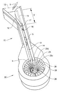
Figure 1 shows a first embodiment of the inventive device 1 for placing
portion packets 5 of a product for oral use into a container 7. In this case
the
portion packets are pouches filled with tobacco snus or non-tobacco snus.
As can be seen in figure 1, the device 1 comprises a portion packet feeding
arrangement 3, a portion packet transporting unit 10 and a portion packet
positioning unit 20, wherein the feeding arrangement 3 is configured to feed
portion packets 5 to the transporting unit 10, wherein the transporting unit
10
is configured to transport individual portion packets 5 to the positioning
unit
and wherein the positioning unit 20 is configured to position the portion
packets 5 in a certain pattern during operation of the device 1.
In this example the transporting unit 10 and the positioning unit 20 are
20 arranged in such a way as to form what can be regarded as one integrated
unit.
The transporting unit 10 is further described below in relation to figures 3
and
5. The positioning unit 20 is further described below in relation to figures 3-
5.
A design of an alternative positioning unit 200 is shown in figures 6-9.
As shown in figure 1, the positioning unit 20 comprises, for instance, a set
of
portion packet receiving compartments 25 arranged side-by-side in a circular
pattern, wherein said compartments 25 in this case are formed by wall
members 26 arranged at an angle in relation to each other such as to form a
wedge-shaped compartment 25 between each pair of wall members 26. The
CA 02814887 2013-04-16
WO 2012/069505 PCT/EP2011/070739
positioning unit 20 further comprises a discharging member of which a
cylinder 21 and an ejection pin 22 are shown in figure 1.
The device 1 shown in figure 1 forms part of an arrangement for
5 manufacturing of portion packets 5 of a product for oral use. In addition
to
what is shown in figure 1, this manufacturing arrangement comprises a
processing arrangement configured to process a bulk material, which in this
example is based on a tobacco or non-tobacco material. The manufacturing
arrangement further comprises a forming arrangement configured to form the
10 portion packets 5 of the bulk material. Further, the manufacturing
arrangement comprises a packaging arrangement configured to wrap a
packaging material around individual portion packets such as to form
pouches. The packaging arrangement is arranged upstream of the
transporting unit 10 and of the feeding arrangement 3 so that portion packets
5 fed to the transporting unit 10 are wrapped in said packaging material.
Manufacturing processes of smokeless tobacco products for oral use, e.g.
moist snuff such as snus, and chewing tobacco, are well known to the person
skilled in the art, and any known process thereof may be used. Moist snuff is
known as either Swedish-type snus or American-type moist snuff.
A general description of snus manufacturing is presented by e.g. ESTOC,
European Smokeless Tobacco Council, and the GothiaTek quality standard
for snus. Methods for the manufacture of American type moist snuff and
chewing tobacco are described in e.g. Wahlberg, I., Ringberger, T. (1999)
Smokeless Tobacco. In: Tobacco: Production, Chemistry and Technology,
(eds D.L. Davis & M.T. Nielsen) pp. 452-460. World Agriculture Series,
Blackwell Science Ltd. Tobacco is the raw material in any oral smokeless
tobacco product. However, for the reason of controlling the nicotine content
of the products, the raw material may well be constituted of a mixture of
tobacco and other plant materials.
CA 02814887 2013-04-16
WO 2012/069505 PCT/EP2011/070739
11
The principle of snus manufacturing is to mix ground or cut tobacco with
water and sodium chloride and heat treating the mixture for a period of time
long enough (typically several hours), and at a temperature high enough, to
meet the demands for pasteurization. The heat treatment also gives texture
and color to the mixture and enhances the natural tobacco flavors. After heat
treatment the mixture is chilled. Additives such as pH-regulators and
flavourings are then added and the mixture may be adjusted in moisture
content.
American-type moist snuff is commonly produced through a fermentation
process of moisturized ground or cut tobacco. Flavors and ingredients are
mixed to the blend and water is added to adjust the moisture content.
Chewing tobacco is most often made of loose leaf tobacco, which is cured at
a slightly elevated temperature. The tobacco leaves are then threshed into
flakes and the mid-rids (stems) are removed. The tobacco fragments thus
obtained are usually treated with a solution of flavors and additives, dried
to
lower the moisture content and packed in a consumer package. The product
achieved is known as "loose-leaf chewing tobacco".
Hard snuff is a group of oral tobacco-based products intended for oral use as
a delivery system of nicotine from tobacco. Besides the additive carrying the
active substance, which is tobacco carrying nicotine, hard snuff products are
generally constituted by entirely or substantially inert materials such as
fibres
and polymers. They may also be mainly constituted by powdered tobacco.
Dry oral snuff resembles snus and American-type moist snuff but is
characterized by being made of a finely ground tobacco powder and having a
low moisture content (typically less than 10%). The product may be heat
treated but is normally manufactured from fire-cured fermented tobacco
which is ground into a powder to which other ingredients such as flavors are
added.
CA 02814887 2013-04-16
WO 2012/069505 PCT/EP2011/070739
12
Manufacturing of oral smokeless non-tobacco snuff products typically follows
the procedure of manufacturing of oral smokeless tobacco products, with the
obvious difference that tobacco is replaced by non tobacco raw material,
typically constituted of non-tobacco plant materials.
Any known type of oral smokeless tobacco or oral non-tobacco product may
be used as a bulk material in the portion packets.
The principal structure and function of the feeding, processing, forming and
packaging arrangements are well known to a person skilled in the art. These
arrangements may be arranged in different ways and are not further
described here.
Figure 2 shows a similar view as figure 1, but figure 2 also shows containers
7 and a container holding arrangement 8. This arrangement 8 is configured
to hold the container 7 in a certain position in relation to the positioning
unit
such as to allow portion packets 5 placed in the compartments 25 to be
discharged into the container 7. The container holding arrangement 8
controls the movement of the containers 7 in relation to the compartments 25
20 such as to allow positioning of each of the containers 7, one by one, in
connection to the compartments 25. An open end of the containers 7 is
facing towards the compartments 25. In figure 2 the container holding
arrangement 8 is only depicted schematically. A person skilled in the art is
aware of that the container holding arrangement 8 can be arranged in
different ways. A preferred embodiment of the container holding arrangement
is shown in figures 10-11.
Figure 3 shows, in a partly sectional view, the embodiment according to
figure 1. Figure 3 shows the device 1 during operation where a portion packet
5 fed to the transporting unit 10 is transported in a controlled way via a
product channel 12 to an empty portion packet receiving compartment 25 in
the positioning unit 20. Some portion packets 5 have already been positioned
CA 02814887 2013-04-16
WO 2012/069505 PCT/EP2011/070739
13
in the positioning unit 20, i.e. some of the compartments 25 already contain a
portion packet 5. Further portion packets 5 are positioned in the feeding
arrangement 3 on their way towards the transporting unit 10.
Each of the receiving compartments 25 has an entrance end 25a allowing a
portion packet 5 to enter the compartment 25 and, at an opposite side, a
retaining end 25b preventing the portion packet 5 from exiting the
compartment 25 in that direction (see also figure 5). Each compartment 25 is
formed by first and second wall members 26 arranged at an angle in relation
to each other such as to form a wedge-shaped structure, wherein the wider
end of the wedge-shaped structure forms the compartment entrance end
25a. In this case the compartments 25 are distributed side-by-side in a
circular pattern with their entrance ends 25a directed outwards from the
circle
and their retaining ends 25b directed inwards towards a centre of the circle.
Each wall member 26 extends in a radial and an axial direction of the circular
pattern and forms a common wall of two adjacent compartments 25.
The transporting unit 10 and the positioning unit 20 are arranged in relation
to
each other in such a way that an outlet 14 of the product channel 12 of the
transporting unit 10 is directed towards the entrance end 25a of the portion
packet receiving compartment 25. Further, the product channel 12 has a
rectangular cross section adapted to a width and a thickness (height) of the
portion packets 5 (wherein the width in this case is greater than the
thickness/height, see also below) and the transporting unit 10 and the
positioning unit 20 are arranged in relation to each other also in such a way
that the width direction of the product channel 12 is substantially parallel
with
the wall members 26 of a receiving compartment 25 having its entrance end
25a directed towards the outlet 14 of the product channel 12.
As seen in figure 3 the wall members 26 are attached to a supporting
structure 27, which in turn is attached to a rotation controlling member 24 in
the form of a first gear wheel. The wall members 26, the supporting structure
CA 02814887 2013-04-16
WO 2012/069505 PCT/EP2011/070739
14
27 and the first gear wheel 24 are rotationally suspended by means of a
bushing 31. The first gear wheel 24 is operatively connected to a second
gear wheel 29 that is connected to a driving motor (not shown). By controlling
the motor the rotation of the portion packet receiving compartments 25, in
relation to the outlet 14 of the product channel 12, can be controlled. This
rotation is indicated with an arrow 34.
Accordingly, the transporting unit 10 and the portion packet receiving
compartments 25 are movable in relation to each other such that the
entrance end 25a of each of the compartments 25 can be moved such as to
be directed towards the transporting unit 10. In this example the
compartments 25 are attached to the supporting structure 27 that is
rotationally suspended in the positioning unit 20 such that the entrance end
25a of the compartments 25 can be directed in different directions by rotating
the supporting structure 27.
The ejection pin 22 extends through the bushing 31 and is connected to an
ejection element 28 that has a shape that corresponds with the pattern of
compartments 25 and that is moveable in relation to the compartments 25 in
a direction parallel to the wall members 26 and perpendicular to the direction
in which the portion packets 5 enter the compartments 25. In other words, in
the example shown in figures 1-5 the ejection element 28 is moveable in
relation to the compartments 25 in an axial direction of the circular pattern.
Thus, the ejection pin 22 is, via the ejection element 28, capable of ejecting
each portion packet 5 placed in the compartments 25 in a sideways manner
(in relation to the direction in which the portion packet 5 has entered the
compartment 25).
The ejection element 28 has in this case a number of parts protruding in a
radial direction from a central part. This number corresponds to the number
of receiving compartments 25 and each of said radially protruding parts has a
shape corresponding to that the corresponding compartment 25.
CA 02814887 2013-04-16
WO 2012/069505 PCT/EP2011/070739
The other end of the ejection pin 22, i.e. the left end in figure 3, is
connected
to a piston (not shown) in the cylinder 21. The position of the piston can be
controlled pneumatically or hydraulically which, as such, is well known to the
5 person skilled in the art. By controlling the piston as to move towards
the
compartments 25 as indicated by the arrow 33 in figure 3, i.e. by activating
the discharge member, the ejection pin 22 and the ejection element 28 will
move in the same direction resulting in that portion packets 5 present in the
compartments 25 will be ejected (and placed in the same pattern in the
10 container 7 if this is properly positioned at the positioning unit 20).
An outer
side of each compartment 25, i.e. the side facing the container 7, is open as
to allow the portion packets 5 to be ejected in that direction.
As described more in detail below, the portion packets 5 are driven by
15 pressurized gas, in this case air, through the product channel 12
towards the
positioning unit 20. When the portion packet 5 has left the transporting unit
10 and reaches an empty receiving compartment 25 in the positioning unit 20
it will stop in the compartment 25 when the retaining end 25b prevents the
portion packet 5 from moving further.
At that point the supporting structure 27 and the associated set of
compartments 25 are rotated one step, by activating the driving motor, so
that the next compartment 25 becomes directed towards the transporting unit
10. When a next portion packet 5 has passed the transporting unit 10 and
has been positioned in the next compartment 25 the set of compartments 25
are rotated one step again. This is then repeated until all compartments 25
contain a portion packet 5, which portion packets 5 are positioned in the
circular pattern corresponding to that of the compartments 25.
At that point, a suitably shaped container 7 has been positioned in front of
the
positioning unit 20 such as to be ready for being filled with portion packets
5
of this pattern. To transfer the portion packs 5 into the container 7 the
CA 02814887 2013-04-16
WO 2012/069505 PCT/EP2011/070739
16
discharge member is activated. This means that the ejection pin 22 and the
ejection element 28 is moved towards the container 7 which forces the
portion packs 5 out from compartments 25, via its open side, into the
container 7.
The portion packets 5 enter the positioning unit 20 in a first direction and
are
ejected in a second direction that is substantially perpendicular to the first
direction. Thus, the portion packets 5 are ejected with their side first
towards
the container 7.
Figure 4 shows the situation when the discharge member has been activated
so that the portion packs 5 have been transferred to the container 7 where
they are positioned with their side towards a bottom of the container 7 (which
is placed on its edge or side) in the pattern defined by the pattern of the
compartments 25. The pattern formed of the compartments 25 has a circular
cross section corresponding to that of the container 7 used. During the step
of discharging the portion packets 5 into the container 7 feeding of further
portion packets 5 to the transporting unit 10 may be interrupted for a certain
time interval. An arrow 33' indicates the intended direction of the ejection
pin
22 and the ejection element 28 when the discharge member is deactivated
so as to continue the process of filling the compartments 25 with further
portion packets 5.
Figure 5 shows, in a partly sectional view, the transporting unit 10 and parts
of the positioning unit 20. One portion packet 5 is positioned at an inlet 13
of
the product channel 12, another portion packet 5 is positioned in the product
channel 12 on its way towards an empty compartment 25, and a few portion
packets 5 have already been positioned in their compartments 25. Besides
wall members 26 and the entrance and retaining ends 25a, 25b of the
compartments 25, the ejection element 28 can be seen in figure 5. It can also
be seen that there is an opening in the retaining end 25b of the
compartments 25. This opening is adapted such as to allow a part of the
CA 02814887 2013-04-16
WO 2012/069505 PCT/EP2011/070739
17
portion packet 5 to protrude out from the retaining end 25b when positioned
in the compartment 25. This allows the portion packets 5 to come very close
to each other in a central point of the circular pattern (and in the container
7).
In addition, the centrally located void these openings give rise to allows the
radially protruding parts of the ejection element 28 to be connected in the
radial direction to a central part of the ejection element 28 (or directly to
the
ejection pin 22 if this extends to this position).
In the absence of such a void, i.e. in the case where the wall members 26
meet at a central point of the circular pattern, the protruding parts can be
connected directly or indirectly to the ejection pin 22 at a position closer
to
the bushing 31, e.g. inside the supporting structure 27 (which does not have
to be a solid part). In such a case the protruding parts of the ejection
element
28 must extend sufficiently in the axial direction of the circular pattern so
as
to be capable of ejecting the portion packets 5 properly.
As mentioned above the transporting unit 10 comprises a product channel 12
having an inlet 13 and an outlet 14, which product channel 12 is intended for
transportation of the portion packets 5. As seen in figure 5, the transporting
unit 10 further comprises a gas channel 15 intended to be connected to a
source (not shown) of pressurized gas, typically air. This gas channel 15 is
arranged to, when connected to said source, guide pressurized gas into the
product channel in a direction (arrow 16) towards the product channel outlet
14.
The gas channel 15 has an outlet opening 17 positioned in the product
channel 12 at a distance D from the product channel inlet 13 such that an
under-pressure is created at the product channel inlet 13 when pressurized
gas is fed through said gas channel 15. Further, the gas channel 15 is
arranged such that, when pressurized gas is discharged from the gas
channel outlet opening 17 into the product channel 12, the gas exhibits an
initial direction of flow that forms an angle a that is close to zero in
relation to
CA 02814887 2013-04-16
WO 2012/069505 PCT/EP2011/070739
18
a longitudinal direction of the product channel 12. To create a suitable under-
pressure, the angle a should be less than 300, preferably less than 15 .
The distance D may be varied; the gas channel outlet opening 17 may be
positioned closer to the product channel outlet 14 than shown in figure 5. The
important thing is to create an under-pressure at the inlet 13 so that the
portion packets 5 are sucked into the product channel 12. Therefore the
distance D must not be too short. The minimum value of the distance D
depends on the application and is therefore difficult to quantify in general
terms. As a guideline the minimum value of the distance D can be set equal
to the width of the product channel 12. As a general recommendation the
distance D should be at least 2-3 times the minimum value to ensure a
favourable flow pattern at the product channel inlet 13.
As mentioned above, use of under-pressure for transporting portion packets
5 to the positioning unit 20 provides for a controlled transport of the
portion
packets 5, which is of importance for the function of the positioning unit 20.
Moreover, it provides for a more energy efficient production process
(compared to the alternative of supplying pressurized gas to the inlet 13 for
pushing/pressing the portion packet 5 into the product channel 12).
In this example the gas channel outlet opening 17 is positioned at a distance
also from the product channel outlet 14 and the product channel 12 is
substantially straight between the position of the gas channel outlet opening
17 and the product channel outlet 14.
To enhance the direction of the gas flow, the gas channel outlet opening 17
is arranged substantially in the center of the product channel 12. In order to
allow for such a positioning of the outlet opening 17, the product channel 12
exhibits a curved path upstream of the position of the gas channel outlet
opening 17.
CA 02814887 2013-04-16
WO 2012/069505 PCT/EP2011/070739
19
As an alternative to what is shown in figure 5, the product channel 12 can be
straight all the way from the inlet 13 to the outlet 13 with gas fed to the
product channel 12 at a small angle a.
The gas channel 15 can be very short and can in principle consist only of the
outlet opening 17.
The length of the product channel 12 can be adapted to the particular
application. To have full control of the transportation of the portion packet
5 it
is normally an advantage if only one portion packet 5 at a time is present in
the product channel 12.
As mentioned above, the product channel 12 has a rectangular cross section
adapted to the width and thickness of the portion packets 5 in question.
Normally, a suitable width and height of the product channel 12 is 1-15%
larger than the width and thickness of the portion packet 5. As an example,
the product channel 12 can have a width of 20 mm and a height of 7 mm.
Upstream of the gas channel outlet opening 17 the product channel 12
widens towards the inlet 13 to facilitate the entrance of the portion packet
5.
By varying the pressure of the gas fed to the gas channel 15, the under-
pressure (i.e. the suction force) at the product channel inlet 13 can be
varied
in a controllable manner and thereby be adapted to different conditions, e.g.
to different properties of the portion packets 5. Moreover, by varying the
pressure of the pressurized gas it is possible to, in a controllable manner,
vary the speed of the portion packet 5 at the point where it leaves the
product
channel outlet 14.
It is important to create a sufficient under-pressure at the inlet 13 of the
product channel 12 so that the intake and transport of the portion packet 5
can be thoroughly controlled. Generally, the level of under-pressure at the
inlet 13 depends on the position of the gas channel outlet opening 17 (both
CA 02814887 2013-04-16
WO 2012/069505 PCT/EP2011/070739
longitudinally and transversely in relation to the product channel 12), the
angle a formed between the initial direction of the gas flow and the
longitudinal direction of the product channel 12, the ratio between the area
of
the gas channel outlet opening 17 and the cross-sectional area of the product
5 channel 12, as well as the pressure of the gas fed to the gas channel 15.
As discussed above the longitudinal position of the outlet opening 17 is
normally not critical as long as there is a sufficient distance D between the
opening 17 and the product channel inlet 13. As to the transversal positioning
10 of the opening 17 it is generally better to have a central location of
the
opening 17 to obtain a more uniform gas flow. As to the angle a: the smaller
the angle, the better the under-pressure. An angle a of up to around 15 does
only slightly deteriorate the under-pressure at the product channel inlet 13.
At
angles larger than 300 the under-pressure is considerably deteriorated.
As to the area ratio and the gas pressure the relationship is more
complicated. The pressure at the product channel inlet 13 plotted as a
function of the area ratio forms a U-shaped function. Thus, at a certain
optimum value of the area ratio the pressure at the inlet 13 reaches a
minimum value (i.e. the under-pressure reaches a maximum value). This
function also depends on the pressure of the gas fed to the gas channel 15.
When increasing the gas pressure the U-shaped curve becomes steeper and
its minimum value moves towards a lower value of the area ratio. For
instance, using a gas pressure of 3 bar the optimal value of the area ratio
(i.e. the ratio between the area of the gas channel outlet opening 17 and the
cross-sectional area of the product channel 12) for reaching the lowest
pressure at the product channel inlet 13 is 0.13-0.14.
However, it is not necessary to operate exactly at these optimum points of
the pressure curves. Since the U-shaped curves are reasonably flat the
under-pressure can be kept at a suitable level even if the gas pressure is
varied within reasonable limits and even if the transporting unit 10 is not
CA 02814887 2013-04-16
WO 2012/069505 PCT/EP2011/070739
21
operated with an optimal area ratio for a given gas pressure. Generally, an
area ratio in the interval of 0.02-0.2 is suitable for a gas pressure of 3-6
bar.
For gas pressures of 3-4 bar the under-pressure is reasonable even for
larger area ratios. An area ratio in the interval of 0.05-0.15 is more
suitable
for a gas pressure of 3-6 bar. Which area ratio to choose depends on the
application (e.g. the required magnitude of the under-pressure and the gas
pressure(s) to be used).
Figures 6-9 show an alternative positioning unit 200 of the inventive device
1.
In similarity to what is described above, portion packet receiving
compartments 225, each of which having an entrance end 225a and a
retaining end 225b, are formed by wall members 226 arranged in a wedge-
shaped structure, see figures 6A and 6B. Also in this case a single wall
member 226 forms a separating wall between two adjacent compartments
225. However, in the variant shown in figures 6-9 the compartments 225 are
arranged side-by-side in a first and a second row wherein adjacent
compartments 225 have their entrance ends 225a facing in opposite
directions, i.e. wherein adjacent compartments 225 belong to different rows.
The wall members 226 are arranged in a rotatable supporting structure 227.
Figure 7 shows an inventive device 1 equipped with a positioning unit 200
according to figure 6. The transporting unit 10 is similar to what is
described
above. Also in this case the positioning unit 200 comprises a cylinder 221, an
ejection pin 222 (which is connected to a piston located inside the cylinder
221) and a rotation controlling member 224 arranged to control a rotation of
the rotationally suspended supporting structure 227. The rotation controlling
member 224 comprise a controllable motor and can comprise additional
gearings.
The positioning unit 200 shown in figures 6-9 also comprises a transversal
movement controlling arrangement 223, where the term transversal relates to
the direction of the portion packets 5 when transported through the
CA 02814887 2013-04-16
WO 2012/069505 PCT/EP2011/070739
22
transporting unit 10 and into the positioning unit 200. As shown in figures 7-
9
the transversal movement controlling arrangement 223 comprises a geared
member 223b connected to the supporting structure 227 and extending along
the supporting structure 227 in a direction parallel to the rows of receiving
compartments 225, a gear wheel 223a and a controllable motor 223c,
wherein the gear wheel 223a is operatively connected to both the geared
member 223b and the motor 223c.
The supporting structure 227 is not only rotationally suspended but also
arranged to be moveable in the direction of extension of the rows of
compartments 225. By controlling the transversal movement controlling
arrangement 223 it is possible to move the supporting structure 227
sideways (in relation to the transporting unit 10) in a step-by-step manner so
that each of the compartments 225 in the first row of compartments becomes
aligned with the product channel 12 with its entrance end 225a facing the
outlet 14 of the product channel 12. When portion packets 5 are fed to the
transporting unit 10 they can now be further fed to each of the compartments
225 in the first row. By controlling the rotation controlling member 224 it is
possible to rotate the supporting structure 227 180 so that the second row of
compartments 225 can be filled in the same step-wise manner.
Figure 8 shows the positioning unit 200 in a perspective view from behind.
This figure clearly shows the discharging member of the positioning unit 200,
which discharging member, in similarity to the positioning unit 20 described
above, comprises a cylinder 221, an ejection pin 222 and an ejection element
228. The ejection element 228 comprises a number of parts protruding from
a supporting part 228a towards the supporting structure 227. The number of
protruding parts corresponds to the number of portion packet receiving
compartments 225 and each of said protruding parts has a shape
corresponding to that of the corresponding compartment 225. Thus the
ejection element 228 has a shape that corresponds with the pattern of the
compartments 225, which in this case is rectangular (which calls for the use
CA 02814887 2013-04-16
WO 2012/069505 PCT/EP2011/070739
23
of a corresponding rectangular container (not shown) in contrast to the
circular container described above).
Figure 9 shows parts of the positioning unit 200 in a partly sectional
perspective view from the front side. This figure shows, for instance, that
the
cross section of the protruding parts of the ejection element 228 corresponds
to the cross section of the compartments 225.
The supporting part 228a of the ejection element 228 is connected to the
ejection pin 222 which, in line with what is described above, in turn is
connected to a piston (not shown) in the cylinder 221. The position of the
piston can be controlled as described above. By controlling the piston as to
move in relation to the supporting structure 227 and its compartments 225 as
indicated by the arrow 233 in figures 8 and 9õ i.e. by activating or
deactivating the discharging member, the ejection element 28 can be moved
towards the supporting structure 227 such as to eject portion packets 5
present in the compartments 225 (and place them in the same pattern in a
container properly positioned at the positioning unit 200) and moved away
from the supporting structure 227 to allow re-filling of the portion packet
receiving compartments 225. An outer side of each compartment 225, i.e. the
side facing away from the ejection element 228, is open as to allow the
portion packets 5 to be ejected in that direction.
The function of the positioning unit 200 shown in figures 6-9 is in principal
the
same as for the unit 20 shown in figures 1-5. A general feature is that the
transporting unit 10 and the portion packet receiving compartments 25, 225
are movable in relation to each other such that the entrance end 25a, 225a of
each of the compartments 25, 225 can be moved and directed towards the
transporting unit 10. In the example shown in figures 6-9 the compartments
225 are attached to the supporting structure 227 that is (transversely)
movable in relation to the transporting unit 10. Since the supporting
structure
227 also rotationally suspended in the positioning unit 200 the entrance ends
CA 02814887 2013-04-16
WO 2012/069505 PCT/EP2011/070739
24
225a of the compartments 25 can be also be directed in different directions
by rotating the supporting structure 27. This way it is possible to make use
of
two rows of compartments 225 having their entrance ends 225a facing in
opposite directions. The positioning unit 200 may comprise only one row of
compartments 225, which would make it possible to dispense with the
rotational arrangement of the supporting structure 227 (but would lead to a
rather long and narrow portion packet pattern).
Figures 10 and 11 show a preferred embodiment of a container holding
arrangement 80 of the inventive device. This preferred container holding
arrangement 80 comprises a supporting plate 81 onto which a container 7
can be placed. The supporting plate 81 is rotationally suspended to a rod 82
via side plates 83, 84. A cylinder 85 and a corresponding piston 86, that may
be e.g. pneumatically driven, are arranged to provide a rotational movement
of the supporting plate 81 around the rod 82. This way a container 7 placed
onto the supporting plate 81 when the supporting plate 81 is in a first
position
can be suitably positioned at the positioning unit 20 when the supporting
plate 81 is in a second position for receiving the portion packets 5
discharged
by the discharging member 21, 22, 28.
In figure 10 the container holding arrangement 80 is in a first position in
which a filled container can be removed from the supporting plate 81 and be
replaced by an empty container 7. In figure 11 the container holding
arrangement 80 is in a second position in which an empty container 7 can be
filled with portion packets 5 positioned according to the pattern of the
position
unit 20. When the container 7 has been filled the cylinder 85 and the piston
86 are set in operation such that the supporting plate 81 is rotated back to
the first position.
To allow for a high speed of production the container holding arrangement 80
must be capable of operating at a high speed. An opening 87 is arranged in
the supporting plate 81 intended for connection to a vacuum (i.e. low
CA 02814887 2013-04-16
WO 2012/069505 PCT/EP2011/070739
pressure) source (not shown) for the purpose of creating a suction force
below the container 7. This way the container 7 can be held in place on the
supporting plate 81 even when the supporting plate 81 moves very quickly
between the first and second positions.
5
The preferred container holding arrangement 80 has been exemplified in
connection to the first embodiment of the positioning unit 20 but can be used
also in connection to other positioning unit variants.
10 The inventive device 1, or the manufacturing arrangement, further
comprises
a control unit (not shown) for controlling the movements of the supporting
structure 27, 227 (and its associated compartments 25, 225) and of the
ejection element 28, 228. The device also comprises means for controlling
e.g. the feeding arrangement 3 and the container holding arrangement 8, 80.
15 Preferably, the system also comprises sensors for determining the
position of
the portion packets 5, e.g. for determining whether all the compartments 25,
225 have been filled with a portion packet 5.
The invention is not limited by the embodiments described above but can be
20 modified in various ways within the scope of the claims. For instance,
even
though reference has been made herein above to smokeless tobacco or
smokeless non-tobacco products, the bulk material in the portion packets
may be based on, for example, powdered pharmaceutical or confectionary
products suitable for placing in containers or boxes according to the present
25 invention. Further, it is not necessary that the portion packet 5 is
enclosed in
a pouch or other wrapping structure, although this is often necessary to hold
the packet together.
The transporting unit 10 may be provided with a plurality of product channels
12 connected to the same inlet for distributing the portion packets 5 to a
plurality of positioning units 20, 200. A guiding member can be arranged to
CA 02814887 2013-04-16
WO 2012/069505 PCT/EP2011/070739
26
guide the portion packets 5 to the different channels. Typically, each product
channel 12 is provided with a separate gas channel 15.
It is not necessary that the pattern of compartments 25 forms a full circle as
shown in figures 1-5. Part of a circle, such as a half or a quarter of a
circle, is
also possible. The pattern can also include various straight or curved rows
and combinations of various rows and parts of circles.
Further, the device 1 can be designed and operated such that two or more
portion packets 5 are positioned in a single receiving compartment 25, 225.
The portion packet receiving compartments 25, 225 do not necessarily have
to be wedge shaped but can, for instance, comprise parallel sidewalls and a
third wall arranged at the retaining end 25b, 225b. Further, this third wall
may
be connected to the side walls or form part of another element that may or
may not be moveable in relation to the side walls. However, wedge shaped
compartments are advantageous in that the portion packs can be kept in
place by a clamping force. Further, all compartments of the positioning unit
do not necessarily have to have the same size and shape.
The supporting structure 27, 227 can have other designs than what is
described above. For instance, the material defining the compartments, i.e.
walls or similar, may also form the supporting structure, or parts thereof. An
important feature is that the compartments form part of a rigid structure
configured to retain the shape of each compartment as well as the
compartment pattern during loading and unloading of the compartments. The
compartments can be attached to and/or form an integral part of such a rigid
structure.
In the examples described above the dimension(s) of the container 7 used
corresponds to the dimension(s) of the portions packet positioning unit 20,
200 such that the position of the portion packets 5 in relation to each other
in
CA 02814887 2013-04-16
WO 2012/069505 PCT/EP2011/070739
27
the packet positioning unit 20, 200 is retained in the container 7. This way a
complete set of portion packets hold each other in place inside the wall(s) of
the container (and inside a lid that preferably is provided onto the
container).
The effect of retaining the relative position of the portion packets in the
container may, however, be achieved by other means, such as by arranging
a wall structure inside the container.