Note: Descriptions are shown in the official language in which they were submitted.
CA 02814900 2013-05-01
ARTICULATING BIPOLAR ELECTROSURGICAL INSTRUMENT
This is a division of Canadian Serial No.: 2,520,408 filed November 2,
2005.
BACKGROUND
Technical Field
[0002] The present disclosure relates to electrosurgical instruments and,
more particularly, to bipolar electro-surgical instruments having an
articulating
linkage for operating and/or effectuating movement of an end effector thereof.
Background of Related Art
[0003] Surgical procedures of the lungs currently employ Video Assisted
Thoroscopic Surgical (VATS) techniques wherein an endoscopic surgical stapler
is used to perform wedge resections, lobotomies, segmental resections, wedge
biopsies or lung volume reduction surgeries. Typically, the endoscopic
surgical
stapler can only be activated once per insertion into the thoracic cavity. For
most
surgical procedures involving the lungs, a single activation of the endoscopic
surgical stapler cannot ligate and/or bisect all of the required areas for the
given
surgical procedure.
1
CA 02814900 2013-05-01
=
[0004] Accordingly, if multiple activations of the endoscopic surgical
stapler are required to fully complete the surgical procedure, it is necessary
to
remove the endoscopic surgical stapler from the thoracic cavity after each
fire; fit
the endoscopic surgical stapler with a new, fully loaded staple cartridge, and
reinsert the endoscopic surgical stapler into the thoracic cavity for the next
activation thereof.
[0005] There is, therefore, a need for a surgical instrument that can be
activated repetitively, as many times as the surgical procedure requires or as
many times as necessary, without having to remove the surgical instrument from
the thoracic cavity.
SUMMARY
[0006] According to an aspect of the present disclosure, a bipolar
electrosurgical instrument is provided. The instrument includes a housing; a
handle assembly operatively associated with said housing; a shaft extending
from said housing, said shaft defining a longitudinal axis; and an end
effector
operatively associated with a distal end of said shaft. The end effector
includes a
first jaw member pivotably coupled to said distal end of said shaft; and a
second
jaw member pivotably coupled to said distal end of said shaft and in
juxtaposed
relation to said first jaw member. The first and second jaw members are
movable from a first orientation in which said first and said second jaw
member
are axially aligned with said longitudinal axis and a plurality of second
orientations in which said first and second jaw members are angled with
respect
2
CA 02814900 2013-05-01
to the longitudinal axis. The first and second jaw members have an open
condition in which said first and second jaws members are spaced from one
another and a closed condition in which said first and second jaw members are
substantially in close proximity to one another. The second jaw member
includes
a plurality of inter-engagement elements.
[0007] The instrument further includes a locking mechanism operatively
associated with said second jaw member. The locking mechanism has a first
position in which said locking mechanism engages said second jaw member and
prevents movement of said second jaw member between said first orientation
and any of said plurality of second orientations, and a second position in
which
said locking mechanism is disengaged from said second jaw member and allows
for movement of said second jaw member between said first orientation and any
of said plurality of second orientations.
[0008] The instrument further includes an actuation mechanism
operatively connected to said first jaw member. The actuation mechanism is
operable to move said first jaw member between said first orientation and said
plurality of second orientations.
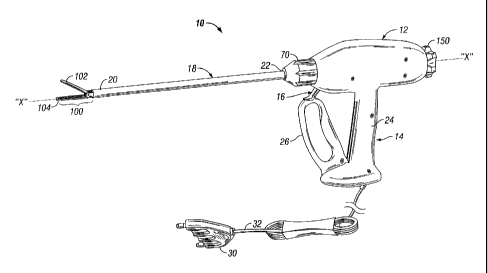
[0009] The locking mechanism may include a locking shaft extending
longitudinally through said shaft, wherein said locking shaft has a distal end
operatively associated with said second jaw member; and a locking pin
extending
transversely from said distal end of said locking shaft, wherein said locking
pin is
selectively engagable with each of said plurality of inter-engagement elements
of
3
CA 02814900 2013-05-01
said second jaw member. Accordingly, when said locking mechanism is in said
first position, said locking pin is engaged with said inter-engagement
elements of
said second jaw member. Additionally, when said locking mechanism is in the
second position, said locking pin is disengaged from said inter-engaging
elements of said second jaw member.
[0010] The actuation mechanism may include an actuation shaft
reciprocally and rotatably disposed in said locking shaft, wherein the
actuation
shaft includes a distal end and a proximal end. The actuation mechanism may
further include a band having a proximal end operatively connected to said
distal
end of said actuation shaft, and a distal end extending through an aperture
formed in said distal end of said locking shaft and operatively connected to
said
first jaw member. Accordingly, when said actuation shaft is displaced in one
of
an axially proximal and distal direction, said first jaw member is articulated
between said first orientation and said plurality of second orientations.
[0011] The instrument may further include an articulation knob operatively
associated with said locking mechanism and said actuation mechanism. The
articulation knob may effectuate independent operation of one of said locking
mechanism and said actuation mechanism. It is envisioned that axial
displacement of said articulation knob in one of a proximal and distal
direction
may manipulate said locking mechanism between said first and said second
positions. It is further envisioned that rotation of said articulation knob
may
4
CA 02814900 2013-05-01
manipulate said actuation mechanism to move said first jaw member between
said first orientation and said plurality of second orientations.
[0012] The locking mechanism may include a first collar operatively
connected to a proximal end of said locking shaft; a pair of diametrically
opposed
connecting rods extending proximally from said first collar; and a second
collar
operatively connected to said proximal end of at least one of said connecting
rods. The second collar may be rotatably supported on said articulation knob.
Accordingly, as said articulation knob is axially displaced in one of said
proximal
and distal directions, said connecting rods transmit the axial displacement of
said
articulation knob to said locking rod.
[0013] The actuation mechanism may further include a lead screw
operatively connected to a proximal end of said actuation shaft; and a drive
shaft
operatively interconnecting said lead screw and said articulation knob.
Accordingly, rotation of said articulation knob moves said drive shaft and
said
drive shaft transmits rotation to said lead screw. Additionally, said lead
screw
axially displaces said actuation shaft.
[0014] The electrosurgical instrument may further include an indexing
plate operatively associated with at least one of said connecting rods. The
indexing plate may be operatively engagable with said articulation knob. The
indexing plate defines a plurality of angular orientations for said second jaw
member.
CA 02814900 2013-05-01
[0015] The second jaw member may be biased to said axially aligned
orientation.
[0016] The end effector may further include a pivot pin extending through
said first and said second jaw members. The pivot pin is transversely oriented
with respect to the longitudinal axis and coplanar with respect to a plane
defined
by a tissue contacting surface of said second jaw member.
[0017] The band may be fabricated from a material capable of transmitting
compressive and tensile loads, such as, for example, spring steel.
[0018] The electrosurgical instrument may further include electrodes
disposed on said first and said second jaw members. The electrodes may be in
juxtaposed relation to one another when said first and said second jaw members
are substantially aligned.
[0019] The second jaw member may include a pair of spaced apart
flanges extending proximally therefrom, wherein each flange may be provided
with at least one inter-engaging element. The first jaw member may include a
knuckle extending proximally therefrom and may be disposed between said pair
of flanges. The band may be pivotably connected to said knuckle at a
predetermined location. For example, the predetermined location may be
spaced a transverse distance from said pivot pin in the longitudinal axis.
[0020] The handle assembly of the electrosurgical instrument may be a
reverse pivoting handle.
6
CA 02814900 2013-05-01
[0021] The electrosurgical instrument may further include a series of
linkages configured and adapted to urge said lead screw in a distal direction
and
drive said actuation shaft in said distal direction when said pivoting handle
is
squeezed.
[0022] The electrosurgical instrument may further include a biasing
member operatively associated with said pivoting handle for maintaining and
returning said pivoting handle to an un-actuated position.
[0023] It is envisioned that at least one of said first and second jaw
members includes a longitudinally extending knife blade.
[0024] According to another aspect of the present disclosure, a bipolar
electrosurgical instrument including an end effector is provided. The
instrument
includes a first pivotable jaw member; and a second pivotable jaw member
operatively associated with said first jaw member. The first and second jaw
members are movable between a first orientation in which said first and second
jaw members are axially aligned with a longitudinal axis of the instrument,
and at
least one second orientation in which said first and second jaw members are
angled with respect to the longitudinal axis of the instrument. Each jaw
member
includes an electrode operatively associated therewith and defines tissue
contacting surfaces in juxtaposed relation to one another. The first and
second
jaw members have an open condition in which said first and second jaw
members are relatively spaced from one another and a closed condition in which
said first and second jaw members are relatively close to one another
7
CA 02814900 2013-05-01
[0025] The instrument further includes a locking mechanism operatively
associated with said second jaw member. The locking mechanism has a first
position in which said locking mechanism engages said second jaw member and
prevents movement of said second jaw member, and a second position in which
said locking mechanism is disengaged from said second jaw member and allows
for movement of said second jaw member between said first orientation and said
at least one second orientation.
[0026] The instrument further includes an actuation mechanism operable
to move said first jaw member between said first orientation and said at least
one
second orientation.
[0027] The locking mechanism includes a locking shaft having a distal end
operatively associated with said second jaw member; and a locking pin
extending
transversely from said distal end of said locking shaft. The locking pin is
selectively engagable between a plurality of inter-engagement elements
provided
on said second jaw member. Accordingly, when said locking mechanism is in
said first position, said locking pin is engaged with one of said plurality
inter-
engagement elements of said second jaw member. Additionally, when said
locking mechanism is in said second position, said locking pin is disengaged
from said inter-engaging elements of said second jaw member.
[0028] The actuation mechanism may include an actuation shaft rotatably
disposed within said locking shaft, wherein said actuation shaft includes a
distal
end and a proximal end; and a band having a proximal end operatively
8
CA 02814900 2013-05-01
connected to said distal end of said actuation shaft, and a distal end
extending
through an aperture formed in said distal end of said locking shaft and
operatively connected to said first jaw member. Accordingly, when said
actuation
shaft is displaced in one of an axially proximal and distal direction, said
first jaw
member is articulated between said first orientation and said at least one
second
orientation.
[0029] The electrosurgical instrument may further include an articulation
knob operatively supported at a proximal end of the instrument. The
articulation
knob may be operatively associated with said locking mechanism and said
actuation mechanism. Accordingly, said articulation knob effectuates
independent operation of at least one of said locking mechanism and said
actuation mechanism. It is envisioned that axial displacement of said
articulation
knob results in movement of said locking mechanism between said first and
second positions. It is further envisioned that rotation of said articulation
knob
may move said actuation mechanism to move said first jaw member between
said first orientation and said at least one second orientation.
[0030] The locking mechanism may include a first collar operatively
connected to a proximal end of said locking shaft; a pair of diametrically
opposed
connecting rods extending proximally from said first collar; and a second
collar
operatively connected to at least one connecting rod. The second collar is
rotatably supported on said articulation knob, wherein as said articulation
knob is
9
CA 02814900 2013-05-01
axially displaced in one of said proximal and distal directions, said
connecting
rods transmit the axial displacement of said articulation knob to said locking
rod.
[0031] The actuation mechanism may further include a lead screw
operatively connected to a proximal end of said actuation shaft; and a drive
shaft
operatively interconnecting said lead screw and said articulation knob.
Accordingly, as said articulation knob is rotated, said drive shaft transmits
rotation to said lead screw and said lead screw converts rotation thereof into
the
axial displacement of said actuation shaft.
[0032] The eiectrosurgical instrument may further include an indexing
plate operatively supported between said pair of connecting rods and
operatively
engagable with said articulation knob. The indexing plate defines a plurality
of
angular orientations for said second jaw member.
[0033] The second jaw member may be biased to said axially aligned
orientation.
[0034] The end effector may include a pivot pin extending through said
first and second jaw members. The pivot pin may be transversely oriented with
respect to said longitudinal axis of the instrument and coplanar with respect
to a
plane defined by said tissue contacting surface of said second jaw member.
[0035] According to a further aspect of the present disclosure, a bipolar
electrosurgical instrument is provided. The instrument includes an end
effector
operatively associated with a distal end of a shaft. The end effector includes
a
CA 02814900 2013-05-01
first jaw member pivotably coupled to a distal end of said shaft; a second jaw
member pivotably coupled to said distal end of said shaft, wherein at least
one of
said first and said second jaw members comprise a plurality of inter-
engagement
elements; and a plurality of electrodes with at least one electrode being
operatively disposed on said first jaw member and at least another electrode
being operatively disposed on said second jaw member, wherein said electrodes
transmit radiofrequency energy therebetween. The first and second jaw
members move from a first orientation in which said first and said second jaw
member are axially aligned with a longitudinal axis of said shaft and a
plurality of
second orientations in which said first and said second jaw members are angled
with respect to the longitudinal axis. The first and second jaw members have
an
open condition in which said first and second jaws members are spaced from
one another and a closed condition in which said first and second jaw members
are substantially in close proximity to one another.
[0036] The instrument further includes a locking mechanism operatively
associated with the second jaw member to prevent movement of the second jaw
member between said first orientation and any of said plurality of second
orientations, and a second position in which said locking mechanism is
disengaged from said second jaw member and allows for movement of said
second jaw member between said first orientation and any of said plurality of
second orientations.
11
CA 02814900 2013-05-01
[0037] The instrument still further includes an actuation mechanism
operatively connected to at least one of said first jaw member and second jaw
member. The actuation mechanism is operable to move at least one of said first
jaw member and second jaw member between said first orientation and said
plurality of second orientations.
[0038] According to yet another aspect of the present disclosure, a
bipolar
electrosurgical instrument is provided. The instrument includes an end
effector
operatively associated with a distal end of a shaft. The end effector includes
a
first jaw member pivotably coupled to a distal end of said shaft; a second jaw
member pivotably coupled to said distal end of said shaft; and a plurality of
electrodes with at least one electrode being operatively disposed on said
first jaw
member and at least another electrode being operatively disposed on said
second jaw member, wherein said electrodes transmit radiofrequency energy
therebetween. The end effector defines a longitudinal axis with said shaft
when
said end effector is in a coaxial position. The end effector is articulatable
from an
angle of about 00 with respect to said longitudinal axis to an angle of about
60
with respect to said longitudinal axis. Additionally, the first and said
second jaw
members are adapted to move between an open position and a closed position
at any of a plurality of angular positions of said end effector.
[0039] The first and second jaw members may be openable and closable.
The end effector may articulate by a single linkage.
12
CA 02814900 2013-05-01
[0040] The electrosurgical instrument may further include a locking device
for locking said end effector at any of said plurality of angular positions.
[0041] The electrosurgical instrument may still further include a cutting
device. The cutting device may traverse through a channel in at least one said
first and said second jaw members.
[0042] The end effector may have a predetermined size to be introduced
and articulate in a pulmonary tissue region. The end effector with said
predetermined size may be configured to apply radiofrequency energy in said
pulmonary tissue region. The end effector with said predetermined size may
form a lung parenchyma seal in said pulmonary tissue region.
[0043] Other objects and features of the present disclosure will become
apparent from consideration of the following description taken in conjunction
with
the accompanying drawings.
BRIEF DESCRIPTION OF THE DRAWINGS
[0044] By way of example only, embodiments of the electrosurgical
instrument of the present disclosure will be described with reference to the
accompanying drawings, in which:
[0045] FIG. 1 is a perspective view of an articulating bipolar electro-
surgical instrument according to an embodiment of the present disclosure;
13
CA 02814900 2013-05-01
[0046] FIG. 2 is an enlarged, right side perspective view of a distal end
of
the surgical instrument of FIG. 1, including an end effector in accordance
with an
embodiment of the present disclosure, depicting a pair of opposed jaw members
thereof in an axially aligned orientation and in a closed condition;
[0047] FIG. 3 is an enlarged, front perspective view of the end effector
of
FIG. 2, depicting a first of the pair of opposed jaw members in the axially
aligned
orientation and a second of the pair of opposed jaw members in an angled or
open condition;
[0048] FIG. 4 is a left side perspective view of the end effector of FIGS.
2-
3, depicting the a first of the pair of opposed jaw members in the axially
aligned
orientation and a second of the pair of opposed jaw members in an angled or
open condition;
[0049] FIG. 5 is a left side perspective view of the end effector of FIGS.
2-
4, depicting the pair of opposed jaw members in an articulated orientation and
in
a closed condition;
[0050] FIG. 6 is a left side perspective view of the end effector of FIGS.
2-
5, with a portion of the outer tube broken away and/or removed in order to
illustrate the locking mechanism and the articulating mechanism of the present
disclosure;
14
CA 02814900 2013-05-01
[0051] FIG. 7 is a left side perspective view of the end effector of FIGS.
2-
6, with the outer tube and locking shaft entirely removed in order to further
illustrate the articulating mechanism of FIG. 6;
[0052] FIG. 8 is a perspective view of the locking mechanism and
articulating mechanism according to an embodiment of the present disclosure;
[0053] FIG. 9 is a rear perspective view of the locking mechanism and
articulating mechanism of FIG. 8;
[0054] FIG. 10 is an enlarged, right side perspective view of a distal end
of
a surgical instrument including an end effector, in accordance with an
alternate
embodiment of the present disclosure, showing a pair of opposed jaw members,
in an axially aligned orientation;
[0055] FIG. Ills an enlarged, right side, perspective view of the end
effector of FIG. 10, in an first articulated condition, showing an outer tube
shown
in phantom to illustrate the internal articulation joint;
[0056] FIG. 12 is an enlarged, right side perspective view of the end
effector of FIGS. 10 and 11, illustrating the jaw members in an open
condition;
[0057] FIG. 13 is an enlarged, right side perspective view of the end
effector of FIGS. 10-12, illustrating the jaw members in a closed condition;
CA 02814900 2013-05-01
[0058] FIG. 14 is an enlarged, front perspective view of the end effector
of
FIGS. 10-13 showing the jaw members in the axially aligned orientation and
with
the jaws in the open condition;
[0059] FIG. 15 is an enlarged, right side perspective view of the end
effector of FIGS. 10-14, in a second articulated orientation, with the outer
tube
shown in phantom;
[0060] FIG. 16 is an enlarged, top perspective view of the end effector of
FIGS. 10-15;
[0061] FIG. 17 is an enlarged, rear perspective view of the end effector
of
FIGS. 10-16, showing an axle holder shown in phantom;
[0062] FIG. 18 is an enlarged, front perspective view of the end effector
of
FIGS. 10-17, with the jaw members shown in phantom, illustrating a knife
carrier
according to the present disclosure;
[0063] FIG. 19 is an enlarged, transverse, schematic cross-sectional view
of an end effector according to another embodiment of the present disclosure,
as
taken through a pivot axis thereof;
[0064] FIG. 20 is an enlarged, transverse schematic cross-sectional view
of an end effector according to yet another embodiment of the present
disclosure, as taken through a pivot axis thereof;
16
CA 02814900 2013-05-01
[0065] FIG. 21 is an enlarged, right side perspective view of a distal end
of
the surgical instrument of FIG. 1, including an end effector, in accordance
with
yet another embodiment of the present disclosure, showing a pair of opposed
jaw
members, in an axially aligned orientation;
[0066] FIG. 22 is an enlarged, right side, perspective view of the end
effector of FIG. 21, in an first articulated condition, showing an outer tube
shown
in phantom to illustrate the internal articulation joint;
[0067] FIG. 23 is an enlarged, right side perspective view of the end
effector of FIGS. 21 and 22, illustrating the jaw members in an open
condition;
[0068] FIG. 24 is an enlarged, right side perspective view of the end
effector of FIGS. 21-23, illustrating the jaw members in a closed condition;
[0069] FIG. 25 is an enlarged, front perspective view of the end effector
of
FIGS. 21-24 showing the jaw members in the axially aligned orientation and
with
the jaws in the open condition;
[0070] FIG. 26 is an enlarged, right side perspective view of the end
effector of FIGS. 21-25, in a second articulated condition, with the outer
tube
shown in phantom;
[0071] FIG. 27 is an enlarged, top perspective view of the end effector of
FIGS. 21-26;
17
CA 02814900 2013-05-01
. ,
[0072] FIG. 28 is an enlarged, rear perspective view of the end effector
of
FIGS. 21-27, showing an axle holder shown in phantom;
[0073] FIG. 29 is an enlarged, front perspective view of the end effector
of
FIGS. 21-28, with the jaw members shown in phantom, illustrating a knife
carrier
according to the present disclosure;
[0074] FIG. 30 is an enlarged, transverse, schematic cross-sectional view
of an end effector according to another embodiment of the present disclosure,
as
taken through a pivot axis thereof; and
[0075] FIG. 311s an enlarged, transverse schematic cross-sectional view
of an end effector according to yet another embodiment of the present
disclosure, as taken through a pivot axis thereof.
DETAILED DESCRIPTION
[0076] Detailed embodiments of the presently disclosed instruments,
devices and systems will now be described in detail with reference to the
drawing
figures wherein like reference numerals identify similar or identical
elements. In
the drawings and in the description which follows, the term "proximal", as is
traditional, will refer to the end of the instrument, device and/or system
which is
closest to the operator while the term "distal" will refer to the end of the
instrument, device and/or system which is furthest from the operator.
18
CA 02814900 2013-05-01
[0077] Referring to FIG. 1, a bipolar electro-surgical instrument,
according
to an embodiment of the present disclosure, is shown generally as 10. Electro-
surgical instrument 10 generally includes a housing 12, a handle assembly 14,
an activation assembly 16, and an end effector 100, in accordance with the
present disclosure, which operates to grasp, seal and/or cut tissue.
[0078] More particularly, instrument 10 includes a shaft 18, defining a
longitudinal "X" axis, which has a distal end 20 dimensioned to mechanically
engage end effector 100 and a proximal end 22 which mechanically engages
housing 12. Instrument 10 also includes an electrical interface or plug 30
which
connects instrument 10 to a source of electrosurgical energy, e.g., an
electrosurgical generator (not shown). An electrical cable 32 extends from
plug
30 and is securely connected to housing 12 of instrument 10. Cable 32 is
internally divided within housing 12 to transmit electrosurgical energy
through
various electrical feed paths (not shown) to end effector 100. Handle assembly
14 includes a fixed handle 24 and a movable handle, e.g., a reverse pivot
handle
26. Fixed handle 24 is integrally associated with housing 12 and movable
handle
26 is displaceable relative to fixed handle 24 to actuate a pair of opposing
jaw
members 102 and 104 of end effector 100.
[0079] A collar 70 is operatively mounted to the proximal portion of
housing 12 in a manner such that rotation of collar 70 will cause
corresponding
rotation of shaft 18 to increase the range of operability of surgical
instrument 10.
19
CA 02814900 2013-05-01
[0080] Turning now to FIGS. 2-7, an end effector in accordance with an
embodiment of the present disclosure is generally designated as 100. As
briefly
mentioned above, end effector 100 includes a first or upper jaw member 102 and
a second or lower jaw member 104 pivotably associated with one another and
pivotably associated with distal end 20 of shaft 18. Each jaw member 102, 104
has a respective electrode 106, 108 in juxtaposed relation to one another.
Each
electrode 106, 108 defines a respective tissue contacting surface 106a, 108a
(see FIG. 3).
[0081] As best seen in FIGS. 6 and 7, the proximal end of second jaw
member 104 includes a yoke 110 defined by a pair of opposed, spaced apart
flanges 112, 114 which extend therefrom. Preferably, flanges 112, 114 are at
least substantially orthogonally oriented with respect to a plane defined by
tissue
contacting surface 108a and at least substantially parallel to the
longitudinal "X"
axis of shaft 18. Each flange 112, 114 defines an arcuate edge including at
least
one, preferably a plurality of, inter-engaging element(s) 116, such as, for
example, gears, teeth, or the like.
[0082] First jaw member 102 includes a knuckle 118 extending from a
proximal end thereof. Knuckle 118 is configured and dimensioned to be
positionable between flanges 112, 114. First jaw member 102 and second jaw
member 104 are pivotably connected to one another by a pivot pin 120 extending
through flanges 112, 114 and knuckle 118. Pivot pin 120 defines a pivot axis
"Z"
(see FIG. 3) which is oriented in a direction at least substantially
orthogonal to
CA 02814900 2013-05-01
the longitudinal "X" axis of shaft 18 and is in a plane which is at least
substantially parallel to the plane defined by tissue contacting surface 108a.
Preferably, pivot pin 120 extends through the longitudinal "X" axis of shaft
18.
[0083] Preferably, second jaw member 104 is biased to an angled
orientation with respect to the longitudinal "X" axis, as seen in FIG. 5, by a
biasing member (not shown), such as, for example, a spring. The biasing
member tends to maintain second jaw member 104 angled with respect to the
central longitudinal "X" axis.
[0084] Preferably, instrument 10 is provided with a locking mechanism 140
for maintaining second jaw member 104 in an axially aligned orientation or in
any
number of angled orientations with respect to the longitudinal "X" axis.
Preferably, the angled orientations include orientations up to a 90
orientation
with respect to the longitudinal "X" axis and, more preferably, orientations
up to a
60 orientation with respect to the longitudinal "X" axis. As seen in FIGS. 6
and
8, locking mechanism 140 includes an articulation locking shaft 142 having a
distal end 142a, and a locking pin 144 extending from distal end 142a of
locking
shaft 142, preferably, diametrically from either side of distal end 142a of
locking
shaft 142. Preferably, locking shaft 142 is sized and positioned to be
disposed
between flanges 112, 114 of second jaw member 104 and locking pin 144
extends from either side of distal end 142a of locking shaft 142 an amount
sufficient to selectively engage inter-engaging element(s) 116 of flanges 112,
114.
21
CA 02814900 2013-05-01
[0085] Locking mechanism 140 has a first position in which locking shaft
142 is in a distally advanced position such that locking pin 144 engages inter-
engaging element(s) 116 of flanges 112, 114 and thereby prevents articulation
(e.g., pivoting, angular displacement or rotational displacement) of second
jaw
member 104 with respect to the central longitudinal "X" axis, and at least one
second position in which locking shaft 142 is proximally spaced from the first
distally advanced position such that locking pin 144 is disengaged from inter-
engaging element(s) 116 of flanges 112, 114 and thereby permits articulation
(e.g., pivoting, angular displacement or rotational displacement) of second
jaw
member 104, about pivot pin 120, with respect to the central longitudinal "X"
axis
to any number of angled or articulated orientations.
[0086] As seen in FIG. 8, a proximal end 142b of locking shaft 142 is
rotatably coupled to and/or otherwise journaled in a first or distal collar
146a. A
pair of connecting rods 148 interconnect first collar 146a with a second or
proximal collar 146b (see FIGS. 8 and 9). Preferably, connecting rods 148
extend along either side of an actuation mechanism and/or linkage 160. Second
collar 146b is rotatably coupled to and/or otherwise journaled in an annular
channel formed in an articulation knob 150.
[0087] The articulation knob 150 is operatively supported on a proximal
end of housing 12. Articulation knob 150 defines a central axis of rotation
which
is preferably axially aligned with the longitudinal "X" axis.
22
CA 02814900 2013-05-01
[0088] Turning now to FIGS. 6-9, instrument 10 is further provided with an
actuation mechanism 160 to effectuate articulation (e.g., angular movement
and/or rotation) of first jaw member 102 about pivot pin 120. Actuation
mechanism 160 includes an actuation shaft 162 reciprocatingly received in
locking shaft 142 of locking mechanism 140 (Fig. 6). Actuation shaft 162
includes a distal end 162a operatively connected to knuckle 118 of first jaw
member 102, and a proximal end 162b operatively connected to a lead screw
154 of actuation mechanism 160 (Fig. 8). Actuation mechanism further includes
a drive shaft 152 inter-connecting articulation knob 150 and lead screw 154.
[0089] In particular, actuation mechanism 160 includes a linkage 164
having a distal end 164a, extending through an aperture 142c formed in distal
end 142a of locking shaft 142 and pivotably connected to knuckle 118 of first
jaw
member 102 by a pivot pin 166, and a proximal end 164b, pivotably connected to
distal end 162a of actuation shaft 162. Preferably, pivot pin 166 is spaced a
transverse distance from pivot pin 120. Linkage 164 has an angled shape for
increased leverage.
[0090] In operation, as seen in FIGS. 6-9 and as will be described in
greater detail below, articulation knob 150 performs two functions: the first
function being the articulation of first jaw member 102 and second jaw member
104, between an axially aligned orientation and a plurality of angled
orientations;
and the second function being the locking of second jaw member 104 in the
axially aligned orientation or any of the plurality of angled orientations.
23
CA 02814900 2013-05-01
[0091] The first function of articulation knob 150 is performed as a
result of
rotation of articulation knob 150. As articulation knob 150 is rotated in the
direction of arrow "A" (see FIG. 8), articulation knob 150 rotates drive shaft
152
which, in turn, rotates lead screw 154. As lead screw 154 is rotated in the
direction of arrow "A", lead screw 154 is displaced in a proximal direction,
extending the distance between pivot 166 and cam 168. Lead screw 154 also
desirably lengthens shaft 162 so that the force applied to the compression
spring
176 during activation remains consistent. As discussed below, predetermined
pressure applied to the tissue optimizes tissue sealing. As actuation shaft
162 is
displaced in an axially proximal direction, first jaw member 102 is
articulated
and/or pivoted about pivot pin 120 between an orientation in which first jaw
member 102 is at least substantially axially aligned with the longitudinal "X"
axis
(see FIG. 2), and a plurality of orientations in which first jaw member 102 is
angled with respect to the longitudinal "X" axis (see FIGS. 3-7).
[0092] With pin 144 engaged in engaging elements 116, the pivoting of
first jaw member 102 occurs separately from second jaw member 104, which
remains stationary. With pin 144 disengaged from engaging elements 116, the
pivoting of first jaw member 102 and second jaw member 104 occurs jointly, as
the second jaw member 104 is connected to the first jaw member 102 through
the biasing member. The degree to which first jaw member 102 and second jaw
member 104 is angled is dependent upon the amount that articulation knob 150
is rotated.
24
CA 02814900 2013-05-01
[0093] The second function of articulation knob 150 is performed as a
result of axial displacement of articulation knob 150 in the direction of, and
opposite to the direction of, arrow "B". As articulation knob 150 is displaced
in
the direction of arrow "B" (i.e., in a proximal direction), articulation knob
150 pulls
on connecting rods 148 which, in turn, pull on locking shaft 142. As locking
shaft
142 is displaced in the direction of arrow "6", locking pin 144 is
disassociated
and/or otherwise disengaged from inter-engagement element(s) 116. In so
doing, the biasing member (not shown) is free to urge second jaw member 104
about pivot pin 120, from an axially aligned orientation (see FIGS. 2-4, 6 and
7)
to an angled and/or articulated orientation (see FIG. 5) as first jaw member
102 is
articulated by rotation of articulation knob 150.
[0094] Once second jaw member 104 has been angled and/or articulated,
articulation knob 150 is displaced in a direction opposite to arrow "B" (e.g.,
driven
forward) in order to drive locking shaft 142 in a distal direction and re-
engage
locking pin 144 with inter-engagement element(s) 116 of flanges 112, 114. In
so
doing, second jaw member 104 is fixed in the needed and/or desired angle "e"
(see FIG. 5), and jaw member 102 may be pivoted separately.
[0095] Actuation shaft 162 is also axially displaced as a result of the
manipulation of reverse pivot handle 26 (Fig. 8) and subsequent manipulation
of
actuation mechanism 160. In particular, as pivot handle 26 is squeezed,
linkages
168a-168e (see FIG. 8) of actuation mechanism 160 are manipulated in such a
CA 02814900 2013-05-01
manner so as to drive actuation shaft 162 in the proximal direction to pivot
first
jaw member 102 about pivot pin 120.
[0096] Desirably, a cam plate 174 is provided which is urged in a proximal
direction, against the force of a biasing member 176 (e.g., a tensile loading
spring), as pivot handle 26 is squeezed. In this manner, when pivot handle 26
is
released, cam plate 174 is urged in a distal direction by biasing member 176
thereby urging actuation shaft 162 distally and, in turn, opening end effector
100
(e.g., spacing first jaw member 102 from second jaw member 104). Additionally,
biasing member 176 tends to return and/or maintain pivot handle 26 in an un-
squeezed and/or un-actuated condition.
[0097] As seen in FIGS. 8 and 9, instrument 10 may be provided with an
indexing plate 170 operatively associated with articulation knob 150. Indexing
plate 170 includes a plurality of openings 172 formed at particular and/or
discrete
locations therein. Openings 172 are configured and dimensioned to selectively
receive a pin 156 (see FIG. 9) extending distally from articulation knob 150.
In
use, as articulation knob 150 is rotated, pin 156, extending from articulation
knob
150, selectively engages openings 172 of indexing plate 170 in order to define
predetermined angular orientations for first jaw member 102. Preferably,
openings 172 of indexing plate 170 are "clocked" (i.e., correspond with) the
position of inter-engagement element(s) 116 of Ranges 112, 114. In use, pin
156
is disengaged from openings 172 by pulling articulation knob 150 in a proximal
direction.
26
CA 02814900 2013-05-01
[0098] Indexing plate 170 preferably includes a pair of recesses 178 (see
FIG. 9) formed therein for receipt and slidable engagement with rods 148.
Recesses 178 and rods 148 inter-engage with one another to thereby prevent
rotation of indexing plate 170 about the longitudinal "X" axis and maintain
the
relative position of openings 172 with respect to articulation knob 150. In
this
manner, the discrete angular positions of second jaw member 104, for each
position of opening 172, is maintained.
[0099] With reference to FIGS. 1-9, use and operation of instrument 10
will
now be described in greater detail. Initially, with first and second jaw
members
102, 104 of end effector 100 in a substantially axially aligned condition, end
effector 100 of surgical instrument 10 is introduced into an operative site,
e.g.,
the thoracic cavity, through a port or the like (not shown).
[00100] Once introduced into the operative site, and in the open jaw
configuration, as briefly described above, articulation knob 150 is rotated in
the
direction of arrow "A" (see FIG. 8) to pivot and/or articulate first jaw
member 102
about pivot pin 120. As articulation knob 150 is rotated in the direction of
arrow
"A", drive shaft 152 rotates lead screw 154 and, in turn, moves actuation
shaft
162, in the direction opposite of arrow "B" (i.e., in a distal direction). As
actuation
shaft 162 is displaced in a distal direction, first jaw member 102 and second
jaw
member 104 are pivoted about pivot pin 120 to a desired and/or needed angled
and/or articulated orientation. Aligning articulation knob 150 with indexing
27
CA 02814900 2013-05-01
positions on indexing plate 170 will allow connecting rods 148 and locking
shaft
142 to move distally and place pin 144 in recess 116.
[00101] With end effector 100 in the open condition, instrument 10 may be
manipulated to place end effector 100 about the tissue to be treated, i.e., to
place
first and second jaw member 102, 104 on either side of the tissue to be
treated.
With end effector so positioned, articulation knob 150 is displaced in the
direction
of arrow "B", i.e., withdrawn in a proximal direction, to permit rotation
and/or
articulation of second jaw member 104, under the influence of the biasing
member (not shown), about pivot pin 120. In particular, as articulation knob
150
is drawn in the proximal direction, connecting rods 148 and, in turn, locking
shaft
142 are displaced in a proximal direction until locking pin 144 is
disassociated
and/or otherwise disengaged from inter-engagement element(s) 116 of second
jaw member 104.
[00102] Preferably, instrument 10 is configured and dimensioned to permit
pivoting of first jaw member 102 and, in turn, second jaw member 104, to an
angle "0" (see FIG. 5) of from at least about 0 to at least about 60 ,
relative to
the longitudinal "X" axis. For example, pulling on knob 150 releases second
jaw
member 104, which is free to rotate away from an axially-aligned position.
Most
preferably, indexing plate 170 is configured to inter-engage with articulation
knob
150 such that first jaw member 102 and, in turn, second jaw member 104, are
articulated in predetermined increments; for example, 100 increments may be
used.
28
CA 02814900 2013-05-01
[00103] If needed and/or desired, end effector 100 may be rotated about
the longitudinal "X" axis by rotating collar 70 (see FIG. 1) about the
longitudinal
"X" axis. In so doing, the user does not have to rotate the entirety of
instrument
10, including housing 12, about the longitudinal "X" axis.
[00104] Closing and clamping of end effector 100 is accomplished by
squeezing handle 26. In particular, as seen in FIGS. 7 and 8, as handle 26 is
squeezed linkages 168a-168e of actuation mechanism 160 are manipulated in
such a manner so as to move actuation shaft 162 in a proximal direction.
Movement of actuation shaft 162 in a proximal direction results in pivoting of
first
jaw member 102 about pivot pin 120, thereby at least substantially
approximating
tissue contacting surface 106a of first jaw member 102 toward tissue
contacting
surface 108a of second jaw member 104.
[00105] With end effector 100 clamped onto the tissue to be treated, RF
energy may then be transmitted to electrodes 106, 108 of first and second jaw
members 102, 104, respectively, to seal or fuse the tissue to be treated. By
way
of example only, the RF energy may be activated by squeezing activation
assembly 16 (see FIG. 1). Following sealing of the tissue to be treated, the
handle member is moved forward to re-open end effector 100 and/or otherwise
space first jaw member 102 from second jaw member 104 and thereby release
the treated tissue therefrom. The process may be repeated as many times as
necessary depending on the particular surgical procedure and/or depending on a
particular surgical purpose.
29
CA 02814900 2013-05-01
[00106] Alternatively, following the surgical procedure and/or when
desired,
first and second jaw members 102, 104 are returned to the axially aligned
orientation in order to withdraw surgical instrument 10 and, in turn, end
effector
100, from the operative site. Instrument 10 is manipulated to space end
effector
100 from the treated tissue, i.e., to position end effector 100 such that
first and
second jaw members 102, 104 are free to rotate and are not obstructed by other
tissue and/or body organs.
[00107] With end effector 100 so positioned, articulation knob 150 is
displaced in the proximal direction, i.e., in the direction of arrow "B", to
once
again free second jaw member 104 to rotate about pivot pin 120. Then,
articulation knob 150 is rotated in a direction opposite to arrow "A" in order
to
pivot first jaw member. 102 from the angled and/or articulated orientation to
the
axially aligned orientation. In so doing, first jaw member 102 engages second
jaw member 104 and causes second jaw member 104 to be pivoted from the
angled orientation to the axially aligned orientation. Once first and second
jaw
members 102, 104 are returned to the axially aligned orientation, instrument
10
and, in turn, end effector 100, may be withdrawn from the operative site,
[00108] It is envisioned that one of the first and second jaw members 102,
104, preferably second jaw member 104, is provided with a reciprocating knife
assembly (not shown), operatively associated therewith. As best seen in FIGS.
3, 4 and 7, second jaw member 104 defines a longitudinally oriented knife
track
172a formed in tissue contacting surface 108a of electrode 108, which
preferably
CA 02814900 2013-05-01
extends proximally beyond tissue contacting surface 108a of second jaw member
104.
[00109] The knife assembly may include a carrier slidably disposed within
second jaw member 104. The carrier is preferably fabricated from a flexible,
pliable and/or resilient material such that the carrier may flex and/or bend
with
the articulation of first and second jaw members 102, 104. The knife assembly
preferably further includes a knife blade extending from the carrier and
through
knife track 172a. For example, carrier 274 and knife blade 280 discussed below
in connection with FIG. 18 may be used in the instrument discussed above.
[00110] Preferably, first jaw member 102 is also provided with a
longitudinally oriented knife track (not shown) formed in tissue contacting
surface
106a of electrode 106. The knife track of first jaw member 102 is desirably
disposed in vertical registration with knife track 172a of second jaw member
104
when first jaw member 102 and second jaw member 104 are in close
approximation with one another. In this manner, the knife blade is also at
least
partially received and/or disposed in the knife track of first jaw member 102
when
first and second jaw members 102, 104 are approximated toward one another.
In addition, as the carrier of the knife assembly is displaced along second
jaw
member 104, the knife blade is also displaced through knife track 172a and
through the knife track of the first jaw member.
[00111] Preferably, in operation, following the clamping of the tissue to
be
treated between first and second jaw members 102, 104 and, preferably
31
CA 02814900 2013-05-01
following the application of RF energy to the tissue to be treated, the knife
assembly is actuated in a manner to drive the carrier and, in turn, the knife
blade,
in a distal direction, along the entire length of knife track 172a or at least
until the
knife blade traverses the width of the effected tissue. In so doing, the
treated
tissue is severed and/or otherwise cut in half. Following cutting of the
treated
tissue, the knife assembly is actuated to draw the carrier and, in turn, the
knife
blade, in a proximal direction, preferably to a proximal-most position. It is
envisioned that a biasing member (not shown) may be employed to automatically
bias the knife in a proximal-most position.
[00112] In further embodiments, carrier member 578 and cable loop 574, as
discussed below in connection with FIGS. 30 and 31, are used in the instrument
discussed above.
[00113] Desirably, use of the knife assembly to sever, divide, cut and/or
otherwise separate the tissue, following the application of RF energy, is left
to the
discretion of the surgeon.
[00114] Turning now to FIGS. 10-18, an end effector in accordance with an
alternate embodiment of the present disclosure is generally designated as 200.
End effector 200 is similar to end effector 100 and will only be discussed in
detail
to the extent necessary to identify differences in construction and operation.
End
effector 200 includes a first or upper jaw member 202 and a second or lower
jaw
member 204 pivotably associated with one another and pivotably associated with
distal end 20 of shaft 18. Each jaw member 202, 204 has a respective electrode
32
CA 02814900 2013-05-01
206, 208 in juxtaposed relation to one another. Each electrode 206, 208
defines
a respective tissue contacting surface 206a, 208a (see FIGS. 12, 14 and 15).
[00115] As seen in FIGS. 11-13, the proximal end of second jaw member
204 includes a yoke 210 defined by a pair of opposed, spaced apart flanges
212,
214 which extend therefrom. Preferably, flanges 212, 214 are at least
substantially orthogonally oriented with respect to a plane defined by tissue
contacting surface 208a and at least substantially parallel to longitudinal
axis "X"
of shaft 18. Each flange 212, 214 defines an arcuate edge including at least
one,
preferably a plurality of, engaging element(s) 216, such as, for example,
gears or
teeth and the like.
[00116] First jaw member 202 includes a knuckle 218 extending from a
proximal end thereof. Knuckle 218 is configured and dimensioned to be
positionable between flanges 212, 214. First jaw member 202 and second jaw
member 204 are pivotably connected to one another by a pivot pin 220 extending
through flanges 212, 214 and knuckle 218. Pivot pin 220 defines a pivot axis
"Z"
which is oriented in a direction at least substantially orthogonal to
longitudinal
axis "X" of shaft 18 and is in a plane which is at least substantially
parallel to the
plane defined by tissue contacting surface 208a. Preferably, pivot pin 220
extends across longitudinal axis "X" of shaft 18.
[00117] As best seen in FIGS. 11-13 and 15-18, an articulation rack 230 is
provided which extends through and is slidably associated with shaft 18 of
instrument 10. Articulation rack 230 is desirably operatively associated with
teeth
33
CA 02814900 2013-05-01
216 of second jaw member 204. Preferably, articulation rack 230 includes a
pair
of spaced apart fingers 232a, 232b extending distally therefrom. As will be
described in greater detail below, fingers 232a, 232b are spaced apart an
amount sufficient to allow a knife assembly 270 to be selectively reciprocated
therebetween.
[00118] Each finger
232a, 232b includes at least one, preferably a plurality
of, inter-engaging members 234, e.g., gears or teeth, formed thereon. Teeth
234
of articulation rack 230 are configured and dimensioned to inter-engage with
and/or complement engaging elements 216 of flanges 212, 214 of second jaw
member 204. In this manner, and as will be described in greater detail below,
as
articulation rack 230 is selectively actuated in a distal direction relative
to shaft
18, second jaw member 204, and, in turn, first jaw member 202, is pivoted
about
the "Z" axis (i.e., about pivot pin 220) from at least an axially-aligned
position to
any number of articulated and/or angular positions. Likewise, as articulation
rack
230 is selectively actuated in a proximal direction relative to shaft 18,
second jaw
member 204, and, in turn, first jaw member 202, is pivoted about the "Z" axis
from the articulated and/or angular position toward a more axially-aligned
position. Stated differently, fingers 232a, 232b of articulation rack 230 act
as the
rack of a rack and pinion type linkage while flanges 212, 214 of second jaw
member 204 act as the pinion of the rack and pinion type linkage. Rack 230 is
connected to an articulation control knob (not shown), which has gears in
34
CA 02814900 2013-05-01
engagement with teeth on the proximal end of rack 230, so that turning of the
knob axially translates the rack, pivoting the second jaw member 204.
[00119] As seen in FIGS. 12, 13 and 15-18, end effector 200 further
includes a jaw actuation assembly 240 configured and adapted to permit
selective movement of the first jaw member 202 relative to second jaw member
204. More particularly, actuation assembly 240 includes a resilient band 242
which extends at least substantially axially through shaft 18 and a guide 244
(see
FIG. 17) which facilitates actuation of band 242. Actuation assembly 240
further
includes a holder assembly 246 including a pair of spaced-apart flanges 246a,
246b. Preferably, guide 244 is rotatingly supported by flanges 246a, 246b. A
supporting surface 244a of guide 244 is preferably spaced a distance "D" from
the central longitudinal "X" axis of shaft 18. (see FIG. 17) The size of
distance
"D" determines the degree first jaw member 202 pivots relative to second jaw
member 204. For example, the smaller distance "D" is, the smaller the degree
of
pivot of first jaw member 202 relative to second jaw member 204. Likewise, the
greater distance "D" is, the greater the degree of pivot of second jaw member
204.
[00120] Band 242 is reciprocatingly-disposed between flanges 246a, 246b
of holder assembly 246. As seen in FIG. 17, band 242 includes a "gooseneck-
like" distal end portion 248 having a distal end 248a fixedly secured to
knuckle
218 of first jaw member 202 and a proximal end 248b extending over guide 244.
CA 02814900 2013-05-01
The proximal end 248b is connected to a movable handle (not shown) for
actuating band 242 and jaws 202, 204.
[00121] in this manner, as will be described in greater detail below, as
band
242 is selectively displaced and/or advanced in a distal direction, first jaw
member 202 is pivoted about the "Z" axis (and about pivot pin 220) to space
first
jaw member 202 from second jaw member 204 for manipulating. Additionally, as
band 242 is selectively displaced in a proximal direction, first jaw member
202 is
pivoted about the "Z" axis and pivot pin 220 to approximate first jaw member
202
toward second jaw member 204 for grasping tissue.
[00122] Resilient band 242 is fabricated from a material which is
sufficiently
pliable to be conformable to a number of arcuate and/or wave-like
configurations
and which is sufficiently strong enough to withstand the various axial forces
associated with repeatedly grasping and manipulating tissue. Preferably,
resilient band 242 is fabricated from spring steel or the like.
[00123] End effector 200 is pivotably supported between tubular extensions
250a, 250b defined at the distal end of an outer tube 250 of shaft 18. Pivot
pin
220 is operatively engaged with tubular extensions 250a, 250b. Preferably, the
ends of pivot pin 220 extend through and are supported by tubular extensions
250a, 250b. Tubular extensions 250a, 250b are preferably configured and
dimensioned to enable end effector 200 to be pivoted from about 00 to at least
about 60 relative to longitudinal axis "X" of shaft 18.
36
CA 02814900 2013-05-01
[00124] With reference to FIGS. 10-18, the present disclosure also relates
a
method of sealing or fusing tissue. Initially, with first and second jaw
members
202, 204 of end effector 200 in a substantially axially aligned orientation or
condition, end effector 200 of surgical instrument 10 may be introduced into
an
operative site, e.g., the thoracic cavity, through a port or the like (not
shown).
[00125] Once introduced into the operative site, articulation rack 230 is
actuated and/or displaced in a distal direction, as indicated by arrow "A" of
FIG.
11, relative to outer tube 250. In so doing, teeth 234 of articulation rack
230
inter-engage with teeth 216 of flanges 212, 214 of second jaw member 204. As
such, first and second jaw members 202, 204 are manipulated and/or rotated
from the axially aligned orientation (i.e., a first position or condition) to
an
articulated, angular or inclined orientation (i.e., second position or
condition) in
which first and second jaws 202, 204 are inclined at a desired and/or
necessary
angle relative to longitudinal axis "X" of shaft 18.
[00126] It is envisioned that first and second jaw members 202, 204 may be
displaced in about 10 angular increments. This may be accomplished with a
ratchet-like mechanism (not shown). For example, a resilient pawl may be
arranged in outer tube 250 for allowing the jaws 202, 204 to articulate while
preventing movement in an opposite direction. The resilient pawl is desirably
releasable so the jaw members can resume an axially-aligned position. The pawl
may be actuated at the handle using any known means. In a further example, a
mechanism or the like may be used to prevent movement after articulating the
37
CA 02814900 2013-05-01
jaws to the desired position. The ratchet-like mechanism may be configured and
adapted to provide sensory feedback relating to the position of end effector
200.
For example, the ratchet-like mechanism may produce a "clicking" sound or
other
tactile or visual feedback for each 100 angular incremental displacement of
end
effector 200.
[00127] As jaw members 202 and 204 are pivoted about the "Z" axis and
pivot pin 220, band 242 flexes and/or bends accordingly. With first and second
jaw members 202, 204 in the open condition, band 242 is advanced in a distal
direction, as indicated by arrow "A" of FIG. 17, to further rotate first jaw
member
202, about the "Z" axis, relative to second jaw member 204 to thereby open end
effector 200. In one embodiment, band 242 may be formed from any flexible
and/or resilient material including metals or polymers, and laminates of metal
layers, such as steel. Another possible material is a laminate of polymer and
steel layers. Laminate materials allow the band to wrap around sharp radii.
[00128] With end effector 200 in the open condition, end effector 200 may
be positioned within the operative site in such a manner so as to position
first and
second jaw members 202, 204 on opposite sides of the tissue to be treated.
With end effector 200 so positioned, band 242 may be selectively drawn in a
proximal direction (i.e., opposite to the direction indicated by arrow "A") in
order
to approximate first jaw member 202 toward second jaw member 204 and close
end effector 200 about the tissue to be treated.
38
CA 02814900 2013-05-01
[00129] RF energy may then be transmitted to electrodes 206, 208 of the
first and second jaw members 202, 204, respectively, to seal or fuse, the
tissue.
Following sealing, band 242 is again selectively driven in a distal direction
to
open and/or otherwise space first jaw member 202 from second jaw member 204
to release the tissue. If desired and/or necessary, the process may be
repeated
for new un-treated tissue. The process may be repeated as many times as
necessary depending upon a particular surgical purpose.
[00130] Alternatively, when desired and/or when the surgical procedure is
completed, first and second jaw members 202, 204 may be returned to the
axially aligned orientation by withdrawing articulation rack 230 in a
direction
opposite to the direction indicated by arrow "A". With first and second jaw
members 202, 204 in the axially aligned orientation, end effector 200 may be
withdrawn from the operative cavity.
[00131] Electrosurgical tissue fusion of lung parenchyma typically produces
a seal quality which reduces the tendency of air leaks and the like, as
compared
to conventional surgical stapling apparatuses.
[00132] With particular reference to FIG. 18, one of first and second jaw
members 202, 204, preferably second jaw member 204, is provided with a
reciprocating knife assembly 270 operatively associated therewith. As seen in
FIGS. 12 and 14-16, second jaw member 204 defines a longitudinally oriented
knife track 272a formed in tissue contacting surface 208a of electrode 208,
which
39
CA 02814900 2013-05-01
extends proximally beyond tissue contacting surface 208a of second jaw member
204.
[00133] Knife assembly 270 includes a carrier 274 slidably disposed
between fingers 232a, 232b of articulation rack 230. Carrier 274 is preferably
fabricated from a flexible, pliable and/or resilient material such that
carrier 274
may flex and/or bend with the articulation of first and second jaw members
202,
204. The carrier 274 is connected to a cutter actuation control, such as a
button,
knob, slider actuator or handle at the proximal end of the instrument. Carrier
274
has a perpendicular portion that is bent or otherwise formed on carrier 274
and
blade 280 is welded or adhered to the perpendicular portion. Carrier 274 is
preferably formed from spring metal, although polymers or other metals may be
used. Knife assembly 270 further includes a knife blade 280 extending from
carrier 274 and through knife track 272a.
[00134] Preferably, the first jaw member 202 is also provided with a
longitudinally oriented knife track (not shown) formed in tissue contacting
surface
206a of electrode 206. The knife track of first jaw member 202 is preferably
disposed in vertical registration with knife track 272a of second jaw member
204
when first jaw member 202 and second jaw member 204 are in a closed
orientation. In this manner, knife blade 280 is also at least partially
received
and/or disposed in the knife track of first jaw member 202. In addition, as
carrier
274 is displaced along second jaw member 204, knife blade 280 is displaced
through knife track 272a and through the knife track of first jaw member 202.
CA 02814900 2013-05-01
[00135] In operation and with carrier 274 in a proximal-most position in
the
proximal-most end of knife track 272a, first and second jaw members 202, 204
may be selectively opened and closed about tissue, as described above.
Subsequent to the application of RF energy, carrier 274 may be actuated and/or
driven in a distal direction thereby driving knife blade 280 through knife
track
272a of second jaw member 204 and the knife track of first jaw member 202 in
order to sever the effected tissue. Knife carrier 274 may also be actuated to
cut
tissue prior to electrosurgical activation depending upon a particular
purpose.
[00136] Preferably, carrier 274 is driven in a distal direction until knife
blade
280 traverses the entire length of knife track 272a or at least until knife
blade 280
traverses the width of the effected tissue. Following the actuation of carrier
274
along knife track 272a (and the knife track of first jaw member 202), knife
blade
280 may be returned to the proximal-most position by withdrawing carrier 274
in
the proximal direction. A spring (or the like) may be employed to
automatically
bias the knife in the proximal-most position.
[00137] Use of knife assembly 270 to sever, divide and/or otherwise
separate the tissue, following the application of RF energy, is left to the
discretion
of the surgeon.
[00138] Turning now to FIG. 19, which shows a schematic, transverse
cross-sectional view of an alternative embodiment of an end effector 300,
taken
through the "Z" axis. As seen in FIG. 19, first and second jaw members 302,
304, respectively, are pivotable about a common pivot axis identified as axis
"Z".
41
CA 02814900 2013-05-01
A first jaw rack 312 is provided including a pair of spaced apart inter-
engaging
elements, e.g., gears or teeth, 316 for engaging complementary inter-engaging
elements, e.g., gears or teeth, 306 provided on first jaw member 302. In this
manner, as first jaw rack 312 is displaced in an axial direction relative to
first jaw
member 302, first jaw member 302 is pivoted about the "Z" axis. A second jaw
rack 314 is provided which includes a pair of spaced apart inter-engaging
elements, e.g., gear or teeth, 318 for engaging complementary inter-engaging
elements, e.g., gear or teeth, 308 provided on second jaw member 304. in this
manner, as second jaw rack 314 is displaced in an axial direction relative to
second jaw member 304, second jaw member 304 is also pivoted about the "Z"
axis. First rack 312 and second rack 314 are actuated at the proximal end of
the
instrument. For example, first jaw rack 312 is connected to the handle of the
instrument and second jaw rack 314 is connected to a separate articulation
control, such as a knob, slider or lever. Other actuators may also be used.
[00139] First jaw member 302 and second jaw member 304 are each
independently pivotable about the "Z" axis relative to one another.
Preferably,
second jaw rack 314 is externally disposed relative to first jaw rack 312.
[00140] Turning now to FIG. 20, which shows a schematic, transverse
cross-sectional view of another embodiment of an end effector 400, taken
through the "Z" axis. As seen in FIG. 20, first and second jaw members 402,
404, respectively, are pivotable about a common pivot axis identified as "Z".
A
first jaw rack 412 is provided and includes a single set of inter-engaging
42
CA 02814900 2013-05-01
elements, e.g., gears or teeth, 416 for engaging a complementary set of inter.
engaging elements, e.g., gears or teeth, 406 provided on first jaw member 402.
In this manner, as first jaw rack 412 is displaced in an axial direction
relative to
first jaw member 402, first jaw member 402 pivots about the "Z" axis. A second
jaw rack 414 is provided and includes a single set of inter-engaging elements,
e.g., gears or teeth, 418 for engaging a complementary set of inter-engaging
elements, e.g., gears or teeth, 408 provided on second jaw member 404. In this
manner, as second jaw rack 414 is displaced in an axial direction relative to
second jaw member 404, second jaw member 404 also pivots about the "Z" axis.
[00141] Preferably, first jaw rack 412 is disposed along a first side of
jaw
members 402, 404 and second jaw rack 414 is disposed along a second side of
jaw members 402, 404, opposite first rack 412.
[00142] Knife assembly 270 may be provided between the first and second
jaw members of each of end effectors 300, 400.
[00143] Turning now to FIGS. 21-31, an end effector in accordance with
another alternate embodiment of the present disclosure is generally designated
as 500. End effector 500 is similar to end effectors 100 and 200 and will only
be
discussed in detail to the extent necessary to identify differences in
construction
and operation. End effector 500 includes a first or upper jaw member 502 and a
second or lower jaw member 504 pivotably associated with one another and
pivotably associated with distal end 20 of shaft 18. Each jaw member 502, 504
includes a respective electrode 506, 508 in juxtaposed relation to one
another.
43
CA 02814900 2013-05-01
Each electrode 506, 508 defines a respective tissue contacting surface 506a,
508a (see FIG. 27).
[00144] As best seen in FIGS. 23 and 24, the proximal end of second jaw
member 504 includes a yoke 510 defined by a pair of opposed spaced apart
flanges 512, 514 extending therefrom. Preferably, flanges 512, 514 are at
least
substantially orthogonally oriented with respect to a plane defined by tissue
contacting surface 508a and at least substantially parallel to longitudinal
axis "X"
of shaft 18. Flange 512, 514 each terminate in a proximal arcuate edge
including
at least one, preferably a plurality of, inter-engagement elements 516, such
as,
for example, teeth and the like.
[00145] First jaw member 502 includes a knuckle 518 extending from a
proximal end thereof. Knuckle 518 is configured and dimensioned to be
positionable between flanges 512, 514. First jaw member 502 and second jaw
member 504 are pivotably connected to one another by a pivot pin 520 extending
through flanges 512, 514 and knuckle 518. Pivot pin 520 defines a pivot axis
"Z"
which is oriented in a direction at least substantially orthogonal to
longitudinal
axis "X" of shaft 18 and is in a plane which is at least substantially
parallel to the
plane defined by tissue contacting surface 508a. Preferably, pivot pin 520
extends through longitudinal axis "X" of shaft 18.
[00146] A biasing member 522, e.g., a torsion spring, is operatively
associated with first jaw member 502 and second jaw member 504. Preferably,
44
CA 02814900 2013-05-01
biasing member 522 tends to bias first jaw member 502 and second jaw member
504 towards one another and tend to maintain end effector 500 closed.
[00147] As best seen in FIGS. 22 and 24, an actuation arm 530 is provided
which extends through and is slidably associated with shaft 18 of instrument
10.
Actuation arm 530 is desirably operatively connected to knuckle 518 of first
jaw
member 502. Preferably, actuation arm 530 includes a yoke 532 defined by a
pair of opposed spaced apart fingers 532a, 532b extending distally therefrom.
Fingers 532a, 532b are spaced apart an amount sufficient for knuckle 518 to be
positioned therebetween.
[00148] Actuation arm 530 is pivotably connected to knuckle 518 by a pivot
pin 534 extending through fingers 532a, 532b and through knuckle 518.
Preferably, pivot pin 534 defines a pivot axis "Z1" which is substantially
parallel to
pivot axis "Z" of pivot pin 520. Pivot pin 534 is offset and/or spaced from
pivot
pin 520 in a direction away from longitudinal axis "X" of shaft 18. In use, as
will
be described in greater detail below, as actuation arm 530 is displaced in a
distal
or proximal direction, end effector 510 is caused to be pivoted about pivot
pin
520, in a direction orthogonal to a plane defined by longitudinal axis "X" of
shaft
18 and the pivot axis of pivot pin 520, thereby angling end effector 500 with
respect to longitudinal axis "X" of shaft 18.
[00149] End effector 500 is pivotably supported between a pair of spaced
apart arms 550a, 550b extending distally from an outer tube 550 of shaft 18.
Pivot pin 520 is operatively engaged with arms 550a, 550b. Preferably, pivot
pin
CA 02814900 2013-05-01
520 extends into and/or through openings 552 formed in arms 550a, 550b. Arms
550a, 550b are configured and dimensioned to enable end effector 500 to be
pivoted from about 0 to at least about 60 relative to longitudinal axis "X"
of shaft
18.
[00150] An inner tube 560 is slidably disposed within outer tube 550 of
shaft
18. Inner tube 560 includes at least one, preferably a pair of, engagement
members 562a, 562b, configured and dimensioned to selectively engage with
inter-engagement elements 516 of flanges 512, 514 of second jaw member 504.
Each engagement member 562a, 562b includes a plurality of teeth providing
improved meshing characteristics with engagement elements 516 of flanges 512,
514. In addition, the increased number of teeth tends to better distribute the
load
and/or forces over the entire length of engagement elements 516 of flanges
512,
514 and engagement members 562a, 562b of inner tube 560.
[00151] Preferably, inner tube 560 includes a yoke 564 defined by a pair of
opposed spaced apart plate members 564a, 564b extending distally therefrom.
Plate members 564a, 564b are spaced apart an amount sufficient for flanges
512, 514 of second jaw member 504 and knuckle 518 of first jaw member 502 to
be positioned therebetween. Each plate member 564a, 564b includes a slot 566
formed therein. Preferably, slots 566 are longitudinally oriented and in
registration with openings 552 formed in arms 550a, 550b of outer tube 550.
Pivot pin 520 preferably extends through slots 566.
46
CA 02814900 2013-05-01
[00152] Outer tube 550 and inner tube 560 have a first position in which
outer tube 550 is in a distal-most position relative to inner tube 560. When
outer
tube 550 is in the distal-most position, pivot pin 520 is positioned in the
distal end
of slots 566 and engagement members 562a, 562b of inner tube 560 are
disengaged from inter-engagement elements 516 of flanges 512, 514. In
addition, when outer tube 550 is in the distal-most position, end effector 500
is
capable of being pivoted about pivot pin 520.
[00153] Outer tube 550 and inner tube 560 have a second position in which
outer tube 550 is in a proximal-most position relative to inner tube 560. When
outer tube 550 is in the proximal-most position, pivot pin 520 is positioned
in the
proximal end of slots 566 and engagement members 562a, 562b of inner tube
560 are engaged with inter-engagement elements 516 of flanges 512, 514. In
this manner, when outer tube 550 is in the proximal-most position, end
effector
500 is locked in position relative to shaft 18.
[00154] With reference to FIGS. 21-29, a method of operation and/or of
using end effector 500 will be shown and described. Initially, with first and
second jaw members 502, 504 of end effector 500 in a substantially aligned
orientation and with outer tube 550 in the proximal-most position, end
effector
500 can be introduced into an operative site, e.g., the thoracic cavity,
through a
thoroscopic port or the like.
[00155] Once introduced into the operative site, actuation arm 530 is
actuated and/or displaced in a distal direction, as indicated by arrow "A" of
FIG.
47
CA 02814900 2013-05-01
25, relative to shaft 18. In so doing, actuation arm 530 drives pivot pin 534
in a
distal direction thereby causing first jaw 502 to pivot about axis "Z" of
pivot pin
520, as indicated by arrow "B" of FIG. 25. With outer tube 550 in a distal-
most
position relative to inner tube 560, second jaw 504 is free to be urged
through the
biasing member about axis "Z" of pivot pin 520. With outer tube 550 in a
proximal-most position relative to inner tube 560, second jaw 504 is engaged
by
inter-engagement element 516 and will remain in place while first jaw 502
pivots
about pivot pin 520. Inter-engagement elements 516 allow for a plurality of
angular inclinations "0", of second jaw 504, from about 0 to about 60 ,
relative to
longitudinal axis "X" of shaft 18.
[00156] Biasing member 522 has a spring constant "K" selected such that
biasing member 522 tends to maintain end effector 500 in a closed condition
(i.e., first jaw member 502 and second jaw member 504 at least substantially
approximated toward one another) during manipulation of end effector 500 from
the axially aligned orientation to the angularly inclined orientation.
[00157] It is envisioned that end effector 500 may be displaced in about
100
angular increments by using articulation knob 150 as described above with
regard to FIGS. 1-9. It is envisioned that surgical instrument 10 may be
provided
with sensory feedback which indicates to the user the orientation or condition
of
end effector 500. For example, surgical instrument 10 may produce a "clicking"
sound or other tactile feedback for each 100 angular incremental displacement
of
end effector 500.
48
CA 02814900 2013-05-01
[00158] With end effector 500 in the second condition (i.e., in the desired
and/or necessary angular inclination "e"), outer tube 550 is displaced in a
proximal direction relative to inner tube 560 to thereby inter-engage
engagement
members 562a, 562b of inner tube 560 with inter-engagement elements 516 of
end effector 500. In so doing, pivot pin 520 is displaced from the distal-most
position in slots 566 to the proximal-most position in slots 566. As such, end
effector 500 is effectively locked in the second condition and prevented from
returning to the first condition (i.e., the axially aligned condition).
[00159] With end effector 500 locked in the second condition, end effector
500 is caused to be opened by once again driving actuation arm 530 in a distal
direction with a force sufficient to overcome the force of spring constant "K"
of
biasing member 522. In so doing, first jaw member 502 is caused to be pivoted
about axis "Z" of pivot pin 520, e.g., actuation arm 530 presses into pivot
pin 532
thereby urging first jaw member 502 to pivot about pivot pin 520 and space
first
jaw member 502 from second jaw member 504.
[00160] With end effector 500 in an opened condition, end effector 500 can
be positioned within the operative site in such a manner so as to position jaw
members 502, 504 on opposite sides of tissue to be effected. With end effector
500 so positioned, the force on actuation arm 530 can be removed or actuation
arm 530 can be withdrawn in a proximal direction to thereby close end effector
500 (i.e., approximate first jaw member 502 toward second jaw member 504) on
to the tissue. RF energy can then be transmitted to electrodes 506, 508 of jaw
49
CA 02814900 2013-05-01
members 502, 504, respectively, to fuse, cauterize, seal and/or otherwise
electrosurgically affect the tissue.
[00161] Following RF treatment of the tissue, actuation arm 530 is driven
in
a distal direction to once again open end effector 500. If desired and/or
necessary, end effector 500 is disassociated from the affected tissue and
positioned around new unaffected tissue and the process repeated. The process
is repeated as many times as necessary to complete the surgical procedure
and/or as many times as desired.
[00162] Alternatively, when desired and/or when the surgical procedure is
completed, outer tube 550 is urged in a distal direction to disassociate inter-
engagement elements 516 of flanges 512, 514 from engagement members 562a,
562b of inner tube 560. Actuation arm 530 can then be withdrawn in a proximal
direction to return end effector 500 to the first or substantially axially
aligned
orientation with longitudinal axis "X" of shaft 18. With end effector 500 so
positioned, end effector 500 can be withdrawn from the thoracic cavity.
[00163] With reference to FIGS. 30 and 31, one of jaw members 502, 504,
preferably second jaw member 504 is provided with reciprocating knife assembly
570 operatively associated therewith. Second jaw member 504 defines a
longitudinally oriented knife track 572 formed in tissue contacting surface
508a of
electrode 508. Knife assembly 570 includes a cable loop 574 extending
substantially along knife track 572 and wrapping around a spindle or
turnaround
576. Cable loop 574 defines a first portion 574a and a second portion 574b.
CA 02814900 2013-05-01
))
Operatively, first portion 574a or second portion 574b is fixedly secured to
carrier
member 578. For purposes of this disclosure, it is assumed that first portion
of
cable 574a is fixedly secured to carrier member 578.
[00164] Knife assembly 570 further includes a knife blade carrier member
578 slidably disposed within second jaw member 504 and operatively associated
with cable loop 574. Knife assembly 570 further includes a knife blade 580
extending from carrier member 578 and extending through knife track 572.
[00165] Preferably, first jaw member 502 is also provided with a
longitudinally oriented knife track (not shown) formed in tissue contacting
surface
506a of electrode 506. The knife track of first jaw member 502 is preferably
in
registration with knife track 572 of second jaw member 504 when first jaw
member 502 and second jaw member 504 are in approximation with one
another. In this manner, when first jaw member 502 and second jaw member
504 are in approximation with one another, knife blade is also at least
partially
received in the knife track of first jaw member 502. In addition, as carrier
member 578 is displaced along second jaw member 504, knife blade 580 is
displaced through knife track 572 and through the knife track of first jaw
member
502.
[00166] In operation, with carrier member 578 at a proximal-most position
along the length of knife track 572, as first portion 574a of cable loop 574
is
drawn in a proximal direction, second portion 574b of cable loop 574 is drawn
around spindle 576 thereby causing carrier member 578, and in turn knife blade
51
CA 02814900 2013-05-01
580, to be pulled in a distal direction along knife track 572. Following
actuation of
carrier member 578 along knife track 572, carrier member 578 is returned to
the
proximal-most position by withdrawing second portion 574b of cable loop 574 in
a proximal direction.
[00167] If desired, knife assembly 570 may be used in the procedure
described above to sever, divide and/or otherwise separate the tissue
following
the application of RF energy thereto.
[00168] Preferably, cable loop 574 is fabricated from a flexible material
thereby enabling carrier member 578 to be driven in a distal or proximal
direction
while end effector 500 is at any angular inclination "e" relative to
longitudinal axis
"X" of shaft 18.
[00169] From the foregoing and with reference to the various figure
drawings, those skilled in the art will appreciate that certain modifications
may
also be made to the present disclosure without departing from the scope of the
present disclosure.
[00170] For example, one or more stop members may be employed to
regulate the gap distance between the opposing sealing or tissue contacting
surfaces 106a, 108a to optimize sealing. For example, as described in
commonly-owned U.S. Patent Publication No. US2002/0188294; U.S. Patent
Publication No. US2003/0018331; U.S. Patent Publication No.
US2004/0082952; U.S. Patent Publication No. US2004/0243125;
CA 02814900 2013-05-01
and U.S. Patent Publication No. US2003/0229344, one or more
stop members may be positioned on one or both sealing surfaces to regulate the
gap distance to between about 0.001 inches to about 0.006 inches for sealing
tissue which is about 1 mm in diameter or thickness to about 11 mm in diameter
or thickness. For larger tissue, it is envisioned that providing stop members
which regulate the gap distance from about 0.002 inches to about 0.009 inches
is
desirable to optimize sealing. For a tissue sealing device optimized for lung
applications, a gap distance of about 0.005 inches may be used.
[00171] It is also envisioned that articulation knob 150, when end effector
100 is clamped on the tissue to be treated, may be rotated to provide
adjustment
in closure pressure, between the opposing sealing and/or tissue contacting
surfaces 160a, 108a of first and second jaw members 102, 104, in the range of
about 3 kg/cm2 to about 16 kg/cm2 and more preferably about 3.5 to about 8.5
kg/cm2 to optimize sealing of larger structures such as lung and bowel tissue.
[00172] It is also envisioned that first and second jaw members 102, 104
may be configured to minimize collateral tissue damage and minimize
thermal spread as disclosed in commonly-owned U.S. Patent
Publication No. US2005/0004568;
53
CA 02814900 2013-05-01
U.S. Patent Publication No. US2005/0021025; and U.S. Patent Publication
No. US2004/0143263.
[00173] It is further desirably, as seen in FIG. 1, that instrument 10 is
provided with a reverse pivoting handle 26 for improved ergonomics and
increased leverage (i.e., application of a squeezing force to handle 26 in
order to
actuate instrument 10). Orientation (i.e., the position and angle of rotation)
of the
movable handle in conventional surgical instruments are typically not
naturally
compatible with the human hand. For instance, rotation and/or actuation of the
typical movable handle typically undergoes its greatest displacement in the
area
effected (i.e., the application of a squeezing force) by the smallest digit
(i.e., the
pinkie), meanwhile the smallest displacement of the typical moveable handle is
associated with the application of a squeezing force by the index finger. As a
result, many users may not be able to engage the movable handle, when in the
fully un-actuated position, with their smallest digit and thus the smallest
digit is
unable to contribute to the squeezing and/or actuation of the movable handle.
[00174] In accordance with the present disclosure, the typical movable
handle has been replaced with a reverse pivoting handle 26. In this manner,
the
greatest displacement of movable handle 26 takes place in the vicinity of the
54
CA 02814900 2013-05-01
user's index finger while the smallest displacement of pivoting handle 26
takes
place in the vicinity of the user's smallest digit. Accordingly, the smallest
digit,
typically the pinkie, is able to contribute to the actuation and/or squeezing
of
movable handle 26.
[00175] Although
the present disclosure has been described with respect to
particular embodiments, it will be readily apparent to those having ordinary
skill in
the art to which it appertains that changes and modifications may be made
thereto without departing from the spirit and scope of the present disclosure.