Note: Descriptions are shown in the official language in which they were submitted.
A method for operating a press with a bottom drive and press operated
according to this
method
Technical field
The invention relates to a method for operating a press with a bottom drive.
The invention
also relates to a press operated according to this method, which comprises a
drive device
disposed in a sub-structure and connected to drive elements and having at
least one motor or
servomotor, a plunger executing a stroke and accommodating at least one upper
tool part,
several tie rods or connecting rod acting on the plunger for transmitting the
drive for the
stroke of the plunger, at least one lower tool part disposed in the sub-
structure and associated
with the plunger and the corresponding upper tool part and an open-loop and
closed-loop
control device, wherein the stroke of the plunger is driven above or ahead of
an top dead
center to or above a bottom dead center.
As defined by the invention, the press is applicable for forming, compacting,
briquetting and
cutting materials of any type and also usable as a transfer press or in press
lines.
The prior art
A press with a bottom drive designed in this manner can be easily assembled by
a person
skilled in the art based on an overview of the prior art, although it is not
separately disclosed
as a category of this degree of complexity in a published document.
In general, the prior art teaches that the plunger is continuously driven, via
a combination of
tie rods/connecting rods, by a compact drive unit in a sub-structure of the
press.
It is known from doctrinal technical literature that presses with bottom
drives are
predominantly implemented as presses with a small target force and high number
of strokes
and not so much as so-called large presses.
It is further indicated that the tie rods/connecting rods acting laterally on
the plunder lead to
greater bending stress and to a correspondingly great bending of the plunger,
but that the line
1
CA 2814928 2017-11-07
of action of forces acting off-center on the plunger always lies between the
pivot points of the
tie rods/connecting rods.
The tie rods/connecting rods are also frequently guided in supporting stands ¨
at least above
the sub-structure ¨ which are connected to a cross-beam located above the
supporting stands
and forming the plunger, thus virtually forming a press frame for forces that
may occur and
arc to be absorbed.
The person skilled in the art aims at designing the press with regard to
occurring forces,
according to the actions required for processing the work pieces and also the
reactions to
press shocks or bending, so that a supporting stand construction is chosen in
the press frame.
As a result of this technical overview, cost-effective solutions are being
sought for designing
and operating such presses with bottom drives ¨ also as large presses ¨
without the
disadvantages indicated in the individual examples in the following ¨ such as
for example as a
supporting stand construction.
The analysis of exemplary implementations of presses with a bottom drive,
known as
individual solutions shows:
AT 215 257: The protruding flywheel requires a lot of enclosed space. Due to
the complex
lever kinematics, potentially required shock absorption becomes ineffective
and could, if
required, only be compensated for by high material usage. The inevitable
transmission of the
off-center forces mentioned above is inefficient due to the flexible reaction
of the lever
kinematics. The relatively high number of mobile machine elements only creates
small
relative movements such as for the stroke of the plunger, when high press
forces are to be
transmitted. The possibilities for situational or process-related forced
releases are limited and
it lacks an operating system for overload protection.
DE 25 07 098: Due to big constructional elements, this press also requires a
lot of enclosed
space. The lever kinematics is disadvantageously disposed in parts in the sub-
structure and in
part in the upper support structure, so that the upper support structure
becomes an essential
component of the press, which absorbs forces. Integrating this press into the
configuration of
2
CA 2814928 2017-11-07
modem transfer presses or press lines is not possible without additional
bypass routes such as
so-called block bypasses in the T-Track.
DD 119 014: The construction height and complex guides do not allow for
integration into
lines of said transfer presses. Lastly, the off-center forces described in the
introduction arc
poorly transferrable.
In addition, a punching press with a bottom drive is known from EP 2 008 799
Al, in which
the plunger is driven via tension columns by a drive mechanism with a
crankshaft and a
plunger, disposed under the processing level. Hereby, bearing loads are to be
reduced by a
special transmission mechanism and a distribution of the plunger forces and a
high precision
is to be achieved at high punching frequencies. With regard to the
requirements for presses
with a bottom drive that are to be developed, the disadvantage is here that
work process-
related settings can only be modified by adjusting the vertical position of
the pivot point on
the structure of the press. This solution does not allow detecting and
controlling the complex
forces acting from the piston according to the processing requirements of the
respective work
piece across a major operating area. Furthermore, the distribution of the
plunger forces
influenced by the servo-motor could be only be implemented in pure punching
presses to a
limited extent.
Originally, presses were driven by an electric motor and an energy-storing
flywheel.
Meanwhile, energy efficient drives have prevailed in the form of servo-
electric drives. For
instance, EP 1 880 837 A2 discloses a press arrangement with energy management
of a servo
drive, by which there is a sufficient capacity for absorbing additional energy
on the one hand
and enough energy is available at any given time in order to fulfill the
respective press cycle.
In the context of an advantageous control and regulation of the movement of
the plunger for
servo-electrically driven presses, the problem of allowing for a position-
controlled and force-
controlled repeatable sequence of the movement of the plunger, wherein off-
center forces are
.. also to be controlled, is known from DE 10 2008 040 263 Al. In principle,
this is solved by
target torques of the servo-motors for driving the plunger being regulated
depending on
influencing variables by means of a position-curve slide controlled by a
virtual drive shaft and
a force and torque limiting value, which is controlled depending on the
operating mode. The
method and the device to this effect are supposed to be applicable to presses
with a top drive
3
CA 2814928 2017-11-07
and bottom drive, but in presses with a bottom drive, this solution requires
particular,
complex arrangements in the bottom drive and available space in the sub-
structure, which is
limited in this regard.
Considering the above conclusions, that
- presses with a sub-structure are to be implemented as large presses
- the line of action of off-center forces acting on the plunger always
lies between the
pivot points of the tie rods/connecting rods,
- the tie rods/connecting rods in presses with a sub-structure are frequently
guided in
supporting stands, thus virtually forming a press frame for forces that may
occur and
are to be absorbed, because a supporting stand construction in said press
frame is
frequently chosen with regard to occurring forces according to the actions for
processing the work pieces and to the reactions to press shocks or bending,
- servo-electric drives must be implemented in the bottom drive and
- complex influences should not disturb the operation of the plunger,
as a result of this technical overview ¨ also with regard to DE 10 2008 040
263 Al ¨ cost-
effective solutions must be found for implementing and operating class-
specific presses with
bottom drives ¨ also as large presses ¨ without the disadvantages ¨ such as
for example a
support stand construction ¨ indicated in the individual examples above.
Presentation of the nature of the invention
The object
The object of the invention is to design a press with a bottom drive as
assembled above, that,
according to the method, ensures an optimized force and travel progression of
the plunger an
its stroke by means of a control and regulation device and more specifically
develops the
operating method in such a manner that the forces acting from the plunger act
in a
differentiated manner according to the processing requirements of the
respective work piece
.. on the one hand, but also cover a greater operating area.
To this end, it is not enough to influence the forces in a position-controlled
and force-
controlled way ¨ as for example in DE 10 2008 040 263 Al ¨ and to regaled off-
center
forces. It is rather necessary to increase the areas of acting forces and to
adequately provide a
4
CA 2814928 2017-11-07
method or a function, by which complex conditions and forces acting in the
system are largely
detected and can be regulated in a better way than before.
Thereby, the press operated according to the method must also be cost-
effectively usable as a
large press in press lines and establish a force potential for dispensing with
usual supporting
stand constructions with a connecting cross-beam.
In constructive terms, the object aims at building the press with optimized
performance
characteristics in a more compact way as compared to conventional presses with
a bottom
.. drive.
The solution
The method is based on a press with a bottom drive, which has
- at least one
drive device disposed in a sub-structure and connected to drive elements,
forming a drive train and comprising at least one motor or servo-motor,
- one plunger
accommodating at least one upper tool part and executing a stroke above
or ahead of an upper dead center toward or above a bottom dead center,
- at least one tie rod, configured with or as a connecting rod, acting
on the plunger for
transmitting the drive for the stroke of the plunger,
- at least one lower tool part disposed in the sub-structure and associated
with the
plunger and the corresponding upper tool part, wherein the upper tool part
acts on a
work piece to be processed resting on the bottom tool part.
The operation of the plunger can therefore occur - as known to the person
skilled in the art -
in an alternating or oscillating manner from the upper dead center to the
lower dead center
and back or cyclically from and via the upper dead center toward and via the
lower dead
center.
5
CA 2814928 2017-11-07
According to the invention, a control and regulating device is used, which,
according to the
method, records values from conditions in the system of the press during
processing of the
work piece and processes them via the drive device according to the function
F(x) = - F2 under the condition that L > x > -
x 2
into data for the movement of the plunger, so that the press is permanently
operated in a
controlled or regulated manner according to a system of forces required for
the work piece,
with a respective force, actively influenced or modified in its position and
its dimension
(amount). Therein,
o F(x) represents a force controlled according to the function
O F2 represents a locally acting force
o x represents an area of a variably acting force and
o L represents a variable area of acting forces.
To this end, values at least such as data of a force and travel progression
and of at least one
element of the drive device, a change of an operating value in the system of
the press or of the
work piece to be processed, are recorded and processed, which influence the
stroke of the
plunger.
This function and the defined parameters allow for a surprising increase, in
the sense of the
invention, of the variable area of the acting forces, as is explained below
and shown in fig. 2a)
and 2b) in comparison to the forces acting according to the prior art. Until
now, the
conventional area of the acting forces has not been analyzed in detail, nor
was it possible to
gather suggestions or approaches from the prior art pointing to an increase of
the variable area
of the desired acting forces.
According to a further development of this solution principle, the values are
recorded and
processed as data
a) of a force and travel progression of the plunger according to the function
f (x) =
a(0)/2 + a(1) * cos(1 * x)+ + and
b) based on at least one element of the drive device, a change of an operating
value in the
system of the press or a process of the work piece to be processed as
influenceable
conditions of the stroke of the plunger according to the formula: f(x)= a(0)/2
6
CA 2814928 2017-11-07
a(1) * cos(1 * x) +a(2) * cos(2 * z) + === + b(1) * sin(1 * x) + b(2) *
sin(Z * x) +
These functions for the data of the force and travel progression of the
plunger as well as the
other conditions affecting the stroke of the plunger, result in the solution
of the invention to
the object, which is to let all the forces acting from the plunger according
to the processing
requirements of the respective work piece operate in a differentiated manner
on the one hand
but also to cover a greater acting area than before on the other hand
According to the invention, said data is used as follows for the sequence of
the method:
= Collection of first data from values of a travel progression or a
position in the stroke of
the plunger by use of at least one first means.
= Collection of second data of at least one actual value of a force or of a
force-
equivalent value in at least one of the drive elements of the drive device by
use of at
least one second means, wherein it includes at least one actual value of the
force in at
least one of the tie rods or at least in one connecting rod or in at least one
of the tie
rods and at least in one connecting rod, wherein strain gauges or piezo
elements can be
used in the placed to be measured.
e Collection of third data of at least one actual value of at least one motor
of the drive
device by use of at least one third means, wherein this data can stem from
values of a
power consumption, a torque, an electrical current, a rotational speed or a
rotational
angle of at least one drive element, motor or servo-motor.
= Collection of fourth data of at least one actual value of a power output
or of an
increase in power output in the system of the press by use of at least one
fourth means.
= Analysis and/or regulation of at least one of the values of at least the
first, second,
third and/or fourth data into fifth data by use of at least one fifth means.
In the sense of the invention, the control and regulation is thus configured
to implement the
method with the first to fifth means.
Therefore, with the method,
7
CA 2814928 2017-11-07
a) at least one data (in the sense of a data file) of the first to fourth data
can be recorded
and processed, analyzed or regulated into fifth data,
b) this data can be processed by the fifth means and compared to values of
data applying
to the work piece or regulated and transmitted via the drive device and the
plunger to
the upper tool part and the bottom tool part as virtual control signals,
whereby
c) the forces acting onto the upper tool part and the bottom tool part are
controlled or
regulated according to the conditions of the work piece to be processed in a
locally
differentiated or variable manner and the forces are controlled according to a
greater
work area.
With the method, the processed fifth data can be processed in at least one
target/actual
comparison of at least one of the first to fourth collected data and fed, or
regulated and fed as
target values into the operation of the press by use of the fifth means in
order to trigger at
least one of the following actions:
= modification of values to be adjusted for or fed into the operation of
the press,
= overload protection, emergency operation or for shutdown of the press
and/or
= synchronous or asynchronous run of drive elements of the drive device (2)
At least one value of the first to fourth collected data and analyzed fifth
data can also be used
to influence reactions to the press force in the system of the press for shock
absorption or in
case of bending of the plunger for a modified force distribution.
Thereby, the orientation, position and amount of the force can be actively
modified according
for example to the "forming process", so that partial functions of a so-called
die cushion
apparatus can be assumed or actively supported as an effect merged with the
main function. In
this respect, the principle of the invention is also adapted to presses with a
bottom drive using
elements of a die cushion apparatus, for which functions according to the
invention are
specified in the following, wherein constructive details of die cushion
apparatus are however
considered as known,
8
CA 2814928 2017-11-07
Advantageously, the data for the overload protection, emergency operation or
shutdown of the
press should be triggered before reaching a set value of at least one of the
first to fourth
collected data and fifth analyzed data of an action or reaction force.
The data of at least one of the first to fourth collected and fifth analyzed
values are
particularly appropriately measured, analyzed and, in case of a deviation from
the target
specification, newly specified as a gradient of an increasing dimension or of
a position of at
least one of the drive elements, for modification of the distribution for an
action or reaction
force.
Thus, the invention not only makes it possible, as before, to measure and
analyze the data of
at least one of the first to fourth collected and fifth analyzed values in a
purposive manner as a
gradient of an increasing dimension or of a position of at least one of the
drive elements, but
even to specify it for an anticipated stroke of the plunger.
The method can be further developed with the method features ¨ which are
optionally
combinable ¨ indicated in the following:
Advantageously, the press can be operated with a relation between the stroke
of the plunger
and the length of the connecting rod that is calculated according to a Fourier
series.
Advantageously, the press is to be operated from the drive device to the
plunger via at least
two drive trains.
Each drive train is operated by its own motor or servo-motor.
Each drive train with a motor or servo-motor and tie rod is operated via the
connective control
and regulation device.
.. The die cushion apparatus is operated with a free space provided in the sub-
structure. Such a
free space can advantageously also be used and designed for the logistics of
disposing of
waste from processing the respective work piece.
9
CA 2814928 2017-11-07
At least one drive train can be operated mechanically or electrically or in a
coupled or
decoupled manner in the round trip of the respective stroke of the plunger by
means of a
detachable rotary or translational active connection between at least one of
the drive elements
of the drive train.
The mechanical coupling/decoupling occurs by positive fitting, force fitting
or frictional
engagement.
The operation of the press according to the calculation of a Fourier series
can occur as an
electric coupling/decoupling with the servo-motor, wherein the active
connection comprises
at least one of the following drive characteristics:
a) a torque or orientation regulation
b) a control/regulation of the force and speed progression
c) a force and torque free operation,
d) an automatic operation of the press,
e) an external balance or
f) an influence of gravity,
and wherein the plunger can be moved in a torque free operating mode of the
servo-motor and
this operating mode can be used for secure operational availability of the
press.
Fulfilling the requirements of practical operation, at least one drive train
is generally operated
in a coupled manner during at least part of the downward stroke in order to
achieve
synchronization or compensation movements of the plunger. During at least part
of the
upward stroke, the drive train can be operated in a decoupled manner.
Depending on at least one of the values or gradients of the forming forces,
speed or travel to
be transmitted or one of the positions of the work step of forming, the drive
elements or the
position of the plunger, the active connection is closed or released or
influenced depending on
the force and orientation.
Furthermore, the method is to be completed by
CA 2814928 2017-11-07
a) a speed of the plunger moving downward from or ahead or after a top dead
center
being slowed down just before the plunger connected to the upper tool part
impacts on
the bottom tool part, in order to reduce a percussion-type stress, and
b) after the impact of the upper tool part, the plunger being moved in a
controlled or
regulated manner downwards to the bottom dead center and then upwards.
In addition, the method can implement that
a) ahead of or from its upper dead center until shortly before impacting on an
element of
the die cushion apparatus, the plunger is moved downward by means of its own
gravity,
b) the plunger is thereby slowed down by means of a generator operation of the
motor, in
order to reduce the impact of the plunger on the element of the die cushion
apparatus,
c) an element of the die cushion apparatus or the die cushion apparatus is
moved
downward with controlled speed and the work piece is formed and
d) the plunger is then moved to the upper dead center or to the upper end
position.
Moreover, according to the method,
a) the plunger is moved downward from its upper dead center in controlled
drive,
b) wherein all the required values or gradients of a speed when impacting on
an element
of the die cushion apparatus and of a forming speed can be determined, and
c) the plunger is moved to the upper dead center or to the upper end position
after
forming the work piece.
After forming the work piece, the plunger can be moved to the upper dead
center or the upper
end position by application of a supporting force.
The method is particularly designed by the fact that in case of asymmetric
forces occurring in
the die cushion apparatus, the separately operated drive trains independently
apply forces on
the plunger, which ensure a guidance causing the original movement of the
plunger as well as
a parallel movement of the upper tool part relative to the bottom tool part,
said force
applications preventing an inclination of the plunger as well as various
impact blows of the
plunger.
11
CA 2814928 2017-11-07
However, it has been discovered that asymmetrically acting forces of the
plunger can also be
used advantageously and thus generated by the plunger impacting parallel onto
the die
cushion apparatus for example, respectively in the absence of a die cushion
apparatus by the
plunger being moved parallel with the upper tool part so that it comes to bear
on the bottom
tool part. Thus, the two drive trains are moved a different distance in the
direction of the
bottom dead center, without however reaching it. Subsequently, a reversion
(inversion of the
rotational direction of the drive) and the upward movement of the plunger
occur.
Alternatively, a drive train can even travel through the bottom dead center
and back to the
upper dead center without reversion, whereas the other drive train is reversed
and travels back
to the upper dead center before reaching the bottom dead center. Taking into
account the
rigidity of the machine (Hooke's law), the respective position of the
respective drive train or
of an off-center element for example of the drive device is determining for
generating the
actually active force. Due to the unequal onward movement (rotation angle), a
variably, i.e.
asymmetrically acting press force is generated via the spring rigidity of the
machine.
For the operation of the press, the used control and regulation device allows
collecting,
analyzing, and inputting/adjusting of at least one of the values or parameters
for at least one
of the dimensions or gradients
- of forming forces, counterforces or a speed to be transmitted or
- of one of the positions of the work steps of the forming process, the
drive elements or
the positions of the plunger.
The method for operating the press is completed by using a program with at
least one of the
following program functions:
a) Processing of the first to fifth data according to the function F(x) = - =
F2 under the
condition that 1. > x > - so that the press can be permanently operated in a
regulated
2
and controlled manner according to a system of forces required for the work
piece in
accordance with the conditions of the work piece to be processed,
b) Processing of the first to fifth data according to a force and travel
progression of the
plunger according to the function f (x) = a(0)/2 + a(1)*cos(1*x) + + and
under the conditions of the stroke (h) of the plunger (1.1) defined at the
beginning
12
CA 2814928 2017-11-07
according to the formula a(0)/2 + a(1) * cos(1 * x) + a(2) * cos(2 x)+ ===+
b(1) * sin(1 * x) +b(2) * sin(2 * x) +..=,
c) Processing the collected first to fourth and analyzed fifth data as
controllable and
adjustable target specifications for the drive device and the movement of the
plunger,
so that the forces to be transmitted by the upper tool part and the bottom
tool part are
locally differentiated but can act onto the work piece over a greater width,
d) activation of commands for triggering actions
o for modifying values to be adjusted or put in for the operation of the
press,
o for overload protection, emergency operation or shutdown of the press or
o for the synchronous or asynchronous run of drive elements of the drive
device
and
activation of commands for influencing reactions to the press force in the
system of
the press for shock absorption or in case of bending of the plunger for a
modified force
distribution.
e) specification of an operation algorithm for press guidance according to the
mandatorily required and optionally possible work processes of the press
according to
the features relevant to the invention.
1) visual presentation on a display of information relevant to the press
from the operation
algorithm, more specifically regarding operation sequences, operation
situations and
required interventions.
To this end, interfaces are provided for at least one of these program
functions for respective
integration into the programmed operation of a transfer press or press line as
well as in their
peripheral functions, preferably the programmed operation for the functions of
a die cushion
apparatus and/or a transfer device.
Compared to conventional implementations, the press with a bottom drive for
implementing
the method comprises
= at least one drive device disposed in a sub-structure, the drive elements
of which form,
together with at least one motor or servo-motor and at least one tie rod, a
drive train
for a plunger executing at least one stroke and accommodating a bottom tool
part,
= at least one plunger executing a stroke and accommodating at least one
upper tool
parl,
13
CA 2814928 2017-11-07
= several tie rods or connecting rods or tie rods and connecting rods
acting on the
plunger for transmitting the drive for the stroke of the plunger and
= at least one lower tool part disposed in the sub-structure and associated
with the
plunger and the corresponding upper tool part as well as
= the control and regulation device recording or adjusting data from
conditions of the
operational behavior of the press as well as controlling or adjusting or
controlling and
adjusting the drive device and the movement of the plunger.
This control and regulation device comprises at least
a) a first means for collection of the first data of a travel progression as
well as of a
position from the stroke of the plunger,
b) a second means for collection of the second data of a force in at least one
tie rod or
one connecting rod or one tic rod and one connecting rod,
c) a third means for collection of the third data of values of a power
consumption, a
torque, an electrical current, a rotational speed or a rotational angle of at
least one
drive element (2.1), preferably of a motor,
d) a fourth means for collection of the fourth data of at least one actual
value of a power
output or of an increase in power output in the system of the press or the
combination
of several of these means and
e) a fifth means for analysis of fifth data for triggering at least one of the
actions
o for modifying values to be adjusted or put in for the operation of the
press,
o for overload protection, emergency operation or shutdown of the press or
o for the synchronous or asynchronous run of drive elements of the drive
device.
By the combination of at least one of the first to fourth means for reception
of at least one
data (in the sense of a data file) of the first to fourth data with the fifth
means for analysis of
fifth data for influencing reactions to press forces in the system of the
press for shock
absorption or in case of bending of the plunger for a modified force
distribution, the press is
efficiently operable according to requirements corresponding largely to
practice.
As a whole, the press is thus designed in such a manner that the plunger is
loaded with forces
acting in a differentiated manner by means of at least one acting tie rod or a
connecting rod of
a tie rod and a connecting rod as a consequence of the action of the fifth
means of the control
and regulation device.
14
CA 2814928 2017-11-07
Furthermore, the press can be designed with the following combinable features:
At least two drive trains are disposed between the drive device and the
plunger.
Each drive train is connected to at least one distinct motor or servo-motor.
Each drive train with its motor or servo-motor and tie rod is connected to the
control and
regulation device.
A free space, which is usable as a scrap chute of for a die cushion apparatus,
is provided in
the sub-structure.
At least onc drive train has an electrically acting detachable rotational or
translational active
connection that is adapted to be coupled or decoupled in the round trip of the
respective stroke
of the plunger.
The mechanical active connection is a positive connection, force connection or
frictional
connection.
The electrical active connection comprises the servo-motor that can be
operated according to
a Fourier series as an electric coupling/decoupling, wherein this active
connection comprises
at least one of the following drive characteristics:
a) a torque or orientation regulation
b) a control/regulation of the force and speed progression
c) a force and torque free operation,
cl) an automatic operation of the press,
e) an external balance or
f) an influence of gravity.
As disclosed in the method, the plunger can be moved in a torque free
operation mode of the
servo-motor and this operation mode can be used for secure operational
availability of the
press.
CA 2814928 2017-11-07
At least one drive train can be configured so that it is adapted to be coupled
or decoupled
during at least part of the downward stroke in order to achieve
synchronization or
compensation movements of the plunger.
The invention will be explained based on an exemplary embodiment with the help
of
drawings.
Short description of the drawings
In the drawings
Fig. 1 shows the simplified representation of the press 1 with a
bottom drive
and the schematic principle of the operation according to the invention
by means of the control and regulation device 4,
Fig. 2 shows a) a graphic representation of the functional principle
according
to the invention and
b) a schematic diagram of the areas of acting forces according to the
invention as opposed to the prior art,
Fig. 3 a graphic representation of the curve of the plunger in the
variant of its
movement after the top dead center by means of its own gravity, while
using a die cushion apparatus not shown and
Fig. 4 a graphic representation of the curve of the plunger in the variant
of its
regulated movement after the top dead center, while using a die cushion
apparatus not shown.
Best way to implement the invention
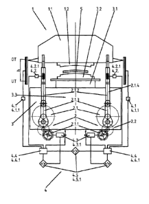
Fig. 1 shows an example of a press 1 with a drive device 2 disposed in a sub-
structure 3 and
connected to drive elements 2.1, 2.1.1, 2,1.2, 2.1.3. A plunger 1.1 executing
a stroke h
between a top dead center OT and a bottom dead center UT comprises an upper
tool part 1.2.
Two pairs of tie rods 2.1.2 and connecting rods 2.1.3 act in this example onto
the plunger 1.1
16
CA 2814928 2017-11-07
for transmission of the drive for the stroke h of the plunger 1.1. The plunger
1.1 with the
upper tool part 1.2 corresponds to a bottom tool part 3.2 disposed on the sub-
structure 3,
wherein the upper tool part 1.2 acts onto a work piece 5 lying on the bottom
tool part 3.2 for
forming. Said drive elements 2.1 comprise two motors 2.1.1 and the tie rods
2.1.2 with
respectively one connecting rod 2.1.3, wherein each forms a drive train 2.1.4.
In this example, the bottom tool part 3.2 is disposed on a table 3.1 belonging
to the sub-
structure 3.
A control and regulation device 4 in charge of operating the press 1 comprises
1. first means 4.1 for collection of first data 4.1.1 of a travel
progression as well as of
a position from the stroke h of the plunger 1.1,
2. second means 4.2 for collection of second data 4.2.1 of forces in the
tie rods 2.1.2
or the connecting rods 2.1.3,
3. third means 4.3 for collection of third data 4.3.1 of values of a power
consumption,
a torque, an electrical current, a rotational speed or a rotational angle of
at least
one of the drive elements 2.1, in this case a motor current,
4. fourth means 4.4 for collection of fourth data 4.4.1 of an actual value of
a power
input or an increase in power input in the system of the press 1 and
5. a fifth means 4.5 for analysis of fifth data 4.5.1 for triggering actions
= for modifying values to be adjusted or put in for the operation of the
press 1,
= for overload protection, emergency operation or shutdown of the press 1
and
= for the synchronous or asynchronous run of the drive elements 2.1, 2.1.1,
2.1.2, 2.1.3
of the drive device 2.
With the plunger 1.1, by way of the acting tie rods 2.1.2 and connecting rods
2.1.3 and as a
consequence of the action of the fifth means 4.5 of the control and regulation
device 4, the
press applies forces acting in a differentiated manner onto the work piece 510
be formed
between the upper tool part 1.2 and the bottom tool part 3.2, as schematically
shown in fig. 2.
image a) and image b).
To this end, values are collected from conditions in the system of the press 1
during
processing of the work piece 5 and data processed according to fig. 2a) in
accordance with the
function
17
CA 2814928 2017-11-07
F(X) = F2 under the condition that L > x >
is fed into the drive device 2 for the movement of the plunger, so that the
press 1 is
permanently operated according to a system of forces required for the work
piece 5.
In the curve according to fig. 2a), F1 and F2 represent as F (x) = x-1: = F2
under the condition
that L > x > -2 the forces acting locally in a controlled manner over the area
L, wherein
refers to the maximally acting force and x to the area of a force acting in a
differentiated or
variable manner according to the invention.
In fig. 2b), the effect according to the invention is schematically compared,
based on forces
LE acting in the extended area in the upper tool part 1.2, to an area Lo
covered to date, i.e.
without the function according of the invention, according to the prior art.
Fig. 2b) thus illustrates as a whole the inventive effect of the forces Fi and
F2 in an area LE >
1,0 as opposed to the forces Lao and F21 acting to date.
The method makes it possible to record and process the values as data
a) of a force and travel progression of the plunger 1.1 according to
the function f (x) =
a(0)/2 +a(1) * cos(1 * x) + + and
b) under the conditions of the stroke h of the plunger 1.1 according to the
formula
a(0)/2 +a(1) * cos(1 * + a(2) * cos(2 * x) + ...+b(1) * sin(1 * x) + b(2) *
sin(2 * x) +
In fig. 1, the method can be observed schematically or in terms of
construction.
To begin with, first data 4.1.1 is collected by the first means 4.1 from
values of the travel
progression or a position from the stroke h of the plunger 1.1.
Then, second data 4.2.1 is collected by the second means 4.2 from the
collection of actual
values of respectively one force or one force equivalent value in the drive
elements 2.1, 2.1.1,
2.1.2, 2.1,3 of the drive device 2, wherein the second data 4.2.1 is
advantageously gained
from the collection of actual values of forces in the tie rods 2.1.2 and
wherein conventional
strain gauges or piezo elements can be disposed in the places of a force to be
measured.
18
CA 2814928 2017-11-07
In the further course, third data 4.3.1 of actual values of the current of the
motors or servo-
motors 2.1.1 of the drive device 2 is collected by the third means 4.3.
.. Finally, fourth data is recorded by thc fourth means 4.4 from the
collection of actual values of
an increase in power output in the system of the press 1.
This data is processed into fifth data 4.5.1 by the fifth means 4.5 and -
adjusted to the values
of data applying to the work piece 5 - transmitted as virtual control signals
via the drive
device 2 and the plunger 1.1 onto the upper tool part 1.2 and the bottom tool
part 3.2 for
forming the work piece 5.
Thus, the forces acting onto the upper tool part 1.2 and the bottom tool part
12 are applied
onto the work piece to be processed, according to the conditions of the work
piece 5, in a
locally differentiated or variable manner and in an optimally extended area LE
- as shown in
fig. 2b).
As a whole, the processed fifth data 4.5.1 are analyzed in a target/actual
comparison of the
first to fourth collected data 4.1.1, 4.2.1, 4.3.1, 4.4.1 and fed, or
regulated and fed as target
values by use of the fifth means (4.5) in order to trigger the following
actions:
= modification of values to be adjusted for or fed into the operation of
the press 1,
= overload protection, emergency operation or for shutdown of the press 1
= synchronous or asynchronous run of drive elements 2.1, 2.1.1, 2.1.2,
2.1.3 of the drive
device 2.
The analyzed fifth data is used also to influence reactions to press forces in
the system of the
press 1 for shock absorption or in case of bending of the plunger 1.1 for a
modified force
distribution.
The orientation, position and amount of the force can be actively modified
depending for
example on the "forming process", so that partial functions of a die cushion
apparatus, not
shown, can be assumed or actively supported as an effect merged with the main
function.
19
CA 2814928 2017-11-07
The data for the overload protection, emergency operation or shutdown of the
press 1 is
triggered before reaching a set value of the first to fourth collected data
4.1.1, 4.2.1, 4.3.1,
4.4.1 and fifth analyzed data 4.5.1 of the required action or reaction force
and measured,
analyzed and, in case of a deviation from the target specification, specified
as a gradient of an
increasing force in one of the drive elements 2.1, 2.1.1, 2.1.2, 2.1.3, for
modification of the
distribution for an action or reaction force, more specifically for an
anticipated learning stroke
h of the plunger 1.1.
According to the method, the press I is operated in such a ratio of the stroke
h of the plunger
1.1 to a length of the connecting rod 2.1.3 that corresponds to a calculation
of the Fourier
series.
In a preferred exemplary embodiment.
- the press 1 is operated from the drive device 2 to the plunger 1.1 via two
drive trains
2.1.4,
- each drive train 2.1.4 is operated by its own motor or servo-motor
2.1,
- each drive train with its motor or servo-motor 1.1 and tie rods 2.1.2
is operated via the
connecting control and regulation device 4,
- the die cushion apparatus (not shown) is operated with a free space 3.3
provided in the
sub-structure 3,
- each drive train 2.1.4 is operated by means of a detachable rotational
or translational
active connection each between the drive train 2.1.4 that is adapted to be
coupled or
decoupled electrically or mechanically in the round trip of the respective
stroke h of
the plunger 1.1.
In a variant, the drive train 2.1.4 can be operated in an electrically or
mechanically coupled or
decoupled manner with the servo-motor 2.1.1, wherein the active connection 2.2
then
comprises at least one of the drive characteristics:
a) a torque or orientation regulation
b) a control/regulation of the force and speed progression
c) a force and torque free operation, =
d) an automatic operation of the press,
e) an external balance or
CA 2814928 2017-11-07
f) an influence of gravity.
In a torque free operating mode of the servo-motor 2.1.1, the plunger 1.1 can
be moved and
this operating mode can be used for secure operational availability of the
press 1.
Therefore, this means that the drive trains 2.1.4 are intentionally driven by
servo-motors 2.1.1
and operated in the operation modes torque or orientation regulation. Thus,
the force and
speed progression of the press 1 can be influenced, respectively controlled
and regulated. As
another (less common) mode, such a servo-drive can also be operated free of
force and torque.
Thus, the press 1 is virtually "left alone". Depending on the use of
complementary
components, such as e.g. an external balance or gravity influences, a plunger
movement will
still occur in the torque-free operating mode of the servo-motors, namely as
illustrated in
figure 2 and 4, which must still be explained. As a whole, this operating mode
is also
advantageous in case of unexpected events, e.g. power outage, since the drives
can then be
switched into the torque-free state as an emergency strategy, thus putting the
press 1 into an
operationally secure state.
In another variant, the active connection 2.2 of the drive train 2.1.4 can be
alternately closed
and opened as a mechanical coupling in a positive-fitting, force fitting or
frictional
engagement.
In order to achieve synchronization or compensation movements of the plunger
1.1, the drive
trains 2.1.4 are operated in a coupled manner during at least part of the
downward stroke h
and in a decoupled manner during at least part of the upward stroke h.
Depending on at least one of the values or gradients of the forming forces,
speed or travel to
be transmitted or one of the positions of the work step of forming, the drive
elements 2.1 or
the position of the plunger 1.1, the active connections 2.2 are closed or
released or influenced
depending on the force and orientation.
A speed of the plunger 1.1 moving downward from or ahead or after a top dead
center OT is
slowed down just before the plunger 1.1 connected to the upper tool part 12
impacts on the
bottom tool part 3.2, in order to reduce a percussion-type stress, and after
the impact of the
upper tool part 1.2, the plunger 1.1 is moved in a controlled or regulated
manner downwards
to the bottom dead center UT and then upwards.
21
CA 2814928 2017-11-07
Fig. 3 graphically shows how in a variant, the plunger 1.1 is moved downward
ahead of or
from its upper dead center by means of its own gravity until shortly before
impacting on e.g.
an element of the die cushion apparatus, wherein the plunger is thereby slowed
down by
means of a generator operation of the motor 2.1 (fig. 1), in order to reduce
the impact of the
plunger 1.1 on the element of the die cushion apparatus (not shown), such as
e.g. a
conventional support or a conventional pressure cheek, and the element of the
die cushion
apparatus is subsequently moved downward at a controlled speed and the work
piece 5 (fig. 1)
is formed and the plunger 1.1 is subsequently moved to the upper dead center
or to the upper
end position OT.
Fig. 4 graphically illustrates how the plunger 1.1 is moved downward from its
upper dead
center OT in a controlled drive, wherein all the required values or gradients
of a speed can be
determined at the impact on the element of the die cushion apparatus (as
explained above)
based on a forming speed, and how the plunger 1.1 is moved from the upper dead
center or to
the upper end position OT after forming the work piece 5.
After forming the work piece 5, the plunger 1.1 is driven to the upper dead
center OT or the
upper end position with the aid of force application.
In case of asymmetrically acting forces, e.g. in the die cushion apparatus,
independent force
applications onto the plunger 1.1 occur via the separately operated drive
trains 2.1.4, which
ensure a guidance of the original, i.e. the intended movement of the plunger
1.1 as well as a
parallel movement of the upper tool part 1.2 relative to the bottom tool part
3.2, said force
applications preventing a skew of the plunger 1.1 as well as different impact
blows of the
pltmger 1.1.
On the other hand, the exemplary embodiment also allows advantageously using
asymmetrically acting forces of the plunger 1.1 and thus generating them by
the plunger 1.1
impacting parallel onto the die cushion apparatus for example, respectively in
the absence of a
die cushion apparatus by the plunger being moved parallel with the upper tool
part so that it
comes to bear on the bottom tool part. To this end, the two drive trains 2.4
arc moved a
different distance in the direction of the bottom dead center UT, without
however reaching it.
Subsequently, a reversion (inversion of the rotational direction of the drive)
and the upward
movement of the plunger 1.1 occur.
22
CA 2814928 2017-11-07
Alternatively, a drive train 2.1.4 can even travel through the bottom dead
center UT and back
to the upper dead center without reversion, whereas the other drive train
2.1.4 is reversed and
travels back to the upper dead center UT before reaching the bottom dead
center UT.
The generation of the actually active force is derived from the respective
position of the
respective drive train 2.1.4 or e.g. of an off-center element of the drive
device 2 by taking into
account the rigidity of the machine (Hooke's law).
Based on this teaching, the press 1 is implementable in the following manner:
In principle, in case of asynunetrically acting forces, the plunger 1.1 is
first movable in
parallel from the upper dead center OT in the direction of the bottom dead
center UT and a
resulting unequal movement of the two drive trains 2.1.4 can now continue
after the upper
tool part 1.2 has impacted on the bottom tool part 3.2. The upper tool part
1.2 and the bottom
tool part 3.2 are now closable in parallel. Due to the unequal continuing
movement,
asymmetrically and unequally acting forces become producible via the spring
rigidity of the
press 1.
According to a variant, the plunger 1.1 and the drive trains 2.1.4 are movable
in the direction
of the top dead center (OT) before reaching the bottom dead center UT and upon
achieving
the asymmetrically and unequally acting forces in the reversing operation
(inversion of the
rotational direction of the drive device), wherein the upper tool part 1.2 is
movable away from
the bottom tool part (3.2).
According to another variant, the press 1 can also be operated in such a
manner that the
greater force acting respectively in a drive train 2.1.4 is considered as a
guiding value and said
drive train 2.1.4 can be driven through the bottom dead center UT and then
toward the top
dead center OT without reversing operation. The other drive train 2.1.4 with
the lesser acting
force is configured so that it will stop before the bottom dead center UT and
is reversible.
Together with the first mentioned drive train 2.1.4, the plunger 1.1 will be
drivable along with
the upper tool part 1.2 in a parallel movement to the bottom tool part 3.2
back to the top dead
center OT.
23
CA 2814928 2017-11-07
The method for operating the press described in the exemplary embodiment uses
a program,
which is adapted to be integrated into the control and regulation device 4, in
which the
following program functions are provided:
a) Processing the first to fifth data according to the function F(x) = = F2
under the
condition that L > x > - so that the press (1) can be permanently operated in
a
2
regulated and controlled manner according to a system of forces required for
the work
piece 5 in accordance with the conditions of the work piece 5 to be processed,
b) Processing the first to fifth data according to a force and travel
progression of the
plunger (1.1) according to the function f (x) = a(0)/2 + a(1) * cos(1 * x) + =
= = +
and under the conditions of the stroke (h) of the plunger (1.1) according to
the formula
a(0)/2 + a(1) * cos(1 * x) + a(2) cos(2 * x) + === + b(1) * sin(1 * x) + b (2)
*
sin(2 * x) + =-,
c) Processing the collected first to fourth and analyzed fifth data as
controllable and
adjustable target specifications for the drive device 2 and the movement of
the plunger
1.1, so that the forces to be transmitted by the upper tool part 1.2 and the
bottom tool
part 3.2 can act on the work piece in a locally differentiated manner,
d) activation of commands for triggering actions
o for modifying values to be adjusted or put in for the operation of the
press 1,
o for overload protection, emergency operation or shutdown of the press 1
or
o for the synchronous or asynchronous run of drive elements 2.1, 2.1.1, 2.1.2,
2.1.3 of the drive device 2 and
activation of commands for influencing reactions to the press force in the
system of
the press 1 for shock absorption or in case of bending of the plunger 1.1 for
a modified
force distribution.
e) specification of an operation algorithm for press guidance according to the
required
and possible work processes of the press 1 and,
f) visual presentation on a display of information relevant to the press from
the operation
algorithm, more specifically regarding operation sequences, operation
situations and
required interventions with interfaces for said program functions for
respective
integration into the programmed operation of a transfer press or press line as
well as in
peripheral functions, such as the programmed operation of a die cushion and/or
a
transfer device.
24
CA 2814928 2017-11-07
Industrial applicability
The press with a bottom drive operated according to the method by means of a
control and
regulation device with an optimized force and travel progression of the
plunger and its stroke
guarantees an energy-saving operation to the user through forces that act and
are used in a
more efficient manner and simultaneously establishes the pre-condition
required to be able to
build the press with optimized performance data in a more compact way than
with
conventional presses with sub-structures.
CA 2814928 2017-11-07
List of reference numbers
1 = press
1.1 = plunger
1.2 = upper tool part
2 = drive device
2.1 = drive element
2.1.1 = motor or servo-motor
2.1.2 = tie rod
2.1.3 = connecting rod
2.1.4 = drive train
2.2 = translational or rotational active connection
3 = sub-structure
3.1 = table
3.2 = bottom tool part
3.3 = free space
4 = control and regulation device
4.1 = first means for collection of first data
4.1.1 = first data of a travel progression and of a position from the
stroke h of the
plunger (1_1)
4.2 = second means for collection of second data
4.2.1 = second data of a force in at least one tie rod 2.1.2 or one
connecting rod 2.1.3
4.3 = third means for collection of third data
4.3.1 ¨ third data of values of a power consumption, a torque, a
rotational speed, an
electrical current, or a rotational angle of at least one drive element 2.1,
such as
a motor 2.1.1
4.4 fourth means for collection of fourth data
4.4.1 fourth data of at least one actual value of a power output or of an
increase in
power output in the system of the press 1
4.5 fifth means for processing, regulation and control of fifth dta
4.5.1 fifth data for triggering at least one of the actions and
reactions
26
CA 2814928 2017-11-07
S = work piece
= stroke, learning stroke
F(x) ¨ force according to function controlled according to the invention
F1 = locally acting force according to the invention
Flu) = force acting according to the prior art
F2 = locally acting force according to the invention
F2L0 = forcc acting according to the prior art
F maximum force according to the invention
= area of a variably acting force according to the invention
LE = variable area of acting forces according to the invention (LE >
L0)
= fixed area of acting forces according to the invention
OT = top dead center
UT = bottom dead center
27
CA 2814928 2017-11-07