Language selection

Search

Patent 2815015 Summary

Third-party information liability

Some of the information on this Web page has been provided by external sources. The Government of Canada is not responsible for the accuracy, reliability or currency of the information supplied by external sources. Users wishing to rely upon this information should consult directly with the source of the information. Content provided by external sources is not subject to official languages, privacy and accessibility requirements.

Claims and Abstract availability

Any discrepancies in the text and image of the Claims and Abstract are due to differing posting times. Text of the Claims and Abstract are posted:

  • At the time the application is open to public inspection;
  • At the time of issue of the patent (grant).
(12) Patent: (11) CA 2815015
(54) English Title: LIFTING TOOL FOR OPPOSING TWISTING OF GENERALLY SUBMERGED ROPES
(54) French Title: OUTIL DE LEVAGE POUR LA TORSION OPPOSEE DE CABLES GENERALEMENT IMMERGES
Status: Granted
Bibliographic Data
(51) International Patent Classification (IPC):
  • B66C 13/02 (2006.01)
  • B63B 27/10 (2006.01)
  • B66C 13/04 (2006.01)
(72) Inventors :
  • BOROY, YNGVAR (Norway)
(73) Owners :
  • GRANT PRIDECO, INC. (United States of America)
(71) Applicants :
  • NATIONAL OILWELL VARCO NORWAY AS (Norway)
(74) Agent: RIDOUT & MAYBEE LLP
(74) Associate agent:
(45) Issued: 2019-01-15
(86) PCT Filing Date: 2011-11-02
(87) Open to Public Inspection: 2012-05-10
Examination requested: 2016-11-02
Availability of licence: N/A
(25) Language of filing: English

Patent Cooperation Treaty (PCT): Yes
(86) PCT Filing Number: PCT/NO2011/000308
(87) International Publication Number: WO2012/060715
(85) National Entry: 2013-04-17

(30) Application Priority Data:
Application No. Country/Territory Date
20101540 Norway 2010-11-03

Abstracts

English Abstract

Summary A lifting tool (1) for opposing twisting of generally submerged ropes (6, 12) the lifting tool (1) comprising a body (30) with a centre axis (48), and having an operable lock (32) that is adapted to catch a rope connector (16, 32), and a structure (46) that is designed to be connected to a hoist or crane (2), wherein the lifting tool (1) is equipped with at least one water flow inducing means positioned at a radial distance from the centre axis (48).


French Abstract

L'invention porte sur un outil de levage (1) pour la torsion opposée de câbles généralement immergés (6, 12), l'outil de levage (1) comportant un corps (30) ayant un axe central (48), et ayant un dispositif de verrouillage utilisable (32) qui est conçu pour capturer un connecteur de câble (16, 32) et une structure (46) qui est conçue pour être reliée à un treuil ou à une grue (2), l'outil de levage (1) étant équipé d'au moins un moyen induisant un écoulement d'eau positionné à une distance radiale de l'axe central (48).

Claims

Note: Claims are shown in the official language in which they were submitted.

6
WE CLAIM:
1. A lifting tool for opposing twisting of generally submerged ropes, the
lifting tool
comprising: a body with a center axis, the body having a lock configured to
selectively limit movement of a rope connector through the body; a structure
coupled to the body and configured to couple to a hoist or crane; at least one
rudder
positioned at a radial distance along a radial axis from the center axis, the
at least
one rudder having a shape that is substantially symmetrical about the radial
axis;
and a control unit configured to alter a position of the at least one rudder
to oppose
rotation of the lifting tool.
2. The lifting tool according to claim 1 wherein the rudder is adjustable
with respect
to a fluid flow direction.
3. The lifting tool according to claim 1 wherein the lifting tool comprises
a pair of
rudders positioned on opposite sides of the lifting tool.
4. The lifting tool according to claim 1 wherein the rudder is turnable
about the radial
axis in the direction of a span of the rudder.
5. The lifting tool according to claim 1 further comprising an actuator to
turn the
rudder about the radial axis in the direction of the span of the rudder.
6. The lifting tool according to claim 5 wherein energy for operation of
the actuator
is stored on the lifting tool.
7. The lifting tool according to claim 6 wherein the energy is stored in
the form of a
pressurized fluid.
8. The lifting tool according to claim 6 further comprising a battery to
store the energy
for operation of the actuator.
9. The lifting tool according to claim 1 further comprising: a sensor to:
detect a
rotational acceleration or inclination of the body; and generate data
indicative of a

7
value of the rotational acceleration or inclination of the body; and wherein
the
control unit is further configured to: receive the data from the sensor; and
alter the
position of the rudder based on the data from the sensor.
10. The lifting tool according to claim 9 wherein the rudder control unit
further
comprises an actuator to alter the position of the rudder about the radial
axis in the
direction of the span of the rudder.
11. The lifting tool according to claim 1, wherein the at least one rudder
has a truncated
shape.
12. The lifting tool according to claim 1, wherein the at least one rudder
comprises a
tip chord and a root chord, the tip chord and the root chord defined by linear
edges.
13. The lifting tool according to claim 12, wherein the root chord is
configured to be
longer than the tip chord.

Description

Note: Descriptions are shown in the official language in which they were submitted.


CA 02815015 2013-04-17
WO 2012/060715 PCT/N02011/000308
1
LIFTING TOOL FOR OPPOSING TWISTING OF GENERALLY SUBMERGED ROPES
There is provided a lifting tool for opposing twisting of generally submerged
ropes.
More precisely, there is provided a lifting tool for opposing twisting of
generally sub-
merged ropes where the lifting tool comprises a body having an operable lock
that is
adapted to catch a rope connector, and a structure that is designed to be
connected to
a hoist or a crane.
During hoisting operations at sea where heavy items having weights in the
order of
several hundred tonnes are to be disposed on the seabed, the availability of
steel
ropes having sufficient combined strength and length has become a limiting
factor for
the size of items that can be handled. The seabed may be located several
kilometres
below sea level, and the weight of the steel rope therefore becomes
significant.
It may therefore be necessary to use fibre ropes that have a density close to
that of
water, to allow the largest items to be submerged into deep waters.
The use of fibre ropes for operations of this type requires consideration of
conditions
not normally being limiting when using steel ropes. For example, the effective
life of a
fibre rope comprising a significant proportion of carbon fibre, depends
directly on the
number of load-related flexures that the fibre rope is exposed to.
Oftentimes hoisting operations of this type are heave-compensated, and the
lifting
rope will therefore be continuously reeled in and out from a winch due to the
heave
motion of the lifting vessel. Even if the item being lifted is stationary
relative to the
seabed, the lifting rope will still be reeled in and out, whereby the
effective life of a
fibre rope is reduced relatively fast.
NO document 20090729 discloses a method for paying out a relatively long fibre
rope,
which carries a load, by means of a shorter steel rope. The method, that
includes the
use of parallel ropes, is explained in detail in the special part of this
document.
An inherent problem when utilizing parallel ropes is the tendency of the rope
to twist

CA 02815015 2013-04-17
WO 2012/060715 PCT/N02011/000308
2
and to get entangled in each other. As the ropes have to be moved
independently of
each other in the sea, an entanglement may in a worst case lead to cutting of
the
ropes and loss of a valuable item.
The object of the invention is to remedy or reduce at least one of the
disadvantages of
the prior art.
The object is achieved according to the invention by virtue of the features
disclosed in
the description below and in the subsequent claims.
There is provided a lifting tool for opposing twisting of generally submerged
ropes, the
lifting tool comprising a body with a centre axis, and having an operable lock
that is
adapted to catch a rope connector, and a structure that is designed to be
connected to
a hoist or a crane wherein the lifting tool is equipped with at least one
water flow in-
ducing means positioned at a radial distance from the centre axis.
The water flow inducing means may be adjustable and include one or more of a
thruster, a nozzle or a rudder.
When lifted or lowered through the sea, the thruster, the nozzle or rudder may
be ad-
justed to oppose a torque from one or both ropes. By measuring one or more
physical
features such as the rotational acceleration or inclination, the thruster, the
nozzle or
the rudder may be adjusted autonomously, remote by an operator, ore by a
combina-
tion thereof to counteract said torque.
Equipment and methods usable for such measurements and control are well known
to
a skilled person and is not explained here.
The lifting tool may have a pair of thrusters, nozzles and rudders where the
thrusters,
nozzles or rudders are positioned on opposite sides of the lifting tool. When
adjusting
the pair of thrusters, nozzles or rudders properly, a couple acting about the
central
axis of the payload carrying rope may be generated.
The rudder may be turnable about an axis laid out in the direction of the span
of the
rudder. Thus the rudder may be balanced so that less torque is needed in
adjusting
the rudder.
The thrusters, nozzle or rudder may be connected to an actuator for the
adjustment
about said axis. Energy for operation of the actuator and for the thrusters
may be
stored on the lifting tool.

CA 02815015 2013-04-17
WO 2012/060715 PCT/N02011/000308
3
The energy may for instance be stored in the form of a pressurized fluid or an
electri-
cal charge.
Water flow for the nozzle may be generated from the speed of the lifting tool
through
the sea. The nozzle inlet may be positioned in the lifting direction, while
the outlet of
the nozzle may be directed tangentially relative the lifting tool body.
It may be advantageous to combine a thruster for use when the lifting tool is
station-
ary in the sea, and a rudder for use when the lifting tool is at speed, this
in order to
conserve energy. While in motion, a thruster may be used for generating
energy. The
thruster and rudder may be one unit or separate items
The lifting tool may, when it is connected to the steel rope and either moving
along, or
carrying the fibre rope, oppose the rotational forces typically generated by
torque
from the ropes, sea current and vortex shredding, and acting on the lifting
tool. The
lifting tool may thus, when having a speed through the sea, largely prevent
the twist-
ing and entanglement between parallel ropes in the sea.
Below, an example of a preferred lifting tool is explained under reference to
the en-
closed drawings, where:
Fig. 1 shows the general layout of a lifting operation;
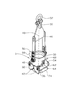
Fig. 2 shows in perspective and larger scale a lifting tool according to
the inven-
tion; and
Fig. 3 shows a side view, partly sectioned, of the lifting tool in fig. 2.
On the drawings the reference number 1 denotes a lifting tool that is
connected to a
crane 2 on a vessel 4 by a steel rope 6 and a lifting hook 8, the lifting hook
8 includes
a swivel not shown.
A first fibre rope section 10 of a fibre rope 12 is passing through the
lifting tool 1. The
first fibre rope section 10 is at its lower end party connected to an item 14
via a first
rope connector 16 and an intermediate rope 18. At its opposite upper end the
first
fibre rope section 10 is connected to a second fibre rope section 20 via a
second rope
connector 22.
The second fibre rope section 20 extends over a sheave 24 on the crane 2, to a
feed
mechanism 26 on the vessel 4.

CA 02815015 2013-04-17
WO 2012/060715 PCT/N02011/000308
4
In fig. 1 the second rope connector 22 is shown in a locked position in a
hanger 28 on
the crane 2. The lifting force generated by the item 14 is thus carried by the
first fibre
rope section 10 and the crane 2, and not by the second fibre rope section 20.
The lifting tool 1 includes a pipe formed body 30 having an operable lock 32
that is
adapted to catch a rope connector 10, 22 as the fibre rope 12 passes through
the
body 30.
In the shown embodiment, see fig. 3, the lock 32 includes a first lock party
34 that is
fixed to a first shaft 36, and a second lock party 38 that is fixed to a
second shaft 40.
Other forms of locking mechanisms may be applicable.
The two shafts 36, 40 are rotationally interconnected by toothed sectors 42.
The lock
parities 34, 38 are movable by a lock actuator, not shown, between an active
locked
position as shown in fig. 3, where the lock parties 34, 38 rest on a
protrusion 44 in the
body 30, and an open position, not shown, where the lock parties 34, 38 are
turned
upwardly so the rope connector 10 may pass through the body 30.
An upper structure 46 is pinned to the body 30 and allowed to swing a limited
amount
out from the centre axis 48. The structure 46 includes a padeye 50 for a
shackle 52.
The body 30 is equipped with a first rudder 54 and a second rudder 56
protruding with
their span 58 in a radial direction of the body 30. As the first and second
rudders 54,
56 are connected to the body 30 by bearings 60, the first rudder 54 may be
turned
about a first axis 62 by a first actuator 64 while the second rudder 56 may be
turned
about a second axis 66 by a second actuator 68.
The rudders 54, 56 of the present embodiment are substantially symmetrical
about
the respective axis 60, 64. The axes 60, 64 are generally parallel with the
span 58 and
the rudder's 54, 56 root cord 70 are longer than their tip cord 72.
Eqipment, cables and pipes for the operation of for instance the actuators 62,
66 are,
apart from containers 74 for pressurised drive fluid, not shown on the
drawings.
When an item 14 is to be lowered into the sea 76 and down to the sea floor 78,
the
first rope connector 16 as shown in fig. 3 is prevented from passing through
the body
by the lock 32.
30 The first fibre rope section 10 is paid out from the feed mechanism 26
while the crane
2 is carrying the payload from the item 14 via the steel rope 6, the lifting
tool 1, the
first rope connector 16 and the intermediate rope 18.

CA 02815015 2013-04-17
WO 2012/060715 PCT/N02011/000308
As the lifting tool 1 descends through the sea 76, the rudders 54, 56 are
adjusted to
oppose torques from the sources described above.
When the second rope connector 22 interlocks with the hanger 28, the payload
is tak-
en over from the steel rope 6 by the first fibre rope section 10.
5 The lifting tool 1 is released from the first rope connector 10 by moving
the lock par-
ties 34, 38 to their open position. The lifting tool 1 may be moved upwardly
along the
first fibre rope section 10, the rudders opposing rotation of the lifting tool
1, see fig. 1.
The lifting tool 1 then latches in with the second rope connector 22. When the
hanger
28 unlatches from the second rope connector 22, the crane may lower the first
fibre
rope section 10, now carrying the payload, while the second fibre rope section
20 is
paid out over the sheave 24 largely unloaded.

Representative Drawing
A single figure which represents the drawing illustrating the invention.
Administrative Status

For a clearer understanding of the status of the application/patent presented on this page, the site Disclaimer , as well as the definitions for Patent , Administrative Status , Maintenance Fee  and Payment History  should be consulted.

Administrative Status

Title Date
Forecasted Issue Date 2019-01-15
(86) PCT Filing Date 2011-11-02
(87) PCT Publication Date 2012-05-10
(85) National Entry 2013-04-17
Examination Requested 2016-11-02
(45) Issued 2019-01-15

Abandonment History

There is no abandonment history.

Maintenance Fee

Last Payment of $263.14 was received on 2023-09-13


 Upcoming maintenance fee amounts

Description Date Amount
Next Payment if standard fee 2024-11-04 $347.00
Next Payment if small entity fee 2024-11-04 $125.00

Note : If the full payment has not been received on or before the date indicated, a further fee may be required which may be one of the following

  • the reinstatement fee;
  • the late payment fee; or
  • additional fee to reverse deemed expiry.

Patent fees are adjusted on the 1st of January every year. The amounts above are the current amounts if received by December 31 of the current year.
Please refer to the CIPO Patent Fees web page to see all current fee amounts.

Payment History

Fee Type Anniversary Year Due Date Amount Paid Paid Date
Application Fee $400.00 2013-04-17
Maintenance Fee - Application - New Act 2 2013-11-04 $100.00 2013-10-10
Maintenance Fee - Application - New Act 3 2014-11-03 $100.00 2014-10-06
Maintenance Fee - Application - New Act 4 2015-11-02 $100.00 2015-09-24
Maintenance Fee - Application - New Act 5 2016-11-02 $200.00 2016-10-05
Request for Examination $800.00 2016-11-02
Maintenance Fee - Application - New Act 6 2017-11-02 $200.00 2017-10-16
Maintenance Fee - Application - New Act 7 2018-11-02 $200.00 2018-10-10
Final Fee $300.00 2018-11-20
Maintenance Fee - Patent - New Act 8 2019-11-04 $200.00 2019-10-09
Maintenance Fee - Patent - New Act 9 2020-11-02 $200.00 2020-10-07
Maintenance Fee - Patent - New Act 10 2021-11-02 $255.00 2021-09-22
Maintenance Fee - Patent - New Act 11 2022-11-02 $254.49 2022-09-14
Registration of a document - section 124 2022-12-06 $100.00 2022-12-06
Maintenance Fee - Patent - New Act 12 2023-11-02 $263.14 2023-09-13
Owners on Record

Note: Records showing the ownership history in alphabetical order.

Current Owners on Record
GRANT PRIDECO, INC.
Past Owners on Record
NATIONAL OILWELL VARCO NORWAY AS
NOV INTERNATIONAL HOLDINGS C.V.
Past Owners that do not appear in the "Owners on Record" listing will appear in other documentation within the application.
Documents

To view selected files, please enter reCAPTCHA code :


To view images, click a link in the Document Description column. To download the documents, select one or more checkboxes in the first column and then click the "Download Selected in PDF format (Zip Archive)" or the "Download Selected as Single PDF" button.

List of published and non-published patent-specific documents on the CPD .

If you have any difficulty accessing content, you can call the Client Service Centre at 1-866-997-1936 or send them an e-mail at CIPO Client Service Centre.


Document
Description 
Date
(yyyy-mm-dd) 
Number of pages   Size of Image (KB) 
Abstract 2013-04-17 2 61
Claims 2013-04-17 1 30
Drawings 2013-04-17 3 44
Description 2013-04-17 5 199
Representative Drawing 2013-05-23 1 8
Cover Page 2013-06-26 2 41
Claims 2016-11-02 1 29
Examiner Requisition 2017-10-06 4 214
Amendment 2018-04-06 9 275
Claims 2018-04-06 2 51
Final Fee 2018-11-20 1 48
Representative Drawing 2018-12-19 1 7
Cover Page 2018-12-19 1 36
PCT 2013-04-17 2 78
Assignment 2013-04-17 5 118
Amendment 2016-11-02 5 128