Note: Descriptions are shown in the official language in which they were submitted.
CA 02815032 2013-04-30
1
Title: COUPLER-ASSEMBLY FOR ATTACHING BUCKET OR THE LIKE TO
ARTICULATING ARM
[001] This technology relates to front-end loaders, or the like, being
vehicles equipped
with a movable articulating mast or arm, to which a bucket can be attached,
and relates
especially to a coupling-assembly for incorporation into, and for use with,
such vehicles.
[002] LIST OF DRAWINGS
Figs.1A,1B,1C,1D are side elevations of the articulable arm of a front-end-
loader being
operated to pick a bucket from the ground, shown in four stages.
Fig.2 is a pictorial view of a coupler-assembly of Fig.1, carried on the
distal end of the arm.
Fig.3 is a similar view, showing an arm-end of the coupler-assembly coupled
to, and locked
to, bucket-lugs of a materials-handling bucket.
Fig.3A shows a side-plate of the frame of the coupler-assembly, as a separate
component.
Fig.4 is a similar view again, showing a sliding-block of the coupler-
assembly, and a
connecting hydraulic supply hose.
Figs.5A,5B are plan views of the coupler-assembly, shown at different stages
of operation.
Fig.5C is a plan view of a frame of the arm-end of the coupler-assembly.
Figs.6A,66 are side elevations of the coupler-assembly, shown at different
stages of
operation.
Fig.7A is a front elevation of the coupler-assembly.
Fig.7B is the same front elevation, but shows the dirt-shields carried by the
sliding-block.
Fig.8 is a pictorial view of the slider-block and associated components.
Figs.8A,8B shows tenon wedges of the slider-block.
Figs.9A,913,9C,9D are diagrams depicting stages in the release of the bucket
from the
coupler-assembly.
Figs.10A,10B are diagrams depicting stages in the coupling of a bucket to the
coupler-
assembly.
Figs.11A,11B are similar diagrams depicting another form of coupler-assembly.
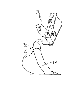
[003] Fig.1A shows a bucket 20 resting on the ground, and about to be picked
up by a
coupler-assembly 21 mounted on the articulating mast or arm 23 of a front-end-
loader. The
coupler-assembly 21 includes an arm-end 25, the frame 27 of which is pivoted
to the arm
23 at an arm-end pivot-pin 29. In Fig.1A, the driver of the front-end-loader
has manipulated
CA 02815032 2013-04-30
2
the arm 23, and the arm-end 25, in such manner that the coupler-assembly 21 is
about to
snag the bucket-lugs 30 which are integrated into the bucket 20.
[004] In Fig.1B, the bucket-lugs 30 have been hooked onto the pivot-pin 29.
However,
the bucket 20 is not at all securely attached to the arm 23 at this stage. In
Fig.1C, the
driver has rotated the arm-end 25 about the pivot-pin 29 such that the bucket-
lug 30 lies
snugly nestled between the pivot-pin 29 and a cheek-piece 32, which is
integrated into a
side-plate 34 of the arm-end frame 27. However, securement of the bucket 20 to
the arm
23 is still not complete.
[005] In Fig.1 D, a tenon 36 of the coupler-assembly 21 has been advanced, and
has now
engaged a mortise 38, formed in the bucket-lug 30. Hydraulic pressure is
maintained, in
the coupler-assembly, at all times while the bucket is in operation. The
coupler-assembly
includes a lock-bolt 40, which enters a lock-slot 41 in the side-plate of the
frame 27. If the
hydraulic pressure were to fail, for example, the presence of the lock-bolt 40
in the lock-slot
41 would ensure that the bucket 20 cannot fall off the arm 23.
[006] Fig.2 shows the arm-end 25 of the coupler-assembly 21 mounted to arm 23.
No
bucket is attached, in Fig.2, and the tenon 36 is in its withdrawn-position as
shown in
Figs.1A,113,1C.
[007] Fig.3 shows the bucket-lugs 30 now firmly and securely held with respect
to the
arm-end 25. The tenon 36 is tightly engaged into the mortise 38, and is held
tight by
hydraulic pressure. The lock-bolt 40 is engaged in the lock-slot 41, whereby
the tenon 36
cannot release from the mortise 38, for security of attachment.
[008] Fig.4 shows some of the components that lie inside the frame 27 of the
arm-end 25.
The major component is the slider-block 43. The left and right tenons 36 are
integrated
into the slider-block. The hydraulic hose 45 (there are two hoses to the
coupler-assembly,
but only one is shown) conveys hydraulic oil from the mast or arm 23 of the
front-end-
loader or similar vehicle to the slider-block 43.
[009] The end 49 of the hose 45 is mounted on the arm 23, rather than on the
arm-end
25. The hoses have to accommodate the full range of pivoting movement of the
arm-end
CA 02815032 2013-04-30
3
25 about the pivot-pin 29. The hoses 45 have to accommodate the sliding
movement of
the slider-block 43 as well, but it is recognized that, by the time the hoses
45 have been
arranged to accommodate the full range of pivoting movement, the small extra
movement
required for the movement of the slider 43 is insignificant. The hose 45 can
be guided with
respect to the frame of the arm-end, but preferably the end 49 of the hose
should not be
fixed to the arm-end.
[0010] A hydraulic slider-ram 47 is built into the slider-block 43. A piston-
rod 50 of the
slider-ram 47 is movable relative to the slider-block, and the ram is operable
to move the
slider-block 43 to and fro, thereby moving the left and right tenons 36 into
and out of
engagement with the left and right mortises 38. A bolster 52 is fixed to the
floor 54 of the
frame 27 of the arm-end 25. The piston-rod 50 is clamped to the bolster 52,
and thus to
the frame 27. The cylinder of the slider-ram 47 is integrated into the slider-
block 43. The
bolster 52 is suitably buttressed to support the (considerable) forces created
by the slider-
ram 47.
[0011] As shown in Fig.4, inside and outside dirt-shields 56,58 are mounted on
the tenons
36. (In some views, these dirt shields are not shown, for clarity.)
Figs.8,8A,8B show the
dirt-shields, which are integrated into (in this case, welded to) the tenons
36. As shown in
Fig.7B, the side-plate 34 of the frame 27 is sandwiched between the inside and
outside
dirt-shields 56,58. The dirt-shields should not touch the side-plate 34, but
should have a
running clearance. The clearance should be small enough to keep out dirt
particles that
are large enough possibly to interfere with the guides and slides.
[0012] Actually sealing the slider-slots 60 (and the lock-slot 41) might be
preferred, but
actual sealing is difficult.
[0013] As shown in Figs.8,8A,8B, the tenons are formed with respective
cylindrical tenon-
pins 63. The tenon-pins 63 fit into corresponding cylindrical holes formed in
the slider-
block. The tenon-pins 63 are locked into the holes by dowels 65, and also the
inside dirt-
shields 56, which are welded to the tenons 36, are bolted to the slider-block
43. Thus, the
tenons are well-integrated into the slider-block 43.
[0014] Figs.5A-7B show how the slider-block 43 is constrained, in/by the arm-
end frame
CA 02815032 2013-04-30
4
27, against all modes of movement relative to the frame -- other than out-and-
back sliding
under the forces arising from the slider-ram 47.
[0015] The side-plates 34 of the frame 27 are formed with slider-slots 60. The
tenon 36 is
formed with upper 61 and lower slide-surfaces, which fit (with suitable
clearance) between
the upper and lower walls of the slider-slot 60. The engagement of the slide-
surfaces of
the tenons 36 with the walls of the slider-slots 60 in the arm-end frame 27
constrain the
tenons (and with them, the slider-block 43) against up/down movements, and
against roll-
mode tipping of the slider-block. However, the engagement of the tenons 36 in
the slider-
slots 60 does not constrain the slider-block 43 against yaw-mode rotation, nor
against side-
to-side translational movements.
[0016] The presence of the dirt-shields 56,58, as shown in Fig.7B, might be
considered to
provide the required anti-yaw and side-to-side constraints. However, relying
on the dirt-
shields for this purpose is not preferred. Rather, guide-rails 57 are
provided, which are
integrated into the floor 54 of the frame 27 of the arm-end 25, and a guide-
recess 69 is
provided in the slider-block 43, and the sides of the recess 69 engage (with
suitable
clearance) the sides of the guide-rails 67. It is this engagement that
provides the required
constraint against side-to side movements and against yaw-mode rotation of the
slider-
block 43.
[0017] Neither the engagement of the tenons 36 with the slider-slots 60, nor
the
engagement of the guide-recess 69 with the guide-rails 67, are effective to
fully constrain
the slider-block 43 against pitch-mode tipping. That constraint comes from the
engagement of the piston-rod 50 of the slider-ram 47 with the bolster 52 of
the arm-end
frame 27.
[0018] The designers should see to it that the (very large) forces arising
from the slider-ram
47 are applied in such manner as to avoid giving rise to unwanted tendencies
of the slider-
block 43 to tip and move in ways that will or might induce heavy contact
forces in the sliding
guides and components. Thus, the line of action of the slider-ram 47 should be
symmetrically between the side-plates 34, and symmetrically between the upper
and lower
walls of the slider-slots 60. Also, the line of action of the ram should be
parallel to the
guide surfaces, to minimize forceful (and thus high frictional) contact within
the guides.
CA 02815032 2013-04-30
[0019] Designers will understand, from a perusal of the drawings, just how
very robustly
the slider-block 43 is constrained and guided with respect to the frame 27.
During
operations, it can be expected that situations will arise that inhibit the
smooth functioning of
the slides and guides -- perhaps due to poor maintenance, presence of caked
dirt, and the
like. If the arm-end were to be encased in set concrete, the present coupler-
assembly
might not be able to cope with that -- but designers should expect the present
design to
provide such high rigidity and robustness of the slider-block and its guides
that the
assembly will cope with anything short of that.
[0020] It is important that the tenon be very tight in the mortise, during
operation, such that
there can be no relative movement between the bucket and the arm-end. The
bucket-lug
30, having been snagged, nestles between the cheek-piece 32 and the pivot-pin
29. The
required tightness of the bucket relative to the arm-end arises because the
bucket-lug can
be wedged into the space between the cheek 32 and the pivot-pin 29. The wedge-
surface
70 on the tenon 36 engages the mortise 38, and drives the mortise in the
upwards direction
(in Fig.3), i.e the counter-clockwise sense, whereby the bucket-lug 30 is
driven more deeply
into the space between the cheek 32 and the pivot-pin 29.
[0021] The force on the tenon 36 (arising from the slider-ram 47) is large,
but that force is
multiplied by the wedge action of the tenon 36 on the bucket-lug 30, and is
multiplied again
by the wedge action of the engagement of the bucket-lug between the cheek and
the pivot-
pin.
[0022] Fig.9A is a diagram showing the arrangement of the slider components
during
operations with the bucket 20. The bucket is held tightly with respect to the
frame 27 of the
arm-end 25. In Fig.9A, the driver has commenced the operation of detaching the
bucket.
The driver has switched the hydraulics such that the port-P is now connected
to pressure,
while the port-Q is connected to drain.
[0023] Now, oil flows into the sequence-valve 72 and passes into a lock-ram
74. In the
sequence valve 72, the rising pressure acts over the (small) area of the valve-
seat 76,
creating an upward force on the sequence-piston 78. This force is opposed by
the
sequence-spring 80, which urges the sequence-piston 78 into contact with the
valve-seat
76. The sequence-spring force is set at a level such that the hydraulic
pressure needed to
CA 02815032 2013-04-30
6
blow the sequence-piston 78 off the valve-seat 76 is higher than the pressure
needed to
drive the lock-piston 81 (and with it the lock-bolt 40) against the lock-
spring 83. Thus, as
the pressure rises, the designers ensure that the lock-bolt 40 is withdrawn
(as in Fig.9B)
before the sequence-piston 78 cracks open form the valve-seat 76.
[0024] In Fig.9C, the sequence-piston 78 has opened. As soon as the sequence-
piston 78
cracks open, now the supply pressure in the port-P acts over the whole (large)
surface of
the piston 78, and the piston 78 rapidly moves against the sequence-spring 80
to its full-
open position, as shown in Fig.9C.
[0025] The sequence-valve 72 now being open, oil flows into the upper chamber
85 of the
slider-ram 47. The lower (annular) chamber 87 being connected to drain, via
port-Q, the
slider-piston 50 moves downwards -- or rather, the slider-block 43 starts to
move upwards.
The tenons 36 being integrated into the slider-block 43, the left and right
tenons 36 now
disengage from the left and right mortises 38. In Fig.9D, the arm-end 25 is
now free, and
the driver is able to detach the arm-end 25 from the bucket 20.
[0026] The bucket 20 having been detached, probably the driver will now wish
to engage
another accessory, and so the driver maintains the slider in its withdrawn
position, by
maintaining the hydraulic pressure in the port-P and the drain in port-Q. The
next
accessory (again referred to herein as a bucket) is now attached, in the
manner as shown
in Figs.1A,1B,1C,1D. The hydraulic operation may be seen in Figs.10A,10B.
[0027] In Fig.10A (which corresponds to Fig.1D), the driver switches the
pressure now to
port-Q, and the drain to port-P. The lock-spring 83 urges the lock-bolt 40 to
the left, where
it presses against the side-plate 34 of the frame 27 of the arm-end 29. At the
same time,
the annular chamber 87 of the slider-ram 47 accepts pressure, causing the
slider-block 43
to move downwards. The tenons 36 being integrated into the slider-block, they
move into
engagement with the mortises 38. As the slider-block 43 moves, the end of the
lock-bolt 40
slides along the face of the side-plate 34 towards the lock-slot 41, until the
lock-spring 83
makes the lock-bolt 40 drop into the lock-slot 41 in the side-plate 34. Once
the lock-bolt 40
has engaged the lock-slot 41, the lock-bolt cannot release from the lock-slot
other than by
the application of hydraulic pressure to the lock-ram 74, as shown in Fig.9B.
CA 02815032 2013-04-30
7
[0028] It may be noted that the end of the lock-bolt 40 protrudes out from the
side-plate 34,
when the lock is locked. Thus, it is an easy matter to ensure that the
protruding end of the
lock-bolt 40 is visible to the driver of the vehicle. The protruding end can
be painted in a
contrasting colour, to increase the driver's confidence that the lock-bolt 40
is correctly
engaged. The driver can remain seated, and does not have to get down to carry
our some
such operation as removing a locking safety pin.
[0029] Fig.10B shows the hydraulic pressure in port-Q being maintained, during
operations, causing the tenons 36 to press very tightly into the mortises 38.
The bucket 20
is now very securely fast to the arm-end 25 -- to the extent that even violent
abusive forces
and impacts suffered by the bucket cannot dislodge the bucket. That is to say,
the bucket
20 remains tightly integrated into the arm-end 25 even during violent abuse,
without any
free play or relative movement.
[0030] If the hydraulic pressure should fail during operation, generally the
driver will be
immediately aware of the problem, and will cease operations. Now, the
hydraulic-pressure
having disappeared, the tenons 36 will tend to detach from the mortises 38, or
at any rate a
clearance will open up between the tenons and the mortises. As mentioned, it
is important
for safety reasons that the bucket 20 cannot actually detach and from the arm-
end 25, and
fall to the ground, at such a time. The engagement of the lock-bolt 40 into
the lock-slot 41
in the side-plate 34 ensures that the bucket 20 indeed cannot fall off the arm-
end 25.
Indeed, the bucket remains locked to the arm-end until hydraulic pressure is
restored --
whereupon the operations of Figs.9A,913,9C,9D can be put into effect.
[0031] It may be noted that, even though the arm-end might be covered with e.g
frozen
mud, large forces can be brought to bear to move the slider-block 43, in
either direction.
The slider-block, with all the elements integrated thereinto, is chunky and
hugely robust.
The slide-guides, too, are almost as robust. The present guided slider may be
contrasted
with e.g pivoting levers, from the standpoint of robustness, and it may be
noted that a
pivoting-lever arrangement that is as robust as the present guided slider
(even if such could
be achieved) would likely be much more expensive. There is virtually no danger
that,
should the slide-ways become choked with accumulated solid debris, the slider
and its
guides might not be able to support even the highest forces that might be
encountered as
the driver seeks to get the slider moving by applying hydraulic pressure. It
cannot be said
CA 02815032 2013-04-30
8
that the slider and the guides are indestructible, but it can be said that the
chances of the
slider and the arm-end being damaged by forces arising from misapplication of
hydraulic
pressure in the rams, is virtually zero.
[0032] The lock-bolt 40 operates on only one of the left and right side-plates
34, but it
could be arranged that the lock-ram 74 is double-ended, and operates a lock-
bolt also on
the other side-plate. However, a single lock-bolt is considered adequately
safe.
[0033] Figs.11A,11B show an alternative approach to the bucket-must-not-fall-
off safety
requirement. Here, the slider-block 43 is provided with slider-springs 89,
which urge the
slider-block constantly in the direction to drive the tenons 36 into tight
engagement with the
mortises 38. However, the slider-springs 89 cannot conveniently be made strong
enough
to be capable of exerting enough force, by themselves, to keep the tenons
engaged in the
mortises as tightly as the designers desire for abusive operations.
[0034] Designers do not rule out the use of springs to keep the tenons tightly
engaged with
the mortises and of using hydraulic pressure to release the springs --
following the common
traditional fail-safe approach. However, in that case, the spring-force
required would be so
high, and the distance travelled by the springs would be so large, that the
springs and their
mountings would be expensive; not only that, but users of materials-handling
equipment
would likely balk at the presence of the dangerously large amounts of
potential energy
necessarily stored in such springs.
[0035] Rather, in the present case, designers prefer to use maintained
hydraulic pressure,
as described, as the means for ensuring that the tenons remain adequately-
tightly engaged
in the mortises during operations. Hydraulic rams can apply the required large
forces,
controllably and safely. However, using hydraulic pressure is not inherently
fail-safe.
[0036] Figs.11A,11B show a compromise. Here, the slider-springs 89 are strong
enough to
ensure that the tenons cannot release from the mortises in the event of
hydraulic failure. It
is emphasized that the slider-springs 89 are not strong enough to keep the
tenons so tightly
engaged with the mortises that the tenons remain tight even during the impacts
and
abusive forces that can arise during typical materials-handling operations.
The force
needed to keep the tenons sufficiently tight in the mortises to properly
perform normal
CA 02815032 2013-04-30
9
operations is, typically, e.g ten times the force that is needed to ensure
that the bucket
cannot fall off the arm-end in the event of hydraulic failure. This required
high degree of
tightness of the tenons, for the purposes of normal operations, is achieved by
maintained
hydraulic pressure in port-Q, as shown in Fig.11B - and as was shown in the
previous
drawings.
[0037] It may be noted that, in many systems where fail-safe operation is
required, the
force that is needed to ensure safety, in the event of failure, is the maximum
force that ever
arises in the system. In the present case, the force needed to ensure safety
is much
smaller than the normal operating forces. Thus, the use of springs to perform
the safety
function, in the manner as indicated in Figs.11A,11B, can be especially
advantageous.
[0038] One of the benefits of the coupler-assembly as described herein is that
the operator
is faced with just one single operation to couple the bucket. When releasing
the bucket,
the lock-bolt is automatically sequenced to withdraw before the slider-block
can start to
move. The operator does not have to remember to unlock the bolt before making
the slider
move.
As illustrated, the slider-block itself is monolithic, i.e is formed from a
single piece of
material.
Some of the terms used herein are intended to be construed as follows. The
slider-
assembly includes components that are rigidly integrated into the slider-
block, as well as
the slider-block itself. The hydraulic ram-cylinder of the slider-ram is
formed directly in the
block of material that is the slider-block, in the assemblies as illustrated
herein, but
designers might prefer to use a separately-manufactured ram-cylinder, and e.g
to bolt that
separate ram-cylinder rigidly to the slider-block. Similarly, the tenon or
tenons can be
manufactured separately from the slider-block. The slider-assembly performs
operational
functions in the same manner whether the cylinder and the tenon(s) are
monolithic with or
separate from the slider-block.
In the relationship of a mortise and tenon as referred to herein, the tenon is
a component of
the slider and the mortise is a component of the bucket-lug. Included also is
the opposite
relationship, where these components are reversed.
CA 02815032 2013-04-30
It is important that the coupler-assembly should hold the bucket very tightly
to the frame of
the arm-end ¨ even during the abuse that is inevitably encountered by the
bucket of a
front-end loader. It might be considered that, although, of course, the bucket
must be
prevented from actually detaching accidentally from the arm, but still, the
bucket could be
allowed to move, somewhat, relative to the arm-end. That is to say: it might
be considered
that, so long as the bucket cannot actually fall off, it does not matter if
the bucket can
"rattle" relative to the arm-end.
However, it is recognized that any clearance at all between the bucket-lugs
and the arm-
end is contra-indicated. The bucket-lugs should be pressed tight against unto
the arm-end
throughout operation. In order for the coupling between the bucket-lugs and
the arm-end
frame to remain tight even under abusive conditions, the coupling should be
very tight
indeed under no-load conditions. Also, the tightness should be automatic, i.e
the design of
the coupler-assembly should be such that even a casual and inept driver should
not be
able to start work using the bucket until the bucket is tight.
The slider-ram therefore should exert a considerable force, and should
maintain that force
throughout operation. Plus, it is advantageous if the force from the slider-
ram can be
multiplied in such manner as to magnify that attachment force. In the coupler-
assembly as
shown, the shape of the bucket-lug is such that the lug becomes wedged in the
space
between the arm-end pivot-pin and the cheek-piece, during snagging of the
bucket. The
tightness of the attachment depends mainly on that wedge-engagement being held
tightly.
Thus, the frame of the arm-end should be rotated about the pivot-pin in such
manner as to
wedge the bucket-lug more tightly into that space.
Furthermore, the contact-surfaces of the tenon and the mortise preferably
should be
angled in such manner that, when the slider-ram forces those two surfaces into
contact,
that contact also forcefully causes the arm-end to rotate about the pivot-pin,
thus driving
the bucket-lug more deeply into the arm-end frame.
Regarding the out-and-back sliding of the block relative to the frame, as
constrained by the
guided-rails and the recess in the slider-block, the designers will see to it
that there is a
running clearance between the rails and the recess, to permit free sliding.
This clearance
also permits the block to undergo a small degree of yaw-mode rotation relative
to the
CA 02815032 2013-04-30
11
frame. This is advantageous, in that such rotation permits the slider-block to
rotate in the
yaw-mode until the contact force between the left tenon and mortise is equal
to the contact
force between the right tenon and mortise. Over time, there will inevitably be
some wear
between the mortise and tenon contact-surfaces, and such wear is likely to be
uneven, left
to right - - whereby equalization between the left and right tenons might not
be assured
unless the block were permitted to rotate slightly in the yaw-mode.
The hydraulic circuit requires two fluid lines (P,Q) to connect the coupler-
assembly to the
source of hydraulic oressure ion the vehicle. When line 0 is pressurized, the
slider is urged
towards it engaged position; the lock-ram is not pressurized, so the lock-
spring urges the
lock-bolt to its locked position. When line P is pressurized, first the lock-
ram is pressurized
and then the slider-ram is pressurized to urge the slider to it dis-engaged
position. No
other control is required of the driver, other than to switch the pressure
either to line P or to
line Q.
[0039] The scope of the patent protection sought herein is defined by the
accompanying
claims. The apparatuses and procedures shown in the accompanying drawings and
described herein are examples.
[0040] Terms of orientation (e.g "up/down", "left/right", and the like) when
used herein are
intended to be construed as follows. The terms being applied to a device, that
device is
distinguished by the terms of orientation only if there is not one single
orientation into which
the device, or an image (including a mirror image) of the device, could be
placed, in which
the terms could be applied consistently.
[0041] Terms used herein, such as "cylindrical", "vertical", and the like,
which define
respective theoretical constructs, are intended to be construed according to
the purposive
construction.
Herein, "rigid" means, rigid for the purposes of practical operation of the
coupler-assembly.
That is to say: any difference between actual rigidity and theoretically-
absolute rigidity is
insignificant from the standpoint of practical operation of the coupler-
assembly.
[0042] A reference to a component being "integrated into" another component
means,
herein, that the two components are either formed monolithically from one
common piece
CA 02815032 2013-04-30
12
of material, or, if formed separately, are fixed together so firmly and
rigidly as to be
functionally and operationally equivalent to having been formed
monolithically. Two
components should not be regarded as "integrated", in this sense, if the
components can
undergo relative movement, during operation.
[0043] The scope of the patent protection sought herein is defined by the
accompanying
claims. The apparatuses and procedures shown in the accompanying drawings and
described herein are examples.
[0044] The numerals that appear in the accompanying drawings are listed as:
20 bucket
21 coupler-assembly
23 articulating arm
25 arm-end, pivoted to arm
27 frame of arm-end
29 arm-end-pivot-pin
30 bucket-lug
32 cheek-piece
34 side-plate of arm-end frame
36 tenon
38 mortise, formed in bucket-lug 30
40 lock-bolt, mounted on slider-block
41 lock-slot in side-plate 34
43 slider-block
45 hydraulic hose
47 slider-ram
49 end of hose 45
50 piston-rod of slider-ram 47
52 bolster, integrated into frame 27
54 floor of frame
56 inside dirt-shield
58 outside dirt-shield
60 slider-slot in side-plate 34
61 upper-slide-surface of tenon 36
CA 02815032 2013-04-30
13
63 tenon-pin
65 tenon-pin dowel
67 guide-rail in floor 54
69 guide-recess in underside of slider-block 43
70 wedge-surface on tenon
72 sequence-valve
74 lock-ram
76 valve-seat in sequence-valve 72
78 sequence-piston
80 sequence-spring
81 lock-piston
83 lock-spring
85 upper chamber of slider-ram 47
87 lower (annular) chamber of slider-ram 47
89 slider-springs