Note: Descriptions are shown in the official language in which they were submitted.
Application No. 2,815,074 Our File
No. 38165-33
WOVEN PREFORMS, FIBER REINFORCED COMPOSITES, AND METHODS
OF MAKING THEREOF
BACKGROUND OF THE INVENTION
Field of the Invention
The present invention relates to fiber-reinforced structures. More
specifically the present invention relates to woven preforms, fiber-reinforced
composites
including the woven preforms, and methods of making thereof. The composite
structures
of the present invention may be used in construction of aircraft structures,
such as
window frames.
= =
Background Art
The use of reinforced composite materials to produce structural
components is now widespread, particularly in applications where their
desirable
characteristics are sought of being light in weight, strong, tough, fatigue
resistant, self-
supporting and adaptable to being formed and shaped. Such components are used,
for
example, in aeronautical, aerospace, satellite, recreational (as in racing
boats and
automobiles), and other applications.
Typically such components consist of reinforcement materials embedded
in matrix materials. The reinforcement component may be made from materials
such as
glass, carbon, ceramic, aramid. polyethylene, and/or other materials which
exhibit desired
physical, thermal, chemical and/or other properties, chief among which is
great strength
against stress failure. Through the use of such reinforcement materials, which
ultimately
1
CA 2815074 2018-04-05
CA 02815074 2013-04-16
WO 2012/054731
PCT/US2011/057108
become a constituent element of the completed component, the desired
characteristics of
the reinforcement materials, such as very high strength, are imparted to the
completed
composite component. The constituent reinforcement materials typically, may be
woven,
knitted or braided. Usually particular attention is paid to ensure the optimum
utilization
of the properties for which the constituent reinforcing materials have been
selected.
Usually such reinforcement preforms are combined with matrix material to form
desired
finished components or to produce working stock for the ultimate production of
finished
components.
After the desired reinforcement preform has been constructed, matrix
material may be introduced to and into the preform, so that typically the
reinforcement
preform becomes encased in the matrix material and matrix material fills the
interstitial
areas between the constituent elements of the reinforcement prefoini. The
matrix
material may be any of a wide variety of materials, such as epoxy, polyester,
vinyl-ester,
ceramic, carbon and/or other materials, which also exhibit desired physical,
thermal,
chemical, and/or other properties. The materials chosen for use as the matrix
may or may
not be the same as that of the reinforcement preform and may or may not have
comparable physical, chemical, thermal or other properties. Typically,
however, they
will not be of the same materials or have comparable physical, chemical,
thermal or other
properties, since a usual objective sought in using composites in the first
place is to
achieve a combination of characteristics in the finished product that is not
attainable
through the use of one constituent material alone. So combined, the
reinforcement
preform and the matrix material may then be cured and stabilized in the same
operation
by thermosetting or other known methods, and then subjected to other
operations toward
producing the desired component. It is significant to note at this point that
after being so
cured, the then solidified masses of the matrix material normally are very
strongly
adhered to the reinforcing material (e.g., the reinforcement preform). As a
result, stress
on the finished component, particularly via its matrix material acting as an
adhesive
between fibers, may be effectively transferred to and borne by the constituent
material of
the reinforcement prefoi in.
Frequently, it is desired to produce components in configurations that are
other than such simple geometric shapes as plates, sheets, rectangular or
square solids,
2
CA 02815074 2013-04-16
WO 2012/054731
PCT11JS2011/057108
etc. A way to do this is to combine such basic geometric shapes into the
desired more
complex forms. In any such shapes, a related consideration is to make each
juncture
between the constituent components as strong as possible. Given the desired
very high
strength of the reinforcement preform constituents per se, weakness of the
juncture
becomes, effectively, a "weak link" in a structural "chain".
While the prior art has sought to improve upon the structural integrity of
the reinforced composite and has partly achieved success, there exists a
desire to improve
thereon or address the problem through an approach different from the use of
adhesives
or mechanical coupling. In this regard, one approach might be by creating a
woven three
dimensional ("3D") structure by specialized machines. However, the expense
involved is
considerable and rarely is it desirable to have a weaving machine directed to
creating a
single structure. Another approach would be to weave a two dimensional ("2D")
structure and fold it into 3D shape so that the panel is integrally woven,
i.e. yarns are
continuously interwoven between the planar base or panel portion and other
constituent
portions.
The increased use of composite materials having such fiber preform
reinforcements in aircraft has led to the need for composite components such
as
composite window frames. It is more than preferred for these frames to be made
from
composites because the thermal strain of the window frame must match that of
the
surrounding structure. A typical geometry of such a window frame 10 is shown
in Figure
1, for example; although these frames can have oval, circular, or any other
shape.
The cross sectional shapes of these window frames 10 can typically be
broken into a series of 'I', `L', and/or 'U' shapes. The cross sectional shape
for the
window frame 10 in Figure 1, for example, can be generated as a pair of `1_,'
shapes 12
placed back-to-back, as shown in Figure 2, for example.
Aerospace structures often contain components that have axisymmetric
geometries (i.e. geometries symmetric along an axis) such as that discussed
above. Other
aircraft components which may use structures as described above are wheel
rims,
containment rings, and combustors in a jet engine, for example. Many
techniques for
fabricating fiber reinforced preforms with an axisymmetric shape exist. They
include
contour weaving, braiding, and filament winding. Each of these techniques has
benefits
3
CA 02815074 2013-04-16
WO 2012/054731
PCT/US2011/057108
and drawbacks; however, none of them can be used to make a single tubular
preform in a
shape that has segments which are concentric.
SUMMARY OF THE INVENTION
Accordingly, one exemplary embodiment of the present invention is a
method for weaving seamless fiber preforms that can be formed to complex
axisymmetric
shapes that have one or more concentric segments. Window frames and combustors
in
airframe and engine structures are some examples of structures that use such
shaped
prefotins. The method involves weaving engineered tubes, which are commonly
referred
to as 'socks' in the fiber-reinforced composites art. The socks are woven
flat, but open
into the desired three dimensional shapes. These preforms can then be
processed into
composite components using processes such as resin transfer molding or
chemical vapor
infiltration.
The method according to this embodiment generally includes the steps of
interweaving a plurality of warp yarns with a single weft yarn, thereby
forming a tubular
woven structure having a central axis. The preform can be woven seamless so as
to have
two or more diameters along a length thereof. The method further includes the
step of
folding a first portion of the preform having a larger diameter onto a second
portion of
the preform having a smaller diameter along the central axis, and optionally
folding a
third portion of the preform having the smallest diameter into the second
portion of the
preform. The preform can be formed so that it conforms to a mandrel having a
predetermined shape. The plurality of warp yarns can be parallel to the
central axis of the
preform, and the weft yarn can be parallel to the hoop direction of the
preform.
One exemplary embodiment of the present invention is a seamless preform
for use in a fiber-reinforced composite. The preform includes a plurality of
warp yarns
interwoven with a single weft yarn, thereby forming a tubular woven structure
having a
central axis. The plurality of warp yarns can be interwoven with the single
weft yarn
using endless or tubular weaving technique. The preform can have two or more
diameters along a length thereof such that a first portion of the preform
having a larger
diameter can be folded onto a second portion of the preform having a smaller
diameter
along the central axis. A third portion of the preform can optionally be
folded into the
4
Application No. 2,815,074
Our File No. 38165-33
4k
second portion. The preform can be formed so that it conforms to a mandrel
having a
predetermined shape. The plurality of warp yarns can be parallel to the
central axis of the
preform, and the weft yarn can be parallel to the hoop direction of the
preform.
Another exemplary embodiment of the present invention is a fiber-
reinforced composite including the preform described above. The fiber-
reinforced
composite can include a matrix material, wherein the matrix material is a
resin selected
from the group consisting of epoxy, polyester, vinyl-ester, ceramic, carbon
and
combinations thereof The fiber-reinforced composite can be a part of an engine
combustor or an aircraft window frame, for example.
The various features of novelty which characterize the invention are
pointed out in particularity in the claims annexed to and forming a part of
this disclosure.
For a better understanding of the invention, its operating advantages and
specific objects
attained by its uses, reference is made to the accompanying descriptive matter
in which
preferred, but non-limiting, embodiments of the invention are illustrated and
the
accompanying drawings in which corresponding components are identified by the
same
reference numerals.
=
BRIEF DESCRIPTION OF THE DRAWINGS
The drawings presented herein illustrate different embodiments of the
invention and together with the description serve to explain the principles of
the
invention. In the drawings:
FIG. 1 is a schematic of an aircraft window frame;
CA 2815074 2018-04-05
CA 02815074 2013-04-16
WO 2012/054731
PCT/US2011/057108
FIG. 2 is a cross-sectional view of the aircraft window frame shown in
FIG. 1;
FIG. 3 is a schematic of a step involved in a method according to one
aspect of the present invention;
FIG. 4(a) is a cross-sectional view of a woven seamless preform according
to one aspect of the present invention;
FIG. 4(b) is a top view of a woven seamless preform according to one
aspect of the present invention;
FIG. 5 is a top view of a flat woven seamless preform as seen on the
weaving loom;
FIGS. 6(a) and 6(b) are a schematic of a step involved in a method
according to one aspect of the present invention;
FIG. 7 is a photograph of a woven seamless preform according to one
aspect of the present invention;
FIG. 8 is a photograph of a woven seamless preform according to one
aspect of the present invention;
FIG. 9 is a photograph of a woven seamless preform according to one
aspect of the present invention; and
FIGS. 10(a) and 10(b) are a schematic of a step involved in a method
according to one aspect of the present invention.
DETAILED DESCRIPTION OF THE PREFERRED EMOBOD1MENTS
The instant invention will now be described more frilly hereinafter with
reference to the accompanying drawings, in which preferred embodiments of the
invention are shown. This invention may, however, be embodied in many
different forms
and should not be construed as limited to the illustrated embodiments set
forth herein.
Rather, these illustrated embodiments are provided so that this disclosure
will be
thorough and complete, and will fully convey the scope of the invention to
those skilled
in the art.
In the following description, like reference characters designate like or
corresponding parts throughout the figures. Additionally, in the following
description, it
6
CA 02815074 2013-04-16
WO 2012/054731
PCT/US2011/057108
is understood that such terms as "upper," "lower," "top," "bottom," "first,"
"second," and
the like are words of convenience and are not to be construed as limiting
terms.
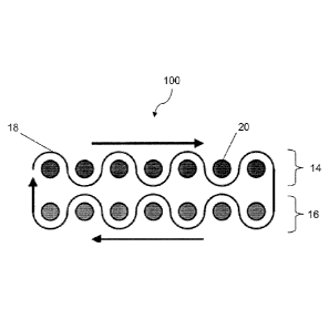
Turning now to the figures, Figure 3 illustrates a step involved in a method
for weaving a seamless preform 100, according to one exemplary embodiment of
the
present invention. The method involves weaving a seamless preform or
engineered tube
100, which is commonly referred to as a 'sock' in the fiber-reinforced
composites art.
The sock is woven flat, but opens into a desired three dimensional shape when
conformed
onto a mandrel having the desired dimensions.
The method according to this embodiment uses at least two layers 14, 16
of warp fiber or yarn 20 on the loom. Weft fiber or yarn 18 is typically
inserted using a
shuttle that continuously traverses along the width of the loom so the preform
will have a
closed edge, and therefore has continuous reinforcement in the hoop direction.
In such an
arrangement, when the shuttle moves in one direction, for example left to
right, weft fiber
or yarn 18 weaves with the warp fiber or yarn 20 in the top layer 14 and when
it moves
from right to left, it weaves with the warp fiber 20 in the bottom layer 16.
Since the weft
fiber or yarn 18 is coming off a shuttle, the fiber or yarn 18 weaving the top
14 and
bottom layers 16 are connected on the edges, as shown in Figure 3, for
example.
Using the tubular weaving technique described above, one exemplary
embodiment of the present invention is a method for weaving seamless fiber
preforms
120 that can be formed into complex axisymmetrie shapes (i.e. shapes with
rotational
symmetry about a central axis) that have one or more concentric segments, such
as that
shown in Figure 4(b), for example, which is a top-view of a seamless fiber
preform 120
woven using the instant tubular weaving technique. Figure 4(a) shows a cross-
sectional
view of the same structure along the imaginary line B-B depicting different
segments 'a'
through'? of the fiber prefoun 120. As it can be envisioned from Figures 4(a)
and 4(b),
segments 'a', 'c', and `g' of the preform are concentric, as are segments 'b',
'd', `e', and
T. Because Figure 4(b) is a top-view of the fiber preform 120, segments 'a',
'c', and `g'
cannot be seen in this figure as they are formed in a vertical plane or along
the z-axis of a
three-dimensional coordinate system. Although a preferred embodiment of the
woven
preform 120 is shown in Figures 4(a)-4(b), the present invention is not
restricted as such,
7
CA 02815074 2013-04-16
WO 2012/054731
PCT/US2011/057108
and it can practically use any variation of the tube weaving technique to
produce a
seamless preform that can be shaped into a structure with concentric segments.
Preform 120 can be woven by varying the number of warp fibers or yams
20 that actually weave into the preform 120 so that the length of each pair of
weft fibers
18 (that form an individual ring in the tube) varies along the length of the
preform 120.
This results in a tubular preform 120 that has a varying diameter along its
length, as
shown in Figure 5, for example. Figure 5, which is a top view of a flat woven
prefoini
120 on the loom, has a woven portion 110 wherein all warp yarns 20 are
interwoven with
weft yarn 18, and a partially woven portion 115 where only some of the warp
yarns 20
are woven with weft yarn 18 to form a tube of a smaller diameter when compared
to
woven portion 110. Edges of the preform are indicated by arrows 125, which are
practically seamless due to the fact that the shuttle carrying weft yam 18
continuously
traverses along the width of the loom while weaving the preform 120.
After the woven preform 120 is taken off the loom, it is trimmed along its
edges 125 to sever the unwoven portions of warp yarns 20 and to form a smooth
surface
on the outside of preform 120, resulting in a structure such as that shown in
Figure 7, for
example. It is then placed on a mandrel of a desired shape, and a first
portion 130 of the
preform having a larger diameter is folded onto a second portion 140 having a
smaller
diameter along the preform's central axis, as shown in Figure 6(a). Further, a
third
portion 150 having the smallest diameter can be folded inwardly to form a
folded preform
120, as shown in Figure 6(b), for example. It should be noted, however, that
the plurality
of warp yarns 20 are always running along the central axis of the preform, and
weft yarn
18 is always parallel to the hoop direction of the preform 120, thereby
providing
continuous hoop reinforcement.
These seamless preforms, as one can imagine, are engineered to form the
desired shape without forming wrinkles. This is a significant benefit over any
method
that may require darting and hand work to smooth the preform. In addition, the
resulting
structure has continuous reinforcement in the hoop direction, which improves
mechanical
strength of the entire structure.
The invention according to a further exemplary embodiment is a method
for weaving a seamless preform 200, as shown in Figure 9, for example. This
example
8
CA 02815074 2013-04-16
WO 2012/054731
PCT/US2011/057108
has a `11' shaped cross section, but it should be obvious that an is
possible by
eliminating one of the upstanding legs of the 'U'. The method uses the sock or
tube
weaving technique described in the above embodiments. However, the seamless
preform
200 in this case has two portions 230, 250 with constant diameters and a
transition
portion 240 where the preform goes from a smaller diameter portion 250 to
larger
diameter portion 230.
After the woven preform 200 is taken off the loom, it is trimmed along its
edges to sever the unwoven portions of warp yarns 20 and to form a smooth
surface on
the outside of preform 200. It is then placed on a mandrel of a desired shape,
in this case
a 'U.' shaped mandrel, and a first portion 230 of the prefoini having a larger
diameter is
folded onto a second portion 240 having a smaller diameter along the preform's
central
axis, as shown in Figure 10(a). Further, a third portion 250 having the
smallest diameter
can be folded inwardly to form a folded preform 200, as shown in Figure 10(b),
for
example. Forming folded portions in the preform is also referred to as putting
'cuffs' in
the preform. It should be noted, however, that the plurality of warp yarns 20
are always
running along the central axis of the preform, and weft yarn 18 is always
parallel to the
hoop direction of the seamless preform 200, thereby providing continuous hoop
reinforcement.
Defining the shape of this woven preform is facilitated by working in a
two-dimensional coordinate system that follows the curve defining the cross
section of
the desired structure. This is the "s" coordinate shown in Figure 5, for
example, where
the warp direction is indicated by an arrow along the x-axis, and the weft
direction is
along the y-axis of the coordinate system. This coordinate corresponds to the
location of
a pair of weft fibers in the warp direction. The required length of the weft
fiber at a
specific "s" location is defined by calculating the perimeter of the desired
structure at that
same location. In effect, this process unfolds and flattens the concentric
structure as
shown in Figure 5.
Since the seamless preform has been engineered to have the proper length
of weft fiber at each "s" location along the warp direction, it will take the
desired shape
without forming wrinkles. This is a significant benefit over methods that may
require
darting and hand work to smooth the preform. In addition, the resulting
structure has
9
CA 02815074 2013-04-16
WO 2012/054731
PCT/US2011/057108
continuous reinforcement in the hoop direction, which improves mechanical
strength of
the entire structure.
Although a single layered structure is described in the embodiments
disclosed herein, the present invention is not limited as such, and structures
or preforms
having a multilayer structure including more than two warp layers and more
than one
weft yarn can be produced by one skilled in the art without departing from the
spirit and
scope of the invention. The multilayered structure can also include one or
more layers of
a fabric formed on or attached to one or both surfaces of the tubular woven
structure.
The additional layer can be a lay-up, a flat woven, an endless woven, a
nonwoven, a
braided or a knitted structure.
Similarly, although structures having just two or three different diameters
are disclosed herein, the present invention is not limited as such, and
structures with
concentric segments having practically any number of diameters can be produced
using
the methods of the present invention.
The methods disclosed herein are applicable to practically any fiber that
can be machine woven, and practically any pattern can be used in the main body
of the
preform (i.e. plain weave, twill, satin, etc.). Similarly, the warp and/or
weft yarns used in
the present invention can be made of a material selected from the group
consisting of
glass, carbon, ceramic, aramid, polyethylene, polyester, polyamide and other
materials
which exhibit desired physical, thermal, chemical and/or other properties.
Through the
use of such reinforcement materials, which ultimately become a constituent
element of
the completed composite, the desired characteristics of the reinforcement
materials, such
as very high strength, are imparted to the completed composite component. The
warp
and/or weft yarns used in the present invention can be monofilaments,
multifilaments,
twisted multifilaments, plied multifilaments, untwisted tows, cabled, or
braided
structures.
After the desired reinforcement preform 120, 200 has been constructed,
matrix material may be introduced to and into the preform 120, 200 using resin
transfer
molding or chemical vapor infiltration so that typically the reinforcement
preform
becomes encased in the matrix material and matrix material fills the
interstitial areas
between the constituent elements of the reinforcement preform. The matrix
material may
CA 02815074 2013-04-16
WO 2012/054731
PCT/US2011/057108
be any of a wide variety of materials, such as epoxy, polyester, vinyl-ester,
ceramic,
carbon and/or other materials, which also exhibit desired physical, thermal,
chemical,
and/or other properties. The final structure may be cured using methods
commonly
known in the art, thus forming composites which can form a part of a window
frame, a
wheel rim, or a combustor in a jet engine, for example.
Although preferred embodiments of the present invention and
modifications thereof have been described in detail herein, it is to be
understood that this
invention is not limited to this precise embodiment and modifications, and
that other
modifications and variations may be effected by one skilled in the art without
departing
from the spirit and scope of the invention as defined by the appended claims.
11