Note: Descriptions are shown in the official language in which they were submitted.
CA 02815297 2013-05-08
LOW-PROFILE ROLLING SPRAY APPLICATOR
FIELD
[0001] The present disclosure relates to a spray applicator and more
particularly to a low-profile rolling spray applicator.
BACKGROUND
[0002] This section provides background information related to the
present
disclosure which is not necessarily prior art.
[0003] The use of a release agent on the surface of a press or mold cavity is
common to allow a workpiece to be removed from the press or mold cavity
without
sticking to the surface thereof. Accordingly, release agents are commonly
sprayed on
the surface using various sprayers and other techniques. A problem in the art
exists
when the size of the press surfaces are extremely large and in close proximity
to one
another even in a fully opened state. Accordingly, it is desirable to provide
a method
and device for applying a release agent to the surface of a large press that
requires the
application of the release agent on upper and lower surfaces thereof.
SUMMARY
[0004] This section provides a general summary of the disclosure, and is not
a comprehensive disclosure of its full scope or all of its features.
[0005] The present disclosure provides a low-profile rolling spray
applicator
that includes an elongated spray bar including a plurality of nozzles on upper
and lower
surfaces thereof with a fluid supply connected to the elongated spray bar. A
frame
1
CA 02815297 2013-05-08
=
supports the elongated spray bar and includes a plurality of wheels that
support the
frame as well as a handle attached to the frame to allow the rolling spray
applicator to
be rolled inside of a large press while the nozzles of the elongated spray bar
spray a
release agent or other fluid onto the upper and lower surfaces simultaneously
as the
spray applicator is rolled from one end of the press to another.
[0006] Further areas of applicability will become apparent from the
description
provided herein. The description and specific examples in this summary are
intended
for purposes of illustration only and are not intended to limit the scope of
the present
disclosure.
DRAWINGS
[0007] The drawings described herein are for illustrative purposes
only of
selected embodiments and not all possible implementations, and are not
intended to
limit the scope of the present disclosure.
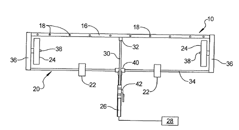
[0008] Figure 1 is a top plan view of the low-profile rolling spray
applicator
according to the principles of the present disclosure;
[0009] Figure 2 is a front plan view of the low-profile rolling spray
applicator
shown in Figure 1; and
[0010] Figure 3 is a schematic illustration of the spray pattern from
the
nozzles of the rolling spray applicator for applying a spray to an upper and
lower surface
simultaneously according to the principles of the present disclosure.
[0011] Corresponding reference numerals indicate corresponding parts
throughout the several views of the drawings.
2
CA 02815297 2013-05-08
,
DETAILED DESCRIPTION
[0012] Example embodiments will now be described more fully with
reference
to the accompanying drawings.
[0013] Example embodiments are provided so that this disclosure will
be
thorough, and will fully convey the scope to those who are skilled in the art.
Numerous
specific details are set forth such as examples of specific components,
devices, and
methods, to provide a thorough understanding of embodiments of the present
disclosure. It will be apparent to those skilled in the art that specific
details need not be
employed, that example embodiments may be embodied in many different forms and
that neither should be construed to limit the scope of the disclosure. In some
example
embodiments, well-known processes, well-known device structures, and well-
known
technologies are not described in detail.
[0014] The terminology used herein is for the purpose of describing particular
example embodiments only and is not intended to be limiting. As used herein,
the
singular forms "a," "an," and "the" may be intended to include the plural
forms as well,
unless the context clearly indicates otherwise. The terms "comprises,"
"comprising,"
"including," and "having," are inclusive and therefore specify the presence of
stated
features, integers, steps, operations, elements, and/or components, but do not
preclude
the presence or addition of one or more other features, integers, steps,
operations,
elements, components, and/or groups thereof. The method steps, processes, and
operations described herein are not to be construed as necessarily requiring
their
performance in the particular order discussed or illustrated, unless
specifically identified
3
CA 02815297 2013-05-08
as an order of performance. It is also to be understood that additional or
alternative
steps may be employed.
[0016] When an element or layer is referred to as being "on," "engaged
to,"
"connected to," or "coupled to" another element or layer, it may be directly
on, engaged,
connected or coupled to the other element or layer, or intervening elements or
layers
may be present. In contrast, when an element is referred to as being "directly
on,"
"directly engaged to," "directly connected to," or "directly coupled to"
another element or
layer, there may be no intervening elements or layers present. Other words
used to
describe the relationship between elements should be interpreted in a like
fashion (e.g.,
"between" versus "directly between," "adjacent" versus "directly adjacent,"
etc.). As
used herein, the term "and/or" includes any and all combinations of one or
more of the
associated listed items.
[0016] Although the terms first, second, third, etc. may be used
herein to
describe various elements, components, regions, layers and/or sections, these
elements, components, regions, layers and/or sections should not be limited by
these
terms. These terms may be only used to distinguish one element, component,
region,
layer or section from another region, layer or section. Terms such as "first,"
"second,"
and other numerical terms when used herein do not imply a sequence or order
unless
clearly indicated by the context. Thus, a first element, component, region,
layer or
section discussed below could be termed a second element, component, region,
layer
or section without departing from the teachings of the example embodiments.
[0017] Spatially relative terms, such as "inner," "outer," "beneath,"
"below,"
"lower," "above," "upper," and the like, may be used herein for ease of
description to
4
CA 02815297 2013-05-08
describe one element or feature's relationship to another element(s) or
feature(s) as
illustrated in the figures. Spatially relative terms may be intended to
encompass
different orientations of the device in use or operation in addition to the
orientation
depicted in the figures. For example, if the device in the figures is turned
over,
elements described as "below" or "beneath" other elements or features would
then be
oriented "above" the other elements or features. Thus, the example term
"below" can
encompass both an orientation of above and below. The device may be otherwise
oriented (rotated 90 or at other orientations) and the spatially relative
descriptors used
herein interpreted accordingly.
[0018]
With reference to Figures 1-3, the low-profile rolling spray applicator
according to the principles of the present disclosure will now be described.
The low-
profile rolling spray applicator 10 is designed to be utilized for spraying a
release agent
or other fluid such as a lubricant, coating, primer, paint, or other fluid
onto upper and
lower surfaces simultaneously within a press, mold, or other tightly
configured space
such as the upper and lower surfaces 12, 14, as illustrated in Figures 2 and
3.
[0019]
The low-profile rolling spray applicator 10 includes an elongated spray
bar 16 including a plurality of nozzles 18 disposed along the upper and lower
sides of
the spray bar 16. A frame 20 supports the elongated spray bar 16 and includes
a
plurality of wheels or other rollers 22, 24 supporting the frame 20. An
elongated handle
26 is attached to either or both of the elongated spray bar 16 and the frame
20. The
handle 26 can be made from plastic or metal and can be expandable/retractable.
A
fluid supply including a vessel 28 and hose 30 can be connected to the
elongated spray
bar 16 by a fitting 32. The vessel 28 can be pressurized or provided with a
pump and
5
CA 02815297 2014-08-26
can be filled with fluid release agent, lubricant, coating, primer, or paint,
by way of
example.
[0020] The frame 20 can include an axle 34 that supports one or more wheels
22 thereon and is rotatably supported at its ends by a pair of side struts 36
that are
connected between the axle 34 and the elongated spray bar 16. Additional
wheels 24
can be mounted to the side struts 36 by an axle shaft 38. It is noted that the
wheels 22,
24 can be the same or different sized and can have diameters ranging from less
than
one to several inches depending upon the opening of the specific press being
coated. It
should be understood that the frame can take on many forms and is designed to
support the spray bar 16 for rolling movement on wheels or rollers.
[0021] In the embodiments shown, the handle 26 is connected to the
axle 34
by a T-joint 40 and can be secured at a generally mid-location along the axle
by rail
fittings.
[0022] The low-profile rolling spray applicator 10 is designed to have
a low
profile such that a maximum height profile H of the rolling spray applicator
10 can be
defined by a height of the wheels 24 that are attached to the side struts 36,
or
alternatively, does not exceed two times a height h of the wheels 22. The
nozzles 18
are arranged along the upper and lower surfaces of the elongated spray bar 16
to
provide an overlapping spray pattern as illustrated in Figure 3 such that
adjacent upper
and lower spray nozzles 18 have a spray pattern that overlap with one another
to
provide a uniform coating. Thus, an even spray pattern over the upper and
lower
surfaces 12, 14 of a press, mold cavity, or other closely spaced opposing
surfaces can
be provided. It is intended that the spacing of the elongated spray bar 16 can
be
6
CA 02815297 2013-05-08
adjusted so that it is approximately located midway between the upper and
lower
surfaces 12, 14. Furthermore, the handle 26 is elongated, and can be
extendable/retractable so as to allow a greater range of travel between the
upper and
lower surfaces 12, 14. It is anticipated that surfaces that are 20 feet long
or longer can
be coated by the rolling spray applicator 10, according to the principles of
the present
disclosure.
[0023] In operation, the vessel 28 containing the release agent or
other fluid
to be applied to the surfaces 12, 14 can be pressurized or provided with a
pump and
one or more control valves 42 can be disposed along the hose or other conduit
30 and
can be opened to supply the pressurized fluid to each of the nozzles 18 along
the spray
bar 16. According to a test arrangement, sixteen spray nozzles having a
spraying angle
of 110 as well as four end nozzles having a spraying angle of approximately
800 were
threaded onto an elongated PVC spray bar although metal pipes could be used.
It
should be understood that more or fewer spray nozzles can be used depending
upon
the specific application. The nozzles can be used to apply several gallons per
minute of
release agent to each surface 12, 14, simultaneously in a single application.
The
release agent can be applied in close proximity to the surfaces while reaching
and
evenly coating places on the surfaces 12, 14 with very little effort and time
in
comparison to standard means.
[0024] It is noted that the wheels 22, 24 can be made from glass-
filled nylon
that can resist temperatures of up to 425 F. It is noted that the size of the
components
of the rolling spray applicator can be dependent upon the specific desired
application.
In the tested embodiment, the elongated spray bar was approximately five feet
long and
7
CA 02815297 2013-05-08
=
% inch in diameter and the side struts 36 were made from 1 5/8 inch square
strut
channeling. The length of the spray bar may range from less than three to
greater than
ten feet to facilitate coverage of the size range of press platens known to
date.
[0025]
The low-profile rolling spray applicator 10 allows a very uniform coating
to be applied to both top and bottom platens 12, 14 in a press with limited
accessibility,
and it can be accomplished efficiently without a lot of setup, labor, or time
required to do
it.
[0026] The foregoing description of the embodiments has been provided for
purposes of illustration and description. It is not intended to be exhaustive
or to limit the
disclosure. Individual elements or features of a particular embodiment are
generally not
limited to that particular embodiment, but, where applicable, are
interchangeable and
can be used in a selected embodiment, even if not specifically shown or
described. The
same may also be varied in many ways. Such variations are not to be regarded
as a
departure from the disclosure, and all such modifications are intended to be
included
within the scope of the disclosure.
8