Note: Descriptions are shown in the official language in which they were submitted.
CA 02815298 2013-04-19
WO 2013/005047 1
PCT/GB2012/051592
HEATED CHROMATOGRAPHIC SEPARATION PROCESS
The present invention relates to an improved chromatographic separation
process for
purifying polyunsaturated fatty acids (PUFAs) and derivatives thereof. In
particular,
the present invention relates to an improved chromatographic separation
process
which allows a reduced amount of eluent to be used.
Fatty acids, in particular PUFAs, and their derivatives are precursors for
biologically
important molecules, which play an important role in the regulation of
biological
functions such as platelet aggregation, inflammation and immunological
responses.
Thus, PUFAs and their derivatives may be therapeutically useful in treating a
wide
range of pathological conditions including CNS conditions; neuropathies,
including
diabetic neuropathy; cardiovascular diseases; general immune system and
inflammatory conditions, including inflammatory skin diseases.
PUFAs are found in natural raw materials, such as vegetable oils and marine
oils.
Such PUFAs are, however, frequently present in such oils in admixture with
saturated
fatty acids and numerous other impurities. PUFAs should therefore desirably be
purified before nutritional or pharmaceutical uses.
Unfortunately, PUFAs are extremely fragile. Thus, when heated in the presence
of
oxygen, they are prone to isomerization, peroxidation and oligomerization. The
fractionation and purification of PUFA products to prepare pure fatty acids is
therefore difficult. Distillation, even under vacuum, can lead to non-
acceptable
product degradation.
Chromatographic separation techniques are well known to those of skill in the
art.
Chromatographic separation techniques involving stationary bed systems and
simulated or actual moving bed systems are both familiar to one of skill in
the art.
In a conventional stationary bed chromatographic system, a mixture whose
components are to be separated percolates through a container. The container
is
generally cylindrical, and is typically referred to as the column. The column
contains
a packing of a porous material (generally called the stationary phase)
exhibiting a high
permeability to fluids. The percolation velocity of each component of the
mixture
CA 02815298 2013-04-19
WO 2013/005047 2
PCT/GB2012/051592
depends on the physical properties of that component so that the components
exit
from the column successively and selectively. Thus, some of the components
tend to
fix strongly to the stationary phase and thus will percolate slowly, whereas
others tend
to fix weakly and exit from the column more quickly. Many different stationary
bed
chromatographic systems have been proposed and are used for both analytical
and
industrial production purposes.
Simulated and actual moving bed chromatography are known techniques, familiar
to
those of skill in the art. The principle of operation involves countercurrent
movement
of a liquid eluent phase and a solid adsorbent phase. This operation allows
minimal
usage of solvent making the process economically viable. Such separation
technology
has found several applications in diverse areas, including hydrocarbons,
industrial
chemicals, oils, sugars and APIs.
Thus, a simulated moving bed chromatography apparatus consists of a number of
individual columns containing adsorbent which are connected together in
series.
Eluent is passed through the columns in a first direction. The injection
points of the
feedstock and the eluent, and the separated component collection points in the
system,
are periodically shifted by means of a series of valves. The overall effect is
to
simulate the operation of a single column containing a moving bed of the solid
adsorbent, the solid adsorbent moving in a countercurrent direction to the
flow of
eluent. Thus, a simulated moving bed system consists of columns which, as in a
conventional stationary bed system, contain stationary beds of solid adsorbent
through
which eluent is passed, but in a simulated moving bed system the operation is
such as
to simulate a continuous countercurrent moving bed.
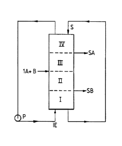
A typical simulated moving bed chromatography apparatus is illustrated with
reference to Figure 1. The concept of a simulated or actual moving bed
chromatographic separation process is explained by considering a vertical
chromatographic column containing stationary phase S divided into sections,
more
precisely into four superimposed sub-zones I, II, III and IV going from the
bottom to
the top of the column. The eluent is introduced at the bottom at IE by means
of a
pump P. The mixture of the components A and B which are to be separated is
introduced at IA + B between sub-zone II and sub-zone III. An extract
containing
CA 02815298 2014-08-25
3
mainly B is collected at SB between sub-zone I and sub-zone II, and a
raffinate
containing mainly A is collected at SA between sub-zone III and sub-zone IV.
In the case of a simulated moving bed system, a simulated downward movement of
the stationary phase S is caused by movement of the introduction and
collection points
relative to the solid phase. In the case of an actual moving bed system,
simulated
downward movement of the stationary phase S is caused by movement of the
various
chromatographic columns relative to the introduction and collection points. In
Figure
1, eluent flows upward and mixture A + B is injected between sub-zone II and
sub-
zone III. The components will move according to their chromatographic
interactions
with the stationary phase, for example adsorption on a porous medium. The
component B that exhibits stronger affinity to the stationary phase (the
slower running
component) will be more slowly entrained by the eluent and will follow it with
delay.
The component A that exhibits the weaker affinity to the stationary phase (the
faster
running component) will be easily entrained by the eluent. If the right set of
parameters, especially the flow rate in each sub-zone, are correctly estimated
and
controlled, the component A exhibiting the weaker affinity to the stationary
phase will
be collected between sub-zone III and sub-zone IV as a raffinate and the
component B
exhibiting the stronger affinity to the stationary phase will be collected
between sub-
zone I and sub-zone II as an extract.
It will therefore be appreciated that the conventional simulated moving bed
system
schematically illustrated in Fig. 1 is limited to binary fractionation.
Processes and equipment for simulated moving bed chromatography are described
in
several patents, including US 2,985,589, US 3,696,107, US 3,706,812, US
3,761,533,
FR-A-2103302, FR-A-2651148 and FR-A-2651149. The topic is also dealt with at
length in "Preparative and Production Scale Chromatography", edited by
Ganetsos
and Barker, Marcel Dekker Inc, New York, 1993.
An actual moving bed system is similar in operation to a simulated moving bed
system. However, rather than shifting the injection points of the feed mixture
and the
eluent, and the separated component collection points by means of a system of
valves,
CA 02815298 2014-08-25
4
instead a series of adsorption units (i.e. columns) arc physically moved
relative to the
feed and drawoff points. Again, operation is such as to simulate a continuous
countercurrent moving bed.
Processes and equipment for actual moving bed chromatography are described in
several patents, including US 6,979,402, US 5,069,883 and US 4,764,276.
Purification of PUFA products is particularly challenging. Thus, many suitable
feedstocks for preparing PUFA products are extremely complex mixtures
containing a
large number of different components with very similar retention times in
chromatography apparatuses. It is therefore very difficult to separate
therapeutically
useful PUFAs from such feedstocks. However, a high degree of purity of PUFA
products is required, particularly for pharmaceutical and nutraceutical
applications.
Historically, therefore, distillation has been used when high purity PUFA
products are
required. There are, however, significant drawbacks to using distillation as a
separation technique for delicate PUFAs as discussed above.
In general, all chromatographic separation techniques for separating PUFAs
utilise
large volumes of organic solvents as eluents. After the chromatographic
separation
process is completed the PUFAs must be recovered from solution in the eluent.
Typically a large expenditure of time and energy is involved in recovering
PUFAs
from solution in the eluent. Furthermore, organic solvents used as eluents in
chromatographic separation processes are frequently harmful to the environment
or to
the operatives handling them. Therefore, a chromatographic separation process
which
reduces the amount of organic solvent that needs to be used is required.
As discussed above, suitable commercial feedstocks, for example fish oils,
containing
PUFAs typically contain a large number of different components with very
similar
retention times in chromatography apparatuses. There is therefore also a
requirement
for a chromatographic separation process which improves the resolution between
components of a feed mixture having similar retention times.
CA 02815298 2013-04-19
WO 2013/005047 5
PCT/GB2012/051592
Summary of the invention
It has advantageously been found that a chromatographic separation process
carried
out at a temperature above room temperature requires less organic solvent
eluent.
Thus, at elevated temperatures, retention times for many PUFAs of commercial
interest are substantially reduced, which in turn means that less organic
solvent eluent
must be used to separate a mixture containing a variety of different PUFAs,
for
example a fish oil feedstock, or a feedstock derived from fish oils.
It has also advantageously been found that increasing the amount of water used
in a
chromatographic separation process utilising an aqueous organic solvent
improves the
resolution of components present in feed mixtures having similar retention
times.
This means that an eluent having a higher water content allows a cleaner
separation of
a PUFA product from a feed mixture.
The present invention therefore provides a chromatographic separation process
for
recovering a polyunsaturated fatty acid (PUFA) product from a feed mixture,
which
process comprises passing the feed mixture through one or more chromatographic
columns containing, as eluent, an aqueous organic solvent,
wherein the temperature of at least one of the chromatographic columns through
which the feed mixture is passed is greater than room temperature.
Description of the Figures
Figure 1 illustrates the basic principles of a simulated or actual moving bed
process
for separating a binary mixture.
Figure 2 illustrates one particular embodiment of the invention which is
suitable for
separating EPA from faster and slower running components (i.e. more polar and
less
polar impurities).
Figure 3 illustrates one particular embodiment of the invention which is
suitable for
separating DHA from faster and slower running components (i.e. more polar and
less
polar impurities).
CA 02815298 2013-04-19
WO 2013/005047 6
PCT/GB2012/051592
Figure 4 illustrates in more detail one particular embodiment of the invention
which is
suitable for separating EPA from faster and slower running components (i.e.
more
polar and less polar impurities).
Figure 5 illustrates in more detail one particular embodiment of the invention
which is
suitable for separating DHA from faster and slower running components (i.e.
more
polar and less polar impurities).
Figure 6 illustrates in more detail an alternative method for the first
preferred
embodiment of the invention which is suitable for separating EPA from faster
and
slower running components (i.e. more polar and less polar impurities).
Figure 7 illustrates in more detail an alternative method for the second
preferred
embodiment of the invention which is suitable for separating DHA from faster
and
slower running components (i.e. more polar and less polar impurities).
Figure 8 illustrates one particular embodiment of the invention for purifying
EPA
from faster and slower running components (i.e. more polar and less polar
impurities).
Figure 9 illustrates an alternative method for one particular embodiment of
the
invention for purifying EPA from faster and slower running components (i.e.
more
polar and less polar impurities).
Figure 10 illustrates three ways in which one particular embodiment of the
chromatographic separation process of the invention may be carried out.
Figure 11 shows a further embodiment for purifying EPA from faster and slower
running components (i.e. more polar and less polar impurities).
Figure 12 shows a GC FAMES trace of an EPA PUFA product produced in
accordance with the present invention.
Figure 13 shows a GC FAMES trace of an EPA PUFA product produced in
accordance with the present invention.
CA 02815298 2013-04-19
WO 2013/005047 7
PCT/GB2012/051592
Detailed description of the invention
As used herein, the term "PUFA product" refers to a product comprising one or
more
polyunsaturated fatty acids (PUFAs), and/or derivatives thereof, typically of
nutritional or pharmaceutical significance. Typically, the PUFA product is a
single
PUFA or derivative thereof. Alternatively, the PUFA product is a mixture of
two or
more PUFAs or derivatives thereof, for example two.
The term "polyunsaturated fatty acid" (PUFA) refers to fatty acids that
contain more
than one double bond. Such PUFAs are well known to the person skilled in the
art.
As used herein, a PUFA derivative is a PUFA in the form of a mono-, di- or tri-
glyceride, ester, phospho lipid, amide, lactone, or salt. Triglycerides and
esters are
preferred. Esters are more preferred. Esters are typically alkyl esters,
preferably C1 -
C6 alkyl esters, more preferably C1-C4 alkyl esters. Examples of esters
include methyl
and ethyl esters. Ethyl esters are most preferred.
Typically, the PUFA product comprises at least one co-3 or co-6 PUFA,
preferably at
least one co-3 PUFA. Examples of co-3 PUFAs include alpha-linolenic acid
(ALA),
stearidonic acid (SDA), eicosatrienoic acid (ETE), eicosatetraenoic acid
(ETA),
eicosapentaenoic acid (EPA), docosapentaenoic acid (DPA) and docosahexaenoic
acid (DHA). SDA, EPA, DPA and DHA are preferred. EPA and DHA are more
preferred. Examples of co-6 PUFAs include linoleic acid (LA), gamma-linolenic
acid
(GLA), eicosadienoic acid, dihomo-gamma-linolenic acid (DGLA), arachidonic
acid
(ARA), docosadienoic acid, adrenic acid and docosapentaenoic (o)-6) acid. LA,
ARA,
GLA and DGLA are preferred.
In one embodiment, the PUFA product is EPA and/or EPA ethyl ester (EE)
In another embodiment, the PUFA product is DHA and/or DHA ethyl ester (EE).
In a yet further embodiment, the PUFA product is a mixture of EPA and DHA
and/or
EPA EE and DHA EE.
CA 02815298 2013-04-19
WO 2013/005047 8
PCT/GB2012/051592
In a most preferred embodiment, the PUFA product is EPA or EPA ethyl ester
which
is produced in greater than 90% purity, preferably greater than 95% purity,
and more
preferably greater than 97% purity.
Typically, in addition to said PUFA product, an additional secondary PUFA
product
is collected in the chromatographic separation process of the invention.
Preferably,
the PUFA product is EPA and the additional secondary PUFA product is DHA.
In a further embodiment of the invention, the apparatus is configured to
collect a
PUFA product which is a concentrated mixture of EPA and DHA. Thus, a feed
mixture is used which contains EPA, DHA, components which are more polar than
EPA and DHA, and components which are less polar than EPA and DHA. In the
first
separation step, less polar material than EPA and DHA is typically removed. In
the
second separation step, material which is more polar than EPA and DHA is
typically
removed, and a concentrated mixture of EPA and DHA is collected as the PUFA
product.
Suitable feed mixtures for fractionating by the process of the present
invention may be
obtained from natural sources including vegetable and animal oils and fats,
and from
synthetic sources including oils obtained from genetically modified plants,
animals
and micro organisms including yeasts. Examples include fish oils, algal and
microalgal oils and plant oils, for example borage oil, Echium oil and evening
primrose oil. In one embodiment, the feed mixture is a fish oil. In another
embodiment, the feed mixture is an algal oil. Algal oils are particularly
suitable when
the desired PUFA product is EPA and/or DHA. Genetically modified Safflower oil
is
particularly suitable when the desired PUFA product is GLA. Genetically
modified
yeast is particularly suitable when the desired PUFA product is EPA.
In a particularly preferred embodiment the feed mixture is a fish oil or fish-
oil derived
feedstock. It has advantageously been found that when a fish-oil or fish-oil
derived
feed stock is used, an EPA or EPA ethyl ester PUFA product can be produced by
the
process of the present invention in greater than 90% purity, preferably
greater than
95% purity, and more preferably greater than 97% purity.
CA 02815298 2013-04-19
WO 2013/005047 9
PCT/GB2012/051592
The feed mixture may undergo chemical treatment before fractionation by the
process
of the invention. For example, it may undergo glyceride transesterification or
glyceride hydrolysis followed in certain cases by selective processes such as
crystallisation, molecular distillation, urea fractionation, extraction with
silver nitrate
or other metal salt solutions, iodolactonisation or supercritical fluid
fractionation.
Alternatively, a feed mixture may be used directly with no initial treatment
step.
The feed mixtures typically contain the PUFA product and at least one more
polar
component and at least one less polar component. The less polar components
have a
stronger adherence to the adsorbent used in the process of the present
invention than
does the PUFA product. During operation, such less polar components typically
move with the solid adsorbent phase in preference to the liquid eluent phase.
The
more polar components have a weaker adherence to the adsorbent used in the
process
of the present invention than does the PUFA product. During operation, such
more
polar components typically move with the liquid eluent phase in preference to
the
solid adsorbent phase. In general, more polar components will be separated
into a
raffinate stream, and less polar components will be separated into an extract
stream.
Examples of the more and less polar components include (1) other compounds
occurring in natural oils (e.g. marine oils or vegetable oils), (2) byproducts
formed
during storage, refining and previous concentration steps and (3) contaminants
from
solvents or reagents which are utilized during previous concentration or
purification
steps.
Examples of (1) include other unwanted PUFAs; saturated fatty acids; sterols,
for
example cholesterol; vitamins; and environmental pollutants, such as
polychlorobiphenyl (PCB), polyaromatic hydrocarbon (PAH) pesticides,
chlorinated
pesticides, dioxines and heavy metals. PCB, PAH, dioxines and chlorinated
pesticides are all highly non-polar components.
Examples of (2) include isomers and oxidation or decomposition products from
the
PUFA product, for instance, auto-oxidation polymeric products of fatty acids
or their
derivatives.
CA 02815298 2013-04-19
WO 2013/005047 10
PCT/GB2012/051592
Examples of (3) include urea which may be added to remove saturated or mono-
unsaturated fatty acids from the feed mixture.
Preferably, the feed mixture is a PUFA-containing marine oil (e.g. a fish
oil), more
preferably a marine oil (e.g. a fish oil) comprising EPA and/or DHA.
A typical feed mixture for preparing concentrated EPA (EE) by the process of
the
present invention comprises 50-75% EPA (EE), 0 to 10% DHA (EE), and other
components including other essential o)-3 and o)-6 fatty acids.
A preferred feed mixture for preparing concentrated EPA (EE) by the process of
the
present invention comprises 55% EPA (EE), 5% DHA (EE), and other components
including other essential o)-3 and o)-6 fatty acids. DHA (EE) is less polar
than
EPA(EE).
A typical feed mixture for preparing concentrated DHA (EE) by the process of
the
present invention comprises 50-75% DHA (EE), 0 to 10% EPA (EE), and other
components including other essential o)-3 and o)-6 fatty acids.
A preferred feed mixture for preparing concentrated DHA (EE) by the process of
the
present invention comprises 75% DHA (EE), 7% EPA (EE) and other components
including other essential o)-3 and o)-6 fatty acids. EPA (EE) is more polar
than DHA
(EE).
A typical feed mixture for preparing a concentrated mixture of EPA (EE) and
DHA
(EE) by the process of the present invention comprises greater than 33% EPA
(EE),
and greater than 22% DHA (EE).
Typically, the temperature of all of the chromatographic columns used in the
process
of the present invention is greater than room temperature.
As will be appreciated, in the at least one chromatographic column which is at
a
temperature greater than room temperature, it is the interior of the column
which is
important to the separation process. Thus, it is typically the aqueous organic
solvent
CA 02815298 2013-04-19
WO 2013/005047 11
PCT/GB2012/051592
eluent and adsorbent inside the chromatographic column which is at the
temperature
greater than room temperature. It is, of course, possible to achieve the
required
temperature inside the at least one chromatographic column by internal (for
example
by heating the eluent and/or feed mixture) and/or external means (for example
by
heating the outside of the chromatographic column by any known conventional
means).
Typically, the required elevated temperature of the heated chromatographic
columns
is achieved by heating the aqueous organic solvent eluent and/or feed mixture.
This
has the effect of heating the columns internally.
Thus, the temperature of at least one of the chromatographic columns through
which
the feed mixture is passed can also be measured as the temperature of the
aqueous
organic solvent eluent.
Thus, the present invention also provides a chromatographic separation process
for
recovering a polyunsaturated fatty acid (PUFA) product from a feed mixture,
which
process comprises passing the feed mixture through one or more chromatographic
columns containing, as eluent, an aqueous organic solvent,
wherein the temperature of the eluent is greater than room temperature, as
defined
herein.
Alternatively, the required temperature of at least one of the chromatographic
columns is achieved by heating the columns. The heating may be carried out
using,
for example, an electric heating mantle, a heated water jacket or coil or by
radiative
heat lamps. The interior and/or exterior of the one or more chromatographic
columns
is typically heated.
The required temperature of at least one of the chromatographic columns may be
achieved by heating the columns and/or the aqueous organic solvent eluent,
and/or the
feed mixture.
Typically, the temperature of at least one of the chromatographic columns is
greater
than 30 C, preferably greater than 35 C, more preferably greater than 40 C,
even
more preferably greater than 45 C, even more preferably greater than 50 C,
even
CA 02815298 2013-04-19
WO 2013/005047 12
PCT/GB2012/051592
more preferably greater than 55 C, and even more preferably greater than 57 C.
A
temperature of 56 C is useful in certain embodiments.
Typically, the temperature of at least one of the chromatographic columns is
up to
100 C, preferably up to 95 C, more preferably up to 90 C, even more preferably
up to
85 C, even more preferably up to 80 C, even more preferably up to 75 C, and
even
more preferably up to 70 C.
Thus, typical temperature ranges for at least one of the chromatographic
columns are
from 30 to 100 C, from 35 to 95 C, from 40 to 90 C, from 45 to 85 C, from 50
to
80 C, from 55 to 75 C or from 57 to 70 C.
Preferred temperature ranges for at least one of the chromatographic columns
are
from 40 to 70 C, preferably from 50 to 67 C, more preferably from 56 to 65 C,
even
more preferably from 57 to 63 C.
The process of the present invention involves passing a feed mixture through
one or
more chromatographic columns. Any known chromatographic columns may be used
in the claimed process.
The one or more chromatographic columns typically contains an adsorbent.
Conventional adsorbents known in the art for chromatographic separation
techniques
may be used in the process of the present invention. When more than one
chromatographic column is used, each chromatographic column may contain the
same
or a different adsorbent. Typically, when more than one chromatographic column
is
used each column contains the same adsorbent. Examples of such commonly used
materials are polymeric beads, preferably polystyrene reticulated with DVB
(divinylbenzene); and silica gel, preferably reverse phase bonded silica gel
with C8 or
C18 alkanes, especially C18. C18 bonded reverse phase silica gel is preferred.
The
adsorbent used in the process of the present invention is preferably non-
polar.
The shape of the adsorbent stationary phase material may be, for example,
spherical
or nonspherical beads, preferably substantially spherical beads. Such beads
typically
have a diameter of 5 to 500 microns, preferably 10 to 500 microns, more
preferably
15 to 500 microns, more preferably 40 to 500 microns, more preferably 100 to
500
CA 02815298 2013-04-19
WO 2013/005047 13
PCT/GB2012/051592
microns, more preferably 250 to 500 microns, even more preferably 250 to 400
microns, most preferably 250 to 350 microns. In some embodiments, beads with a
diameter of 5 to 35 microns may be used, typically 10 to 30 microns,
preferably 15 to
25 microns. Some preferred particle sizes are somewhat larger than particle
sizes of
beads used in the past in simulated and actual moving bed processes. Use of
larger
particles enables a lower pressure of eluent to be used in the system. This,
in turn, has
advantages in terms of cost savings, efficiency and lifetime of the apparatus.
It has
surprisingly been found that adsorbent beads of large particle size may be
used in the
process of the present invention (with their associated advantages) without
any loss in
resolution.
The dimensions of the columns used are not particularly limited, and will
depend to
some extent on the volume of feed mixture to be purified. A skilled person
would
easily be able to determine appropriately sized columns to use. The diameter
of each
column is typically between 10 and 1000mm, preferably between 10 and 500mm,
more preferably between 25 and 250mm, even more preferably between 50 and 100
mm, and most preferably between 70 and 80 mm. The length of each column is
typically between 10 and 300 cm, preferably between 10 and 200 cm, more
preferably
between 25 and 150cm, even more preferably between 70 and 110 cm, and most
preferably between 80 and 100 cm.
The eluent used in the process of the present invention is an aqueous organic
solvent.
The aqueous organic solvent typically comprises water and one or more
alcohols,
ethers, esters, ketones or nitriles, or mixtures thereof.
Alcohol solvents are well known to the person skilled in the art. Alcohols are
typically short chain alcohols. Alcohols typically are of formula ROH, wherein
R is a
straight or branched Cl-C6 alkyl group. The C1-C6 alkyl group is preferably
unsubstituted. Examples of alcohols include methanol, ethanol, n-propanol, i-
propanol, n-butanol, i-butanol, s-butanol and t-butanol. Methanol and ethanol
are
preferred. Methanol is more preferred.
Ether solvents are well known to the person skilled in the art. Ethers are
typically
short chain ethers. Ethers typically are of formula R-O-R', wherein R and R'
are the
CA 02815298 2013-04-19
WO 2013/005047 14
PCT/GB2012/051592
same or different and represent a straight or branched Ci-C6 alkyl group. The
Ci-C6
alkyl group is preferably unsubstituted. Preferred ethers include
diethylether,
diisopropylether, and methyl t-butyl ether (MTBE).
Ester solvents are well known to the person skilled in the art. Esters are
typically
short chain esters. Esters typically are of formula R-(C=0)0-R', wherein R and
R' are
the same or different and represent a straight or branched C1-C6 alkyl group.
Preferred esters include methylacetate and ethylacetate.
Ketone solvents are well known to the person skilled in the art. Ketones are
typically
short chain ketones. Ketones typically are of formula R-(C=0)-R', wherein R
and R'
are the same or different and represent a straight or branched Ci-C6 alkyl
group. The
C1-C6 alkyl group is preferably unsubstituted. Preferred ketones include
acetone,
methylethylketone and methyl isobutyl ketone (MIBK).
Nitrile solvents are well known to the person skilled in the art. Nitriles are
typically
short chain nitriles. Nitriles typically are of formula R-CN, wherein R
represents a
straight or branched Ci-C6 alkyl group. The C1-C6 alkyl group is preferably
unsubstituted. Preferred nitriles include acetonitrile.
Typically, the aqueous organic solvent is aqueous alcohol or aqueous
acetonitrile.
The aqueous organic solvent is preferably aqueous methanol or aqueous
acetonitrile.
Aqueous methanol is more preferred.
Typically, the eluent is not in a supercritical state. Typically, the eluent
is a liquid.
Typically, the average water:organic solvent ratio, for example water:methanol
ratio,
of the eluent in the entire apparatus is from 0.1:99.9 to 12:88 parts by
volume,
preferably from 0.25:99.75 to 10:90 parts by volume, and more preferably from
0.5:99.5 to 9:91 parts by volume. In some embodiments the average
water:organic
solvent ratio, for example water:methanol ratio, of the eluent in the entire
apparatus is
preferably from 0.1:99.9 to 9:91 parts by volume, more preferably from
0.25:99.75 to
7:93 parts by volume, even more preferably from 0.5:99.5 to 6:94 parts by
volume. In
other embodiments, the average water:organic solvent ratio, for example
CA 02815298 2013-04-19
WO 2013/005047 15
PCT/GB2012/051592
water:methanol ratio, of the eluent in the entire apparatus is preferably from
4:96 to
12:88 parts by volume, preferably from 6:94 to 10:90 parts by volume, more
preferably from 7:93 to 9:91 parts by volume, and even more preferably from
7.5:92.5
to 8.5:91.5 parts by volume.
When the aqueous organic solvent is aqueous acetonitrile, the eluent typically
contains up to 30 wt% water, remainder acetonitrile. Preferably, the eluent
contains
from 5 to 25 wt% water, remainder acetonitrile. More preferably, the eluent
contains
from 10 to 20 wt% water, remainder acetonitrile. Even more preferably, the
eluent
contains from 15 to 25 wt% water, remainder acetonitrile.
Typically, the eluent contains 5 wt% water or greater, based on the total
weight of the
water and organic solvent. Preferably, the eluent contains 6 wt% water or
greater,
more preferably 7 wt% water or greater, even more preferably about 8 wt%
water.
Thus, the eluent typically contains from 5 to 15 wt% water, preferably from 6
to 13
wt% water, more preferably from 7 to 11 wt% water, even more preferably from
7.5
to 9.5 wt% water, even more preferably from 7.5 to 8.5 wt% water.
Advantageously,
this increased water content improves the resolution of closely related
components
present in the feed mixture. An increased water content of the eluent can
under
certain circumstances necessitate a larger volume of eluent being used. In
practice,
this is offset by heating at least one of the chromatographic columns through
which
the feed mixture is passed to a temperature greater than room temperature,
preferably
by heating the eluent to a temperature greater than room temperature. Heating
the
column and/or eluent in this way reduces the amount of solvent which needs to
be
used.
Any known chromatography apparatus may be used for the purposes of the process
of
the present invention, as long as it involves passing a feed mixture through
one or
more chromatographic columns containing, as eluent, an aqueous organic
solvent,
wherein the temperature of at least one of the chromatographic columns through
which the feed mixture is passed is greater than room temperature.
Each separation step of the process of the present invention is carried out in
a
simulated or actual moving bed chromatography apparatus.
CA 02815298 2013-04-19
WO 2013/005047 16
PCT/GB2012/051592
The number of chromatographic columns used in the process of the present
invention
is not particularly limited. In certain embodiments a single chromatographic
column
may be used. Thus, such embodiments typically involve a single stationary
column.
In other embodiments, more than one chromatographic column is used. This may
involve passing the feed mixture through two or more chromatographic columns,
which may be the same or different, arranged in series or in parallel. The
number of
columns used in this embodiment is not particularly limited, but typically
does not
exceed thirty columns.
One particular embodiment where multiple chromatographic columns are used is
simulated or actual moving bed chromatography.
Thus, the process of the present invention typically comprises introducing the
feed
mixture into one or more simulated or actual moving bed chromatography
apparatuses
having a plurality of linked chromatography columns containing, as eluent, an
aqueous organic solvent, wherein the temperature of at least one of the
plurality of
linked chromatographic columns is greater than room temperature.
Typically, the temperature of substantially all of the linked chromatographic
columns
is greater than room temperature. Preferably, the temperature of all of the
linked
chromatographic columns is greater than room temperature.
Any known simulated or actual moving bed chromatography apparatus may be
utilised for the purposes of the method of the present invention, as long as
the
apparatus is used in accordance with the process of the present invention.
Those
apparatuses described in US 2,985,589, US 3,696,107, US 3,706,812, US
3,761,533,
FR-A-2103302, FR-A-2651148, FR-A-2651149, US 6,979,402, US 5,069,883 and US
4,764,276 may all be used if configured in accordance with the process of the
present
invention.
In one embodiment, the process comprises the steps of:
(i) purifying the feed mixture in a first separation step in a simulated or
actual moving
bed chromatography apparatus having a plurality of linked chromatography
columns
CA 02815298 2013-04-19
WO 2013/005047 17
PCT/GB2012/051592
containing, as eluent, an aqueous organic solvent, to obtain an intermediate
product;
and
(ii) purifying the intermediate product obtained in (i) in a second separation
step using
a simulated or actual moving bed chromatography apparatus having a plurality
of
linked chromatography columns containing, as eluent, an aqueous organic
solvent, to
obtain the PUFA product;
wherein the temperature of one or more of the plurality of linked
chromatography
columns in the first separation step and/or one or more of the plurality of
linked
chromatography columns in the second separation step is greater than room
temperature; and wherein
(a) the first and second separation steps are carried out sequentially on the
same
chromatography apparatus, the intermediate product being recovered between the
first
and second separation steps and the process conditions in the chromatography
apparatus being adjusted between the first and second separation steps such
that the
PUFA product is separated from different components of the feed mixture in
each
separation step; or
(b) the first and second separation steps are carried out on separate first
and second
chromatography apparatuses respectively, the intermediate product obtained
from the
first separation step being introduced into the second chromatography
apparatus, and
the PUFA product being separated from different components of the feed mixture
in
each separation step.
In this embodiment, the term "simulated or actual moving bed chromatography
apparatus" typically refers to a plurality of linked chromatography columns
containing, as eluent, an aqueous organic solvent, and having one or more
injection
points for a feed mixture stream, one or more injection points for water
and/or organic
solvent, a raffinate take-off stream from which liquid can be collected from
said
plurality of linked chromatography columns, and an extract take-off stream
from
which liquid can be collected from said plurality of linked chromatography
columns.
The chromatography apparatus used in this embodiment has a single array of
chromatography columns linked in series containing, as eluent, an aqueous
organic
solvent. Typically, each of the chromatography columns are linked to the two
columns in the apparatus adjacent to that column. Thus, the output from a
given
column in the array is connected to the input of the adjacent column in the
array,
CA 02815298 2013-04-19
WO 2013/005047 18
PCT/GB2012/051592
which is downstream with respect to the flow of eluent in the array. Thus,
eluent can
flow around the array of linked chromatography columns. Typically, none of the
chromatography columns are linked to non-adjacent columns in the apparatus.
As used herein, the term "nonadjacent" refers to columns, in for example the
same
apparatus, separated by one or more columns, preferably 3 or more columns,
more
preferably 5 or more columns, most preferably about 5 columns.
Typically in this embodiment, each apparatus has only one injection point for
a feed
mixture. In one embodiment, each apparatus has only one injection point for
the
aqueous organic solvent eluent. In another embodiment, each apparatus has two
or
more injection points for water and/or organic solvent.
The term "raffinate" is well known to the person skilled in the art. In the
context of
actual and simulated moving bed chromatography it refers to the stream of
components that move more rapidly with the liquid eluent phase compared with
the
solid adsorbent phase. Thus, a raffinate stream is typically enriched with
more polar
components, and depleted of less polar components compared with a feed stream.
The term "extract" is well known to the person skilled in the art. In the
context of
actual and simulated moving bed chromatography it refers to the stream of
components that move more rapidly with the solid adsorbent phase compared with
the
liquid eluent phase. Thus, an extract stream is typically enriched with less
polar
components, and depleted of more polar components compared with a feed stream.
The number of columns used in each apparatus in this embodiment is not
particularly
limited. A skilled person would easily be able to determine an appropriate
number of
columns to use. The number of columns is typically 4 or more, preferably 6 or
more,
more preferably 8 or more, for example 4, 5, 6, 7, 8, 9, or 10 columns. In
preferred
embodiment, 5 or 6 columns, more preferably 6 columns. are used. In another
preferred embodiment, 7 or 8 columns, more preferably 8 columns are used.
Typically, there are no more than 25 columns, preferably no more than 20, more
preferably no more than 15.
CA 02815298 2013-04-19
WO 2013/005047 19
PCT/GB2012/051592
In this embodiment, the chromatographic apparatuses used in the first and
second
separation steps typically contain the same number of columns. For certain
applications they may have different numbers of columns.
In this embodiment, the columns in the chromatographic apparatuses used in the
first
and second separation steps typically have identical dimensions but may, for
certain
applications, have different dimensions.
The flow rates to the column are limited by maximum pressures across the
series of
columns and will depend on the column dimensions and particle size of the
solid
phases. One skilled in the art will easily be able to establish the required
flow rate for
each column dimension to ensure efficient desorption. Larger diameter columns
will
in general need higher flows to maintain linear flow through the columns.
In this embodiment, for the typical column sizes outlined above, typically the
flow
rate of eluent into the chromatographic apparatus used in the first separation
step is
from 1 to 4.5L/min, preferably from 1.5 to 2.5 L/min. Typically, the flow rate
of the
extract from the chromatographic apparatus used in the first separation step
is from
0.1 to 2.5L/min, preferably from 0.5 to 2.25 L/min. In embodiments where part
of the
extract from the first separation step is recycled back into the apparatus
used in the
first separation step, the flow rate of recycle is typically from 0.7 to 1.4
L/min,
preferably about 1 L/min. Typically, the flow rate of the raffinate from the
chromatographic apparatus used in the first separation step is from 0.2 to 2.5
L/min,
preferably from 0.3 to 2.0 L/min. In embodiments where part of the raffinate
from the
first separation step is recycled back into the apparatus used in the first
separation
step, the flow rate of recycle is typically from 0.3 to 1.0 L/min, preferably
about 0.5
L/min. Typically, the flow rate of introduction of the feed mixture into the
chromatographic apparatus used in the first separation step is from 5 to 150
mL/min,
preferably from 10 to 100 mL/min, more preferably from 20 to 60 mL/min.
In this embodiment, for the typical column sizes outlined above, typically the
flow
rate of eluent into the chromatographic apparatus used in the second
separation step is
from 1 to 4 L/min, preferably from 1.5 to 3.5 L/min. Typically, the flow rate
of the
extract from the chromatographic apparatus used in the second separation step
is from
from 0.5 to 2 L/min, preferably from 0.7 to 1.9 L/min. In embodiments where
part of
CA 02815298 2013-04-19
WO 2013/005047 20
PCT/GB2012/051592
the extract from the second separation step is recycled back into the
apparatus used in
the second separation step, the flow rate of recycle is typically from 0.6 to
1.4 L/min,
preferably from 0.7 to 1.1 L/min, more preferably about 0.9 L/min. Typically,
the
flow rate of the raffinate from the chromatographic apparatus used in the
second
separation step is from 0.5 to 2.5 L/min, preferably from 0.7 to 1.8 L/min,
more
preferably about 1.4 L/min. In embodiments where part of the raffinate from
the
second separation step is recycled back into the apparatus used in the second
separation step, the flow rate of recycle is typically from 0.3 to 1.0 L/min,
preferably
about 0.5 L/min.
As the skilled person will appreciate, references to rates at which liquid is
collected or
removed via the various extract and raffinate streams refer to volumes of
liquid
removed in an amount of time, typically L/minute. Similarly, references to
rates at
which liquid is recycled back into an apparatus, typically to an adjacent
column in the
apparatus, refer to volumes of liquid recycled in an amount of time, typically
L/minute.
In this embodiment, actual moving bed chromatography is preferred.
The step time, i.e. the time between shifting the points of injection of the
feed mixture
and eluent, and the various take off points of the collected fractions, is not
particularly
limited, and will depend on the number and dimensions of the columns used, and
the
flow rate through the apparatus. A skilled person would easily be able to
determine
appropriate step times to use in the process of the present invention. The
step time is
typically from 100 to 1000 seconds, preferably from 200 to 800 seconds, more
preferably from about 250 to about 750 seconds. In some embodiments, a step
time
of from 100 to 400 seconds, preferably 200 to 300 seconds, more preferably
about
250 seconds, is appropriate. In other embodiments, a step time of from 600 to
900
seconds, preferably 700 to 800 seconds, more preferably about 750 seconds is
appropriate.
In this embodiment, the process of the present invention comprises a first and
second
separation step.
CA 02815298 2013-04-19
WO 2013/005047 21
PCT/GB2012/051592
These two steps can easily be carried out on a single chromatographic
apparatus.
Thus, in one embodiment, (a) the first and second separation steps are carried
out
sequentially on the same chromatography apparatus, the intermediate product
being
recovered between the first and second separation steps and the process
conditions in
the chromatography apparatus being adjusted between the first and second
separation
steps such that the PUFA product is separated from different components of the
feed
mixture in each separation step. A preferred embodiment of this separation
process is
shown as Figure 10a. Thus, the first separation step (left hand side) is
carried out on
an SMB apparatus having 8 columns. Between the first and second separation
steps
the intermediate product is recovered in, for example, a container, the
process
conditions in the chromatography apparatus are adjusted such that the PUFA
product
is separated from different components of the feed mixture in each separation
step.
The second separation step (right hand side) is then carried out on the same
SMB
apparatus having 8 columns.
In embodiment (a), adjusting the process conditions typically refers to
adjusting the
process conditions in the apparatus as a whole, i.e. physically modifying the
apparatus
so that the conditions are different. It does not refer to simply
reintroducing the
intermediate product back into a different part of the same apparatus where
the
process conditions might happen to be different.
Alternatively, first and second separate chromatographic apparatuses can be
used in
the first and second separation steps. Thus, in another embodiment, (b) the
first and
second separation steps are carried out on separate first and second
chromatography
apparatuses respectively, the intermediate product obtained from the first
separation
step being introduced into the second chromatography apparatus, and the PUFA
product being separated from different components of the feed mixture in each
separation step.
In embodiment (b), the two separation steps may either be carried out
sequentially or
simultaneously.
Thus, in embodiment (b) in the case where the two separation steps are carried
out
sequentially, the first and second separation steps are carried out
sequentially on
separate first and second chromatography apparatuses respectively, the
intermediate
CA 02815298 2013-04-19
WO 2013/005047 22
PCT/GB2012/051592
product being recovered between the first and second separation steps and the
process
conditions in the first and second chromatography apparatuses being adjusted
such
that the PUFA product is separated from different components of the feed
mixture in
each separation step. A preferred embodiment of this separation process is
shown as
Figure 10b. Thus, the first separation step (left hand side) is carried out on
an SMB
apparatus having 8 columns, one to eight. Between the first and second
separation
steps the intermediate product is recovered, for example in a container, and
then
introduced into a second separate SMB apparatus. The second separation step
(right
hand side) is carried out on the second separate SMB apparatus which has 8
columns,
nine to sixteen. The process conditions in the two chromatography apparatuses
are
adjusted such that the PUFA product is separated from different components of
the
feed mixture in each separation step.
In embodiment (b) in the case where the two separation steps are carried our
simultaneously, the first and second separation steps are carried out on
separate first
and second chromatography apparatuses respectively, the intermediate product
being
introduced into the chromatography apparatus used in the second separation
step, and
the process conditions in the first and second chromatography apparatuses
being
adjusted such that the PUFA product is separated from different components of
the
feed mixture in each separation step. A preferred embodiment of this
separation
process is shown as Figure 10c. Thus, the first separation step (left hand
side) is
carried out on an SMB apparatus having 8 columns, one to eight. The
intermediate
product obtained in the first separation step is then introduced into the
second separate
chromatography apparatus used in the second separation step. The intermediate
product may be passed from the first separation step to the second separation
step
directly or indirectly, for example via a container. The second separation
step (right
hand side) is carried out on the second separate SMB apparatus which has 8
columns,
nine to sixteen. The process conditions in the two chromatography apparatuses
are
adjusted such that the PUFA product is separated from different components of
the
feed mixture in each separation step.
In embodiment (b) in the case where the two separation steps are carried our
simultaneously, eluent circulates separately in the two separate
chromatographic
apparatuses. Thus, eluent is not shared between the two separate
chromatographic
apparatuses other than what eluent may be present as solvent in the
intermediate
CA 02815298 2013-04-19
WO 2013/005047 23
PCT/GB2012/051592
product which is purified in the second separation step, and which is
introduced into
the chromatographic apparatus used in the second separation step.
Chromatographic
columns are not shared between the two separate chromatographic apparatuses
used in
the first and second separation steps.
In this embodiment, after the intermediate product is obtained in the first
separation
step, the aqueous organic solvent eluent may be partly or totally removed
before the
intermediate product is purified in the second separation step. Alternatively,
the
intermediate product may be purified in the second separation step without the
removal of any solvent present.
As mentioned above, in this embodiment the PUFA product is separated from
different components of the feed mixture in each separation step. In
embodiment (a),
the process conditions of the single SMB apparatus used in both separation
steps are
adjusted between the first and second separation steps such that the PUFA
product is
separated from different components of the feed mixture in each separation
step. In
embodiment (b), the process conditions in the two separate chromatography
apparatuses used in the first and second separation steps are set such that
the PUFA
product is separated from different components of the feed mixture in each
separation
step.
Thus, in this embodiment the process conditions in the first and second
separation
steps vary. The process conditions which vary may include, for example, the
size of
the columns used, the number of columns used, the packing used in the columns,
the
step time of the SMB apparatus, the temperature of the apparatus, the eluent
used in
the separation steps, or the flow rates used in the apparatus, in particular
the recycle
rate of liquid collected via the extract or raffinate streams.
Preferably in this embodiment, the process conditions which may vary are the
water:organic solvent ratio of the eluent used in the separation steps, and/or
the
recycle rate of liquid collected via the extract or raffinate streams in the
separation
steps. Both of these options are discussed in more detail below.
In this embodiment, the intermediate product obtained in the first separation
step is
typically enriched in the PUFA product compared to the feed mixture.
CA 02815298 2013-04-19
WO 2013/005047 24
PCT/GB2012/051592
In this embodiment, the intermediate product obtained in the first separation
step is
then introduced into the chromatographic apparatus used in the second
separation
step.
In this embodiment, the intermediate product is typically collected as the
raffinate or
extract stream from the chromatographic apparatus used in the first separation
process.
Typically in this embodiment, the intermediate product is collected as the
raffinate
stream in the first separation step, and the PUFA product is collected as the
extract
stream in the second separation step. Thus, the raffinate stream collected in
the first
separation step is used as the feed mixture in the second separation step. The
raffinate
stream collected in the first separation step typically contains the PUFA
product
together with more polar components.
Alternatively in this embodiment, the intermediate product is collected as the
extract
stream in the first separation step, and the PUFA product is collected as the
raffinate
stream in the second separation step. Thus, the extract stream collected in
the first
separation step is used as the feed mixture in the second separation step. The
extract
stream collected in the first separation step typically contains the PUFA
product
together with less polar components.
In this embodiment the PUFA product is separated from different components of
the
feed mixture in each separation step. Typically, the components separated in
each
separation step of the process of the present invention have different
polarities.
Preferably in this embodiment, the PUFA product is separated from less polar
components of the feed mixture in the first separation step, and the PUFA
product is
separated from more polar components of the feed mixture in the second
separation
step.
Typically in this embodiment, (a) part of the extract stream from the
apparatus used in
the first separation step is recycled back into the apparatus used in the
first separation
step; and/or
CA 02815298 2013-04-19
WO 2013/005047 25
PCT/GB2012/051592
(b) part of the raffinate stream from the apparatus used in the first
separation step is
recycled back into the apparatus used in the first separation step; and/or
(c) part of the extract stream from the apparatus used in the second
separation step is
recycled back into the apparatus used in the second separation step; and/or
(d) part of the raffinate stream from the apparatus used in the second
separation step is
recycled back into the apparatus used in the second separation step.
Preferably in this embodiment, (a) part of the extract stream from the
apparatus used
in the first separation step is recycled back into the apparatus used in the
first
separation step; and
(b) part of the raffinate stream from the apparatus used in the first
separation step is
recycled back into the apparatus used in the first separation step; and
(c) part of the extract stream from the apparatus used in the second
separation step is
recycled back into the apparatus used in the second separation step; and
(d) part of the raffinate stream from the apparatus used in the second
separation step is
recycled back into the apparatus used in the second separation step.
The recycle in this embodiment involves feeding part of the extract or
raffinate stream
out of the chromatography apparatus used in the first or second separation
step back
into the apparatus used in that step, typically into an adjacent column. This
adjacent
column is the adjacent column which is downstream with respect to the flow of
eluent
in the system.
In this embodiment the rate at which liquid collected via the extract or
raffinate
stream in the first or second separation steps is recycled back into the
chromatography
apparatus used in that step is the rate at which liquid collected via that
stream is fed
back into the apparatus used in that step, typically into an adjacent column,
i.e. the
downstream column with respect to the flow of eluent in the system.
This can be seen with reference to a preferred embodiment in Figure 9. The
rate of
recycle of extract in the first separation step is the rate at which extract
collected from
the bottom of column 2 of the chromatographic apparatus used in the first
separation
step is fed into the top of column 3 of the chromatographic apparatus used in
the first
separation step, i.e. the flow rate of liquid into the top of column 3 of the
chromatographic apparatus used in the first separation step.
CA 02815298 2013-04-19
WO 2013/005047 26
PCT/GB2012/051592
In this embodiment the rate of recycle of extract in the second separation
step is the
rate at which extract collected at the bottom of column 2 of the
chromatographic
apparatus used in the second separation step is fed into the top of column 3
of the
chromatographic apparatus used in the second separation step, i.e. the flow
rate of
liquid into the top of column 3 of the chromatographic apparatus used in the
second
separation step.
In this embodiment recycle of the extract and/or raffinate streams in the
first and/or
second separation steps is typically effected by feeding the liquid collected
via that
stream in that separation step into a container, and then pumping an amount of
that
liquid from the container back into the apparatus used in that separation
step, typically
into an adjacent column. In this case, the rate of recycle of liquid collected
via a
particular extract or raffinate stream in the first and/or second separation
steps,
typically back into an adjacent column, is the rate at which liquid is pumped
out of the
container back into the chromatography apparatus, typically into an adjacent
column.
As the skilled person will appreciate, in this embodiment the amount of liquid
being
introduced into a chromatography apparatus via the eluent and feedstock
streams is
balanced with the amount of liquid removed from the apparatus, and recycled
back
into the apparatus.
Thus, in this embodiment with reference to Figure 9, for the extract stream,
the flow
rate of eluent (desorbent) into the chromatographic apparatus(es) used in the
first and
second separation steps (D) is equal to the rate at which liquid collected via
the extract
stream in that separation step accumulates in a container (El and E2) added to
the rate
at which extract is recycled back into the chromatographic apparatus used in
that
particular separation step (D-El and D-E2).
In this embodiment, for the raffinate stream from a separation step, the rate
at which
extract is recycled back into the chromatographic apparatus used in that
particular
separation step (D-El and D-E2) added to the rate at which feedstock is
introduced
into the chromatographic apparatus used in that particular separation step (F
and R1)
is equal to the rate at which liquid collected via the raffinate stream in
that particular
separation step accumulates in a container (R1 and R2) added to the rate at
which
CA 02815298 2013-04-19
WO 2013/005047 27
PCT/GB2012/051592
raffinate is recycled back into the chromatographic apparatus used in that
particular
separation step (D+F-El-R1 and D+R1-E2-R2).
In this embodiment, the rate at which liquid collected from a particular
extract or
raffinate stream from a chromatography apparatus accumulates in a container
can also
be thought of as the net rate of removal of that extract or raffinate stream
from that
chromatography apparatus.
Typically in this embodiment, the rate at which liquid collected via the
extract and
raffinate streams in the first separation step is recycled back into the
apparatus used in
that separation step is adjusted such that the PUFA product can be separated
from
different components of the feed mixture in each separation step.
Typically in this embodiment, the rate at which liquid collected via the
extract and
raffinate streams in the second separation step is recycled back into the
apparatus used
in that separation step is adjusted such that the PUFA product can be
separated from
different components of the feed mixture in each separation step.
Preferably in this embodiment, the rate at which liquid collected via the
extract and
raffinate streams in each separation step is recycled back into the apparatus
used in
that separation step is adjusted such that the PUFA product can be separated
from
different components of the feed mixture in each separation step.
Typically in this embodimen, the rate at which liquid collected via the
extract stream
in the first separation step is recycled back into the chromatography
apparatus used in
the first separation step differs from the rate at which liquid collected via
the extract
stream in the second separation step is recycled back into the chromatography
apparatus used in the second separation step, and/or the rate at which liquid
collected
via the raffinate stream in the first separation step is recycled back into
the
chromatography apparatus used in the first separation step differs from the
rate at
which liquid collected via the raffinate stream in the second separation step
is
recycled back into the chromatography apparatus used in the second separation
step.
Varying the rate at which liquid collected via the extract and/or raffinate
streams in
the first or second separation steps is recycled back into the apparatus used
in that
CA 02815298 2013-04-19
WO 2013/005047 28
PCT/GB2012/051592
particular separation step has the effect of varying the amount of more polar
and less
polar components present in the extract and raffinate streams. Thus, for
example, a
lower extract recycle rate results in fewer of the less polar components in
that
separation step being carried through to the raffinate stream. A higher
extract recycle
rate results in more of the less polar components in that separation step
being carried
through to the raffinate stream.
This can be seen, for example, in the specific embodiment of the invention
shown in
figure 6. The rate at which liquid collected via the extract stream in the
first
separation step is recycled back into the chromatographic apparatus used in
that
separation step (D-E1) will affect to what extent any of component A is
carried
through to the raffinate stream in the first separation step (R1).
Typically in this embodiment, the rate at which liquid collected via the
extract stream
in the first separation step is recycled back into the chromatographic
apparatus used in
the first separation step is faster than the rate at which liquid collected
via the extract
stream in the second separation step is recycled back into the chromatographic
apparatus used in the second separation step. Preferably, a raffinate stream
containing
the PUFA product together with more polar components is collected from the
first
separation step and purified in a second separation step, and the rate at
which liquid
collected via the extract stream in the first separation step is recycled back
into the
chromatographic apparatus used in the first separation step is faster than the
rate at
which liquid collected via the extract stream in the second separation step is
recycled
back into the chromatographic apparatus used in the second separation step.
Alternatively in this embodiment, the rate at which liquid collected via the
extract
stream in the first separation step is recycled back into the chromatographic
apparatus
used in the first separation step is slower than the rate at which liquid
collected via the
extract stream in the second separation step is recycled back into the
chromatographic
apparatus used in the second separation step.
Typically in this embodiment, the rate at which liquid collected via the
raffinate
stream in the first separation step is recycled back into the chromatographic
apparatus
used in the first separation step is faster than the rate at which liquid
collected via the
raffinate stream in the second separation step is recycled back into the
CA 02815298 2013-04-19
WO 2013/005047 29
PCT/GB2012/051592
chromatographic apparatus used in the second separation step. Preferably, an
extract
stream containing the PUFA product together with less polar components is
collected
from the first separation step and purified in a second separation step, and
the rate at
which liquid collected via the raffinate stream in the first separation step
is recycled
back into the chromatographic apparatus used in the first separation step is
faster than
the rate at which liquid collected via the raffinate stream in the second
separation step
is recycled back into the chromatographic apparatus used in the second
separation
step.
Alternatively in this embodiment, the rate at which liquid collected via the
raffinate
stream in the first separation step is recycled back into the chromatographic
apparatus
used in the first separation step is slower than the rate at which liquid
collected via the
raffinate stream in the second separation step is recycled back into the
chromatographic apparatus used in the second separation step.
In this embodiment, where recycle rates are adjusted such that the PUFA
product can
be separated from different components of the feed mixture in each separation
step,
the water:organic solvent ratio of the eluents used in each separation step
may be the
same or different. Typically, the water:organic solvent ratio of the eluent in
each
separation step is from 0.5:99.5 to 5.5:94.5 parts by volume.
Typically in this embodiment, the aqueous organic solvent eluent used in each
separation step has a different water:organic solvent ratio. The water:organic
solvent
ratio used in each separation step is preferably adjusted such that the PUFA
product
can be separated from different components of the feed mixture in each
separation
step.
In this embodiment, the eluting power of the eluent used in each of the
separation
steps is typically different. Preferably, the eluting power of the eluent used
in the first
separation step is greater than that of the eluent used in the second
separation step. In
practice this is achieved by varying the relative amounts of water and organic
solvent
used in each separation step.
Depending on the choice of organic solvent, they may be more powerful
desorbers
than water. Alternatively, they may be less powerful desorbers than water.
CA 02815298 2013-04-19
WO 2013/005047 30
PCT/GB2012/051592
Acetonitrile and alcohols, for example, are more powerful desorbers than
water.
Thus, when the aqueous organic solvent is aqueous alcohol or acetonitrile, the
amount
of alcohol or acetonitrile in the eluent used in the first separation step is
typically
greater than the amount of alcohol or acetonitrile in the eluent used in the
second
separation step.
Typically in this embodiment, the water:organic solvent ratio of the eluent in
the first
separation step is lower than the water:organic solvent ratio of the eluent in
the second
separation step. Thus, the eluent in the first separation step typically
contains more
organic solvent, preferably alcohol, more preferably methanol, than the eluent
in the
second separation step.
In this embodiment, where the aqueous organic solvent used in each separation
step
has a different water:organic solvent ratio, the water:organic solvent ratio
of the eluent
in the first separation step is typically from 0:100 to 5:95 parts by volume,
preferably
from 0.1:99.9 to 2.5:97.5 parts by volume, more preferably from 0.25:99.75 to
2:98
parts by volume, and most preferably from 0.5:99.5 to 1.5:98.5 parts by
volume. In
these embodiments, the water:organic solvent ratio of the eluent in the second
separation step is typically from 2:98 to 8:92 parts by volume, preferably
3:97 to 7:93
parts by volume, more preferably from 4:96 to 6:94 parts by volume, and even
more
preferably from 4.5:95.5 to 5.5:94.5 parts by volume.
In this embodiment, where the aqueous organic solvent used in each separation
step
has a different water organic solvent content, the water: organic solvent
ratio of the
eluent in the first separation step is preferably from 0.5:99.5 to 1.5:98.5
parts by
volume, and the water:organic solvent ratio of the eluent in the second
separation step
is preferably from 4.5:95:5 to 5.5:94.5 parts by volume.
It will be appreciated that the ratios of water and organic solvent in each
separation
step referred to above are average ratios within the totality of the
chromatographic
apparatus.
Typically in this embodiment, the water:organic solvent ratio of the eluent in
each
separation step is controlled by introducing water and/or organic solvent into
one or
more columns in the chromatographic apparatuses used in the separation steps.
Thus,
CA 02815298 2013-04-19
WO 2013/005047 31
PCT/GB2012/051592
for example, to achieve a lower water:organic solvent ratio in the first
separations step
than in the second separation step, water is typically introduced more slowly
into the
chromatographic apparatus used in the first separation step than in the second
separation step.
Typically in this embodiment, essentially pure organic solvent and essentially
pure
water may be introduced at different points in the chromatographic apparatus
used in
each separation step. The relative flow rates of these two streams will
determine the
overall solvent profile in the chromatographic apparatus. Alternatively in
this
embodiment, different organic solvent/water mixtures may be introduced at
different
points in each chromatographic apparatus used in each separation step. That
will
involve introducing two or more different organic solvent/water mixtures into
the
chromatographic apparatus used in a particular separation step, each organic
solvent/water mixture having a different organic solvent:water ratio. The
relative
flow rates and relative concentrations of the organic solvent/water mixtures
in this
embodiment will determine the overall solvent profile in the chromatographic
apparatus used in that separation step.
Preferably in this embodiment, either (1) the intermediate product containing
the
PUFA product together with more polar components is collected as the raffinate
stream in the first separation step, and the PUFA product is collected as the
extract
stream in the second separation step; or
(2) the intermediate product containing the PUFA product together with less
polar
components is collected as the extract stream in the first separation step,
and the
PUFA product is collected as the raffinate stream in the second separation
step.
Option (1) is suitable for purifying EPA from a feed mixture.
Option (1) is illustrated in Figure 2. A feed mixture F comprising the PUFA
product
(B) and more polar (C) and less polar (A) components is purified in the first
separation step. In the first separation step, the less polar components (A)
are
removed as extract stream El. The PUFA product (B) and more polar components
(C) are collected as raffinate stream Rl. Raffinate stream R1 is the
intermediate
product which is then purified in the second separation step. In the second
separation
CA 02815298 2013-04-19
WO 2013/005047 32
PCT/GB2012/051592
step, the more polar components (C) are removed as raffinate stream R2. The
PUFA
product (B) is collected as extract stream E2.
Option (1) is illustrated in more detail in Figure 4. Figure 4 is identical to
Figure 2,
except that the points of introduction of the organic solvent desorbent (D)
and water
(W) into each chromatographic apparatus are shown. The organic solvent
desorbent
(D) and water (W) together make up the eluent. The (D) phase is typically
essentially
pure organic solvent, but may, in certain embodiments be an organic
solvent/water
mixture comprising mainly organic solvent. The (W) phase is typically
essentially
pure water, but may, in certain embodiments be an organic solvent/water
mixture
comprising mainly water, for example a 98%water/2% methanol mixture.
A further illustration of option (1) is shown in Figure 6. Here there is no
separate
water injection point, and instead an aqueous organic solvent desorbent is
injected at
(D).
In this embodiment, the separation into raffinate and extract stream can be
aided by
varying the desorbing power of the eluent within each chromatographic
apparatus.
This can be achieved by introducing the organic solvent (or organic solvent
rich)
component of the eluent and the water (or water rich) component at different
points in
each chromatographic apparatus. Thus, typically, the organic solvent is
introduced
upstream of the extract take-off point and the water is introduced between the
extract
take-off point and the point of introduction of the feed into the
chromatographic
apparatus, relative to the flow of eluent in the system. This is shown in
Figure 4.
Typically, in this embodiment, the aqueous organic solvent eluent used in the
first
separation step contains more organic solvent than the eluent used in the
second
separation step, i.e. the water:organic solvent ratio in the first step is
lower than the
water:organic solvent ratio in the second step.
In this embodiment, the separation can be aided by varying the rates at which
liquid
collected via the extract and raffinate streams in the first and second
separation steps
is recycled back into the chromatographic apparatus used in that separation
step.
CA 02815298 2013-04-19
WO 2013/005047 33
PCT/GB2012/051592
Typically, in this embodiment, the rate at which liquid collected via the
extract stream
in the first separation step is recycled back into the chromatographic
apparatus used in
the first separation step is faster than the rate at which liquid collected
via the extract
stream in the second separation step is recycled back into the chromatographic
apparatus used in the second separation step.
In this embodiment the first raffinate stream in the first separation step is
typically
removed downstream of the point of introduction of the feed mixture into the
chromatographic apparatus used in the first separation step, with respect to
the flow of
eluent.
In this embodiment, the first extract stream in the first separation step is
typically
removed upstream of the point of introduction of the feed mixture into the
chromatographic apparatus used in the first separation step, with respect to
the flow of
eluent.
In this embodiment, the second raffinate stream in the second separation step
is
typically removed downstream of the point of introduction of the intermediate
product
into the chromatographic apparatus used in the second separation step, with
respect to
the flow of eluent.
In this embodiment, the second extract stream in the second separation step is
typically collected upstream of the point of introduction of the intermediate
product
into the chromatographic apparatus used in the second separation step, with
respect to
the flow of eluent.
Typically in this embodiment, the organic solvent or aqueous organic solvent
is
introduced into the chromatographic apparatus used in the first separation
step
upstream of the point of removal of the first extract stream, with respect to
the flow of
eluent.
Typically in this embodiment, when water is introduced into the
chromatographic
apparatus used in the first separation step, the water is introduced into the
chromatographic apparatus used in the first separation step upstream of the
point of
CA 02815298 2013-04-19
WO 2013/005047 34
PCT/GB2012/051592
introduction of the feed mixture but downstream of the point of removal of the
first
extract stream, with respect to the flow of eluent.
Typically in this embodiment, the organic solvent or aqueous organic solvent
is
introduced into the chromatographic apparatus used in the second separation
step
upstream of the point of removal of the second extract stream, with respect to
the flow
of eluent.
Typically in this embodiment, when water is introduced into the
chromatographic
apparatus used in the second separation step, the water is introduced into the
chromatographic apparatus used in the second separation step upstream of the
point of
introduction of the intermediate product but downstream of the point of
removal of
the second extract stream, with respect to the flow of eluent.
Option (2) is suitable for purifying DHA from a feed mixture.
Option (2) is illustrated in Figure 3. A feed mixture F comprising the PUFA
product
(B) and more polar (C) and less polar (A) components is purified in the first
separation step. In the first separation step, the more polar components (C)
are
removed as raffinate stream Rl. The PUFA product (B) and less polar components
(A) are collected as extract stream El. Extract stream El is the intermediate
product
which is then purified in the second separation step. In the second separation
step, the
less polar components (A) are removed as extract stream E2. The PUFA product
(B)
is collected as raffinate stream R2.
Option (2) is illustrated in more detail in Figure 5. Figure 5 is identical to
Figure 3,
except that the points of introduction of the organic solvent desorbent (D)
and water
(W) into each chromatographic apparatus are shown. As above, the (D) phase is
typically essentially pure organic solvent, but may, in certain embodiments be
an
organic solvent/water mixture comprising mainly organic solvent. The (W) phase
is
typically essentially pure water, but may, in certain embodiments be an
organic
solvent/water mixture comprising mainly water, for example a 98%water/2%
methanol mixture.
CA 02815298 2013-04-19
WO 2013/005047 35
PCT/GB2012/051592
A further illustration of option (2) is shown in Figure 7. Here there is no
separate
water injection point, and instead an aqueous organic solvent desorbent is
injected at
(D).
Typically in this embodiment, the rate at which liquid collected via the
raffinate
stream in the first separation step is reintroduced into the chromatographic
apparatus
used in the first separation step is faster than the rate at which liquid
collected via the
raffinate stream in the second separation step is reintroduced into the
chromatographic
apparatus used in the second separation step.
Typically in this embodiment, the aqueous organic solvent eluent used in the
first
separation step contains less organic solvent than the eluent used in the
second
separation step, i.e. the water:organic solvent ratio in the first separation
step is higher
than in the second separation step.
In this embodiment the first raffinate stream in the first separation step is
typically
removed downstream of the point of introduction of the feed mixture into the
chromatographic apparatus used in the first separation step, with respect to
the flow of
eluent.
In this embodiment, the first extract stream in the first separation step is
typically
removed upstream of the point of introduction of the feed mixture into the
chromatographic apparatus used in the first separation step, with respect to
the flow of
eluent.
In this embodiment, the second raffinate stream in the second separation step
is
typically removed downstream of the point of introduction of the intermediate
product
into the chromatographic apparatus used in the second separation step, with
respect to
the flow of eluent.
In this embodiment, the second extract stream in the second separation step is
typically collected upstream of the point of introduction of the intermediate
product
into the chromatographic apparatus used in the second separation step, with
respect to
the flow of eluent.
CA 02815298 2013-04-19
WO 2013/005047 36
PCT/GB2012/051592
Typically in this embodiment, the organic solvent or aqueous organic solvent
is
introduced into the chromatographic apparatus used in the first separation
step
upstream of the point of removal of the first extract stream, with respect to
the flow of
eluent.
Typically in this embodiment, when water is introduced into the
chromatographic
apparatus used in the first separation step, the water is introduced into the
chromatographic apparatus used in the first separation step upstream of the
point of
introduction of the feed mixture but downstream of the point of removal of the
first
extract stream, with respect to the flow of eluent.
Typically in this embodiment, the organic solvent or aqueous organic solvent
is
introduced into the chromatographic apparatus used in the second separation
step
upstream of the point of removal of the second extract stream, with respect to
the flow
of eluent.
Typically in this embodiment, when water is introduced into the
chromatographic
apparatus used in the second separation step, the water is introduced into the
chromatographic apparatus used in the second separation step upstream of the
point of
introduction of the intermediate product but downstream of the point of
removal of
the second extract stream, with respect to the flow of eluent.
In this embodiment, each of the simulated or actual moving bed chromatography
apparatus used in the first and second separation steps preferably consist of
eight
chromatographic columns. These are referred to as columns 1 to 8. In each
apparatus
the eight columns are arranged in series so that the bottom of column 1 is
linked to the
top of column 2, the bottom of column 2 is linked to the top of column
3...etc...and
the bottom of column 8 is linked to the top of column 1. These linkages may
optionally be via a holding container, with a recycle stream into the next
column. The
flow of eluent through the system is from column 1 to column 2 to column 3
etc. The
effective flow of adsorbent through the system is from column 8 to column 7 to
column 6 etc.
This is illustrated in Figure 8. A feed mixture F comprising the PUFA product
(B)
and more polar (C) and less polar (A) components is introduced into the top of
CA 02815298 2013-04-19
WO 2013/005047 37
PCT/GB2012/051592
column 5 in the chromatographic apparatus used in the first separation step.
Organic
solvent desorbent is introduced into the top of column 1 of the
chromatographic
apparatus used in the first separation step. Water is introduced into the top
of column
4 of the chromatographic apparatus used in the first separation step. In the
first
separation step, the less polar components (A) are removed as extract stream
El from
the bottom of column 2. The PUFA product (B) and more polar components (C) are
removed as raffinate stream R1 from the bottom of column 7. Raffinate stream
R1 is
the intermediate product which is then purified in the second separation step,
by being
introduced into the chromatographic apparatus used in the second separation
step at
the top of column 5. Organic solvent desorbent is introduced into the top of
column 1
in the chromatographic apparatus used in the second separation step. Water is
introduced into the top of column 4 in the chromatographic apparatus used in
the
second separation step. In the second separation step, the more polar
components (C)
are removed as raffinate stream R2 at the bottom of column 7. The PUFA product
(B)
is collected as extract stream E2 at the bottom of column 2.
In this embodiment, organic solvent is typically introduced into the top of
column 1 of
the chromatographic apparatus used in the first separation step.
In this embodiment, water is typically introduced into the top of column 4 of
the
chromatographic apparatus used in the first separation step.
In this embodiment, organic solvent is typically introduced into the top of
column 1 of
the chromatographic apparatus used in the second separation step.
In this embodiment, organic solvent is typically introduced into the top of
column 4 of
the chromatographic apparatus used in the second separation step.
In this embodiment, the feed stream is typically introduced into the top of
column 5 of
the chromatographic apparatus used in the first separation step.
In this embodiment, a first raffinate stream is typically collected as the
intermediate
product from the bottom of column 7 of the chromatographic apparatus used in
the
first separation step. This intermediate product is then purified in the
second
separation step and is typically introduced into the top of column 5 of the
CA 02815298 2013-04-19
WO 2013/005047 38
PCT/GB2012/051592
chromatographic apparatus used in the second separation step. The first
raffinate
stream may optionally be collected in a container before being purified in the
second
separation step.
In this embodiment, a first extract stream is typically removed from the
bottom of
column 2 of the chromatographic apparatus used in the first separation step.
The first
extract stream may optionally be collected in a container and reintroduced
into the top
of column 3 of the chromatographic apparatus used in the first separation
step.
In this embodiment, a second raffinate stream is typically removed from the
bottom of
column 7 of the chromatographic apparatus used in the second separation step.
In this embodiment, a second extract stream is typically collected from the
bottom of
column 2 of the chromatographic apparatus used in the second separation step.
This
second extract stream typically contains the purified PUFA product. The second
extract stream may optionally be collected in a container and reintroduced
into the top
of column 3 of the chromatographic apparatus used in the second separation
step.
In this embodiment, the eluent used is typically aqueous alcohol, preferably
aqueous
methanol. The water:alcohol ratio is typically from 0.5:99.5 to 6:94 parts by
volume.
Typically, in this embodiment, the water:organic solvent ratio in the
chromatographic
apparatus used in the first separation step is lower than the water:organic
solvent ratio
in the chromatographic apparatus used in the second separation step. Thus, the
eluent
in the first separation step typically contains more organic solvent than the
eluent used
in the second separation step.
In this embodiment, the water:organic solvent ratio in the first separation
step is
typically from 0.5:99.5 to 1.5:98.5 parts by volume. The water:organic solvent
ratio
in the second separation step is typically from 2:98 to 6:94 parts by volume.
In this embodiment, although the embodiment of Figure 8 is configured as shown
in
Figure 10a, the configurations shown in Figures 10b and 10c could also be used
in
this embodiment.
CA 02815298 2013-04-19
WO 2013/005047 39
PCT/GB2012/051592
This embodiment is also illustrated in Figure 9. A feed mixture F comprising
the
PUFA product (B) and more polar (C) and less polar (A) components is
introduced
into the top of column 5 in the chromatographic apparatus used in the first
separation
step. Aqueous organic solvent desorbent is introduced into the top of column 1
in the
chromatographic apparatus used in the first separation step. In the first
separation
step, the less polar components (A) are removed as extract stream El from the
bottom
of column 2. The PUFA product (B) and more polar components (C) are removed as
raffinate stream R1 from the bottom of column 7. Raffinate stream R1 is the
intermediate product which is purified in the second separation step by being
introduced into the top of column 4 of the chromatographic apparatus used in
the
second separation step. Aqueous organic solvent desorbent is introduced into
the top
of column 1 in the chromatographic apparatus used in the second separation
step. In
the second separation step, the more polar components (C) are removed as
raffinate
stream R2 at the bottom of column 7. The PUFA product (B) is collected as
extract
stream E2 at the bottom of column 2.
In this embodiment, aqueous organic solvent is typically introduced into the
top of
column 1 in the chromatographic apparatus used in the first separation step.
In this embodiment, aqueous organic solvent is typically introduced into the
top of
column 9 in the chromatographic apparatus used in the second separation step.
In this embodiment, the feed stream is typically introduced into the top of
column 5 in
the chromatographic apparatus used in the first separation step.
In this embodiment, a first raffinate stream is typically collected as the
intermediate
product from the bottom of column 7 of the chromatographic apparatus used in
the
first separation step. This intermediate product is then purified in the
second
separation step and is typically introduced into the top of column 5 of the
chromatographic apparatus used in the second separation step. The first
raffinate
stream may optionally be collected in a container before being purified in the
second
separation step.
In this embodiment, a first extract stream is typically removed from the
bottom of
column 2 of the chromatographic apparatus used in the first separation step.
The first
CA 02815298 2013-04-19
WO 2013/005047 40
PCT/GB2012/051592
extract stream may optionally be collected in a container and a portion
reintroduced
into the top of column 3 of the chromatographic apparatus used in the first
separation
step. The rate of recycle of liquid collected via the extract stream in the
first
separation step back into the chromatographic apparatus used in the first
separation
step is the rate at which liquid is pumped from this container into the top of
column 3.
In this embodiment, a second raffinate stream is typically removed from the
bottom of
column 7 of the chromatographic apparatus used in the first separation step.
In this embodiment, a second extract stream is typically collected from the
bottom of
column 2 of the chromatographic apparatus used in the first separation step.
This
second extract stream typically contains the purified PUFA product. The second
extract stream may optionally be collected in a container and a portion
reintroduced
into the top of column 3 of the chromatographic apparatus used in the first
separation
step. The rate of recycle of liquid collected via the extract stream from the
second
separation step back into the chromatographic apparatus used in the second
separation
step is the rate at which liquid is pumped from this container into the top of
column 3.
In this embodiment, the eluent used is typically aqueous alcohol, preferably
aqueous
methanol. The water:alcohol ratio is typically from 0.5:99.5 to 6:94 parts by
volume.
Typically, in this embodiment, the water:organic solvent ratio in the
chromatographic
apparatus used in the first separation step is lower than the water:organic
solvent ratio
in the chromatographic apparatus used in the second separation step. Thus, the
eluent
used in the first separation step typically contains more organic solvent than
the eluent
used in the second separation step.
In this embodiment, the water:organic solvent ratio in the first separation
step is
typically from 0.5:99.5 to 1.5:98.5 parts by volume. The water:organic solvent
ratio
in the second separation step is typically from 2:98 to 6:94 parts by volume.
In this embodiment, the rate at which liquid collected via the extract stream
from the
first separation step is recycled back into the chromatographic apparatus used
in the
first separation step is typically faster than the rate at which liquid
collected via the
extract stream from the second separation step is recycled back into the
CA 02815298 2013-04-19
WO 2013/005047 41
PCT/GB2012/051592
chromatographic apparatus used in the second separation step. In this case,
the
aqueous organic solvent eluent is typically substantially the same in each
separation
step.
In this embodiment, although the embodiment of Figure 9 is configured as shown
in
Figure 10a, the configurations shown in Figures 10b and 10c could also be used
in
this embodiment.
In a further embodiment, the process of the present invention comprises
introducing
the feed mixture to a simulated or actual moving bed chromatography apparatus
having a plurality of linked chromatography columns containing, as eluent, an
aqueous alcohol, wherein the apparatus has a plurality of zones comprising at
least a
first zone and second zone, each zone having an extract stream and a raffinate
stream
from which liquid can be collected from said plurality of linked
chromatography
columns, and wherein (a) a raffinate stream containing the PUFA product
together
with more polar components is collected from a column in the first zone and
introduced to a nonadjacent column in the second zone, and/or (b) an extract
stream
containing the PUFA product together with less polar components is collected
from a
column in the second zone and introduced to a nonadjacent column in the first
zone,
said PUFA product being separated from different components of the feed
mixture in
each zone, wherein the temperature of at least one of the plurality of linked
chromatographic columns is greater than 55 C.
In this further embodiment, the term "zone" refers to a plurality of linked
chromatography columns containing, as eluent, an aqueous alcohol, and having
one or
more injection points for a feed mixture stream, one or more injection points
for water
and/or alcohol, a raffinate take-off stream from which liquid can be collected
from
said plurality of linked chromatography columns, and an extract take-off
stream from
which liquid can be collected from said plurality of linked chromatography
columns.
Typically, each zone has only one injection point for a feed mixture. In one
embodiment, each zone has only one injection point for the aqueous alcohol
eluent.
In another embodiment, each zone has two or more injection points for water
and/or
alcohol.
= CA 02815298 2014-08-25
42
1
In this further embodiment, the temperature of substantially all of the
plurality of
linked chromatographic columns is typically greater than 55 C. In this further
embodiment, the temperature of all of the plurality of linked chromatographic
columns is preferably greater than 55 C.
In this further embodiment, the temperature of at least one of the plurality
of linked
chromatographic columns is typically 56 C or greater, preferably 57 C or
greater.
Typically in this further embodiment, the temperature of at least one of the
plurality of
linked chromatographic columns is up to 100 C, preferably up to 95 C, more
preferably up to 90 C, even more preferably up to 85 C, even more preferably
up to
80 C, even more preferably up to 75 C, and even more preferably up to 70 C.
Typically in this further embodiment, the temperature of at least one of the
plurality of
linked chromatographic columns is from 56 to 70 C, preferably from 56 to 67 C,
more preferably from 56 to 65 C, even more preferably from 57 to 63 C.
This further embodiment relates to processes as described in PCT/GB10/002339.
Preferred process conditions specified in PCT/GB10/002339 are preferred
process
conditions for this further embodiment, and may be incorporated from
PCT/GB10/002339.
This further embodiment is illustrated in Figure 11. A feed mixture F
comprising the
PUFA product (B) and more polar (C) and less polar (A) components is
introduced
into the top of column 5 in the first zone. Aqueous alcohol desorbent is
introduced
into the top of column 1 in the first zone. In the first zone, the less polar
components
(A) are removed as extract stream El from the bottom of column 2. The PUFA
product (B) and more polar components (C) are removed as raffinate stream R1
from
the bottom of column 7. Raffinate stream R1 is then introduced into the second
zone
at the top of column 12. Aqueous alcohol desorbent is introduced into the top
of
column 9 in the second zone. In the second zone, the more polar components (C)
are
removed as raffinate stream R2 at the bottom of column 14. The PUFA product
(B) is
collected as extract stream E2 at the bottom of column 10.
CA 02815298 2013-04-19
WO 2013/005047 43
PCT/GB2012/051592
In this further embodiment, aqueous alcohol is typically introduced into the
top of
column 1 in the first zone.
In this further embodiment, aqueous alcohol is typically introduced into the
top of
column 9 in the second zone.
In this further embodiment, the feed stream is typically introduced into the
top of
column 5 in the first zone.
In this further embodiment, a first raffinate stream is typically collected
from the
bottom of column 7 in the first zone and introduced into the top of column 12
in the
second zone. The first raffinate stream may optionally be collected in a
container
before being introduced into column 12.
In this further embodiment, a first extract stream is typically removed from
the bottom
of column 2 in the first zone. The first extract stream may optionally be
collected in a
container and a portion reintroduced into the top of column 3 in the first
zone. The
rate of recycle of liquid collected via the extract stream from the first zone
back into
the first zone is the rate at which liquid is pumped from this container into
the top of
column 3.
In this further embodiment, a second raffinate stream is typically removed
from the
bottom of column 14 in the second zone.
In this further embodiment, a second extract stream is typically collected
from the
bottom of column 10 in the second zone. This second extract stream typically
contains the purified PUFA product. The second extract stream may optionally
be
collected in a container and a portion reintroduced into the top of column 11
in the
second zone. The rate of recycle of liquid collected via the extract stream
from the
second zone back into the second zone is the rate at which liquid is pumped
from this
container into the top of column 11.
In this further embodiment, the rate at which liquid collected via the extract
stream
from the first zone is recycled back into the first zone is typically faster
than the rate
CA 02815298 2013-04-19
WO 2013/005047 44
PCT/GB2012/051592
at which liquid collected via the extract stream from the second zone is
recycled back
into the second zone.
In this further embodiment, the aqueous alcohol eluent is typically
substantially the
same in each zone.
In a still further embodiment, the process of the present invention is other
than a
chromatographic separation process for recovering a polyunsaturated fatty acid
(PUFA) product, from a feed mixture, which process comprises introducing the
feed
mixture to a simulated or actual moving bed chromatography apparatus having a
plurality of linked chromatography columns containing, as eluent, an aqueous
alcohol,
wherein the apparatus has a plurality of zones comprising at least a first
zone and
second zone, each zone having an extract stream and a raffinate stream from
which
liquid can be collected from said plurality of linked chromatography columns,
and
wherein (a) a raffinate stream containing the PUFA product together with more
polar
components is collected from a column in the first zone and introduced to a
nonadjacent column in the second zone, and/or (b) an extract stream containing
the
PUFA product together with less polar components is collected from a column in
the
second zone and introduced to a nonadjacent column in the first zone, said
PUFA
product being separated from different components of the feed mixture in each
zone,
wherein the temperature of all of the plurality of linked chromatographic
columns is
40 C or 55 C.
In this still further embodiment, the term "zone" is as defined above.
Typically in this still further embodiment, the temperature of at least one of
the
plurality of linked chromatographic columns is 40 C or 55 C. Preferably, in
this still
further embodiment, the process is conducted at from 15 to 55 C, more
preferably at
from 20 to 40 C, even more preferably at about 30 C, i.e. typically at room
temperature.
Typically in this still further embodiment, the process of the present
invention is other
than a chromatographic separation process for recovering a polyunsaturated
fatty acid
(PUFA) product, from a feed mixture, which process comprises introducing the
feed
mixture to a simulated or actual moving bed chromatography apparatus having a
CA 02815298 2013-04-19
WO 2013/005047 45
PCT/GB2012/051592
plurality of linked chromatography columns containing, as eluent, an aqueous
alcohol,
wherein the apparatus has a plurality of zones comprising at least a first
zone and
second zone, each zone having an extract stream and a raffinate stream from
which
liquid can be collected from said plurality of linked chromatography columns,
and
wherein (a) a raffinate stream containing the PUFA product together with more
polar
components is collected from a column in the first zone and introduced to a
nonadjacent column in the second zone, and/or (b) an extract stream containing
the
PUFA product together with less polar components is collected from a column in
the
second zone and introduced to a nonadjacent column in the first zone, said
PUFA
product being separated from different components of the feed mixture in each
zone.
Thus, preferably in this still further embodiment, the process of the present
invention
is other than as described in PCT/GB10/002339.
In a yet further embodiment, the temperature of at least one of
chromatographic
columns through which the feed mixture is passed is other than 40 C or 55 C.
In this yet further embodiment, the temperature of all of the chromatographic
columns
through which the feed mixture is passed is typically other than 40 C or 55 C,
preferably other than about 40 C or 55 C, more preferably other than from 39.5
to
40.5 C or from 54.5 to 55.5 C.
In practice, the process of the present invention will generally be controlled
by a
computer. The present invention therefore also provides a computer program for
controlling a chromatographic apparatus as defined herein, the computer
program
containing code means that when executed instruct the apparatus to carry out
the
process of the invention.
The present invention also provides use of one or more heated chromatographic
columns and/or heated eluent and/or heated feed mixture in a chromatographic
separation process for recovering a polyunsaturated fatty acid (PUFA) product
from a
feed mixture, which process comprises purifying the feed mixture in one or
more
chromatographic columns containing, as eluent, an aqueous organic solvent, to
(a)
reduce the amount of eluent used in the separation process and/or (b) improve
the
CA 02815298 2013-04-19
WO 2013/005047 46
PCT/GB2012/051592
resolution in the separation process of the various components present in the
feed
mixture.
Typically at least one of the chromatographic columns and/or heated eluent
and/or
heated feed mixture are heated to a temperature as defined herein.
Typically, the present invention also provides use of heated eluent in a
chromatographic separation process for recovering a polyunsaturated fatty acid
(PUFA) product from a feed mixture, which process comprises purifying the feed
mixture in one or more chromatographic columns containing, as eluent, an
aqueous
organic solvent, to (a) reduce the amount of eluent used in the separation
process
and/or (b) improve the resolution in the separation process of the various
components
present in the feed mixture.
The present invention also provides a chromatographic separation process for
recovering a polyunsaturated fatty acid (PUFA) product from a feed mixture,
which
process comprises passing the feed mixture through one or more heated
chromatographic columns containing, as eluent, an aqueous organic solvent,
wherein the temperature of at least one of the chromatographic columns through
which the feed mixture is passed is greater than room temperature, and/or
wherein the
temperature of the eluent and/or feed mixture is greater than room
temperature, and
wherein the one or more heated chromatographic columns enables (a) reduction
of the
amount of eluent used in the separation process and/or (b) improvement in the
resolution in the separation process of the various components present in the
feed
mixture.
Typically, at least one of the chromatographic columns are heated to a
temperature as
defined herein.
Preferably, the eluent is heated to a temperature as defined herein.
Typically, this process is a process as described herein.
Typically, in the process of the present invention, the at least one
chromatographic
column at a temperature greater than room temperature enables (a) reduction of
the
CA 02815298 2013-04-19
WO 2013/005047 47
PCT/GB2012/051592
amount of eluent used in the separation process and/or (b) improvement in the
resolution in the separation process of the various components present in the
feed
mixture.
The present invention also provides compositions comprising a PUFA product
obtainable by the process of the present invention.
The following Examples illustrate the invention.
CA 02815298 2013-04-19
WO 2013/005047 48
PCT/GB2012/051592
EXAMPLES
Example 1
A fish oil derived feedstock (55weight% EPA EE, 5 weight% DHA EE) is
fractionated using an actual moving bed chromatography system using bonded C18
silica gel (particle size 300 m) as stationary phase and aqueous methanol
(90:10 w/w
methanol:water) as eluent according to the system schematically illustrated in
Figure
11. 15 columns (diameter: 22mm, length: 300mm) are connected in series as
shown
in Figure 11. The desorbent was preheated to a temperature of 60 C, resulting
in a
column temperature of approximately 60 C.
The operating parameters and flowrates are as follows. For the conditions
below,
EPA EE is produced at a high level of purity (99% by GC FAMES). A GC FAMES
trace of the EPA product is shown as Figure 12.
Step time: 600 secs
Feedstock (F) feed rate: 0.5 ml/min
Desorbent feed rate (D1) in first zone: 33 ml/min
Extract rate (El) in first zone: 7 ml/min
Extract recycle rate (DI-El) in first zone: 26 ml/min
Raffinate rate (R1) in first zone: 8 ml/min
Desorbent feed rate (D2) in second zone: 34 ml/min
Extract rate (E2) in second zone: 10 ml/min
Extract recycle rate (D2-E2) in second zone: 24 ml/min
Raffinate rate (R2) in second zone: 8 ml/min
Example 2
A fish oil derived feedstock (55weight% EPA EE, 5 weight% DHA EE) is
fractionated using an actual moving bed chromatography system using bonded C18
silica gel (particle size 300 m) as stationary phase and aqueous methanol
(98:2 w/w
methanol:water) as eluent according to the system schematically illustrated in
Figure
10. Separation 1 consists of 8 columns (diameter: 76.29mm, length: 914.40mm)
which are connected in series as shown in Figure 10. The intermediate
raffinate from
CA 02815298 2013-04-19
WO 2013/005047 49
PCT/GB2012/051592
separation 1 is isolated and separated and separation 2 is performed using the
same
sequence of columns as above. The desorbent was preheated to a temperature of
40 C, resulting in a column temperature of approximately 40 C.
The operating parameters and flowrates are as follows. For the conditions
below,
EPA EE is produced at a high level of purity (98% by GC FAMES). A GC FAMES
trace of the EPA product is shown as Figure 13.
Step time: 1200 secs
Feedstock (F) feed rate: 35 ml/min
Desorbent feed rate (D1) in first step: 2270 ml/min
Extract rate (El) in first step: 1320 ml/min
Extract recycle rate (DI-El) in first step: 950 ml/min
Raffinate rate (R1) in first step: 950 ml/min
Desorbent feed rate (D2) in second step: 1510 ml/min
Extract rate (E2) in second step: 850 ml/min
Extract recycle rate (D2-E2) in second step: 660 ml/min
Raffinate rate (R2) in second step: 670 ml/min
Example 3
The retention times of a number of common fatty acids were measured in a fixed
bed
chromatographic apparatus using an aqueous methanol eluent and a C18 silica
adsorbent. Thus, the retention times of Stearidonic acid (SDA),
Eicosapentaenoic
acid (EPA), Docosahexaenoic acid (DHA) and Oleic acid (OA) were measured, and
the temperature and concentration of methanol was varied. The tables below
show
the absolute retention times, and relative retention times (relative to EPA)
for the
various fatty acids.
From the absolute retention times in tables 1, 3 and 5, it can be seen that
the overall
run time is much shorter at increased temperature, i.e. lower solvent
consumption and
higher throughput at higher temperature.
From the relative retention times in tables 2, 4 and 6, it can be seen that
increased
temperature has a greater effect on the relative retention time of the less
polar
CA 02815298 2013-04-19
WO 2013/005047 50
PCT/GB2012/051592
impurities (OA) than more closely related components (DHA). Thus at 5% water,
the
relative retention time of OA (wrt EPA) is reduced from 1.91 at 18 C to 1.63
at 70 C,
whereas the relative retention time of DHA (wrt EPA) is reduced from 1.19 at
18 C to
1.15 at 70 C. A similar effect is seen when tests are performed using 2% water
and
10% water respectively.
This means that improved resolution of closely related components (e.g. EPA
from
DHA) can be achieved using increased water content, but at lower solvent
consumption and higher throughput when carried out at higher temperature.
CA 02815298 2013-04-19
WO 2013/005047 51 PCT/GB2012/051592
Table 1 - Retention time (minutes) of main fatty acid peaks at various
temperatures
using methanol containing 2% water as mobile phase and C18 silica
t6"titititffbtitittii"ItE"'
Regular C18
iiiiio',i-,K,p.ol-;::8g-,immNmmifitoqpci-,immmm-,kitw4-p-
ighmmmis::t,,,.,:,õ...:i:..::::i,,,,,,,,iii,..:,:,,,,.õ..........:i:..::::i,,,,
,ii..:..i..::.,,...,.......i:,,
SDAACIRAtI310** 6.7 6.1 5.9 5.7 5.4
4.96
ntiPOote.20.5431a 7.4 6.66 6.38 6.06 5.7
5.15
PtiAlic22*70)iN 8.3 7.54 7.24 6.8 6.4
5.78
12.3 10.6 10.01 9.2 8.4 7.35
Table 2 - Relative Retention times (RRT) of main fatty acid peaks wrt EPA at
various temperatures
using methanol containing 2% water as mobile phase and C18 silica.
Regular C18
EgiAgaTiOlAgliii.i.i.i.i.i.i.i.i.i.i.ili...13.-T...i.6...3-0-
gi...ii.i.i.i.i.i.i.i.i.i.i.i.i.i.i.tfl.::!3...T...6...i.4.0li.i.i.i.i.i.i.i.i.
i.i.i.i.i.i4..4..7(6....i.$Ø.i.g...ili.i.i.i.i.i.i.i.i.i.i.i.i.i.ili...13.-
tit9....i.6Ø.].g.iii.i.i.i.lig...15i.4.17...-0.4.-ii.
SPA(P1.440.3)g 0.91 0.92 0.92 0.94 0.95
0.96
]ge.PAAC.10.113)iN 1.0 1.0 1.0 1.0 1.0 1.0
]aiPii.iAlic22*13)iN 1.12 1.13 1.13 1.12
1.12 1.12
1.66 1.59 1.57 1.52 1.47 1.43
Table 3 - Retention time (minutes) of main fatty acid peaks at various
temperatures
using methanol
containing.5%water,as,mobile,phaseand,C1Bsdica.................................
..............................................................................
...............................................................................
...............................................................................
............................................................
Regular C18Rtg...U.-igiiiiiiiiiiiiiiiiiiiiiiiiiiiiiiiiiiiiii'iflgg--$P-
gliiiiiiiiiiiiiiiiiiiiiiiiiiiiiiiiiii]flgOHIV.1g..iiiiiiiiiiiiiiiiiiiiiiiiiiiii
iiiiiiiiiRHIVH...M.igiiiiiiiiiiiiiiiiiieiiARHIV-V..igieiieiFfliZ-9-Pli
04(01,0t403)iiiii 10.3 9.57 9.14 8.75 8.3 8
mittw(titksiiiI)iiiiiiii 12.08 11.17 10.6 10.1
9.59 9.14
1.4.H.AIC226OMN 14.33 13.15 12.4 11.73 11.08
10.49
Mig0.4itOWni:Ma 23.07 20.47 18.79 17.46 16.11
14.9
Table 4 - Relative Retention times (RRT) of main fatty acid peaks wrt EPA at
various temperatures
using methanol containing 5% water as mobile phase and C18 silica
...............................................................................
..........................
Regular C18 imiqggpip1Sgimomfogv5canommgrag40ggpg5gconmplitv6Ommigi8t7gp
stikteii.&416.4p 0.85 0.86 0.86 0.87 0.87
0.88
MERA4C20. 503Yiiii 1.0 1.0 1.0 1.0 1.0 1.0
ci.HAICA26il3)iN 1.19 1.18 1.17 1.16 1.16
1.15
1.91 1.83 1.77 1.73 1.68 1.63
Table 5 - Retention time (minutes) of main fatty acid peaks at various
temperatures
using methanol containing 10% water as mobile phase and C18 silica
Regular C18
i]liiiiiiiiiiiiiiiiR-tig.48-igliiiiiiiiiiiiiiiiiiiiiiiiiiiiiiiiiiii'ilI3P-
gliiiiiiiiiiiiiiiiiiiiiiiiiiiiiiiiiiii'iR,:.0::.40.:.....iig:::iiiiiiiiiiiiiiii
iiiiiiiiiiiiiiiiiiiiRie.:.:M.:...:....:it..::::iiiiiiiiiiiiiiiiiiiiiiiiiiiiiiii
iiiiRt.M..,!6...Ø:...::it..::::iiiiiiiiiiiiiiiiiiiiiig:OtH:.*......e.::::iiii
SDAti(Cli8;t4.113)iiiiii 2069. n/a n/a 17.27
16.33 16.41
MiEpwilgay.i5.6av 26.45 n/a n/a 21.78 20.38
20.41
014AilC226e.i3)iN 34.43 n/a n/a 27.61 25.88
25.77
EUPAAP11.44LA 58.81 n/a n/a 43.97 40.55
40.61
........................................
Table 6 - Relative Retention times (RRT) of main fatty acid peaks wrt EPA at
various temperatures
using methanol containing 10% water as mobile phase and C18 silica
Regular C18
iniiiiiiiiggiolgigiiiiiiiiiiiiiiiiiiiiiiiiiiiiiimiTp4ggiiiimAnw4ggiiiiiiiiiiiii
iiiiiiiiiiiiiiiiiisgw5ggiiiiiiiiiiiiiiiiiiiiiiiiiiiiigw@gRAgii
Wk...:(030t4.63) 0.78 n/a n/a 0.79 0.80
0.80
Nitt)***:i(eitkSiiiI)iiiiiiii 1.0 n/a n/a 1.0 1.0
1.0
1.,k.H.Al.CM60:4:i:i 1.30 n/a n/a 1.27
1.27 1.26
MiaPktPIA=MAI 2.22 n/a n/a 2.02 1.99
1.99