Note: Descriptions are shown in the official language in which they were submitted.
CA 02815316 2013-05-08
1
ARRAY CONNECTOR TEST HARNESS FOR SINGLE-ENDED
OPTICAL TEST INSTRUMENTS
Background of the Invention
This invention relates to optical test
instruments, and more particularly to array
connector test harnesses for single-ended optical
test instruments.
Array connectors, such as MPO/MTP connectors
(MPO is an industry acronym for multi-fiber push on
connectors, MTP is a brand of MPO connector),
contain multiple fibers aligned in an array. Most
common is 1x12 but 2x12 and other configurations are
available. However, test instruments are designed to
interface to single fiber connectors. These single
fiber connectors are sometimes aggregated into a
duplex link and some test instruments are designed
to interface to these. No test instruments are
configured to interface to array connectors.
To accommodate this lack of interface to array
connectors, prior art requires a custom harness that
breaks-out the array connector interface to simplex
connectors, see FIG. 1. The tester may then be
connected to the first simplex connector and the
first fiber tested. The tester then must be
disconnected and subsequently connected to the next
and subsequent connectors to test the next and
subsequent fibers in the array. Ideally, the length
of fiber in the break-out harness is long enough to
suppress the effects of the tester's deadzone (the
length during which reflections return too quickly
after the stimulus to be detected by the tester).
The harness comprises launch-cord end and tail-
cord end harnesses 12, 14, which connect to
respective array connectors 16, 16', the array
connectors interfacing with the fiber network under
test 18. It is noted that the fiber network
CA 02815316 2013-05-08
2
comprises plural fibers with ones of the fibers
corresponding to ones of the connections of the
array connector. The near-end harness 12 comprises
plural launch cord connection fibers 20, 20', 20",
etc., with interface connectors 22, 22', etc.
adapted for connection to a test instrument 24.
Tail-cord breakout harness 14 has a corresponding
set of breakout fibers 26, 26', etc. with connectors
28, 28', etc. for connection to a test instrument.
FIG. 2 illustrates the testing steps involved
with testing in accordance with the prior art. To
accomplish a testing of a fiber link, at step 1, a
first fiber of the set of fibers is selected and the
launch-cord breakout connector 20 (for example) of
that fiber is connected to the test instrument, the
tail-cord breakout connector 26 is connected at the
far end of the fiber, and a testing sequence is
performed. Next, the test instrument is connected to
a different launch-cord breakout fiber 20' with the
tail-cord breakout connector 26' connected to the
far end of the fiber (step 2), and a testing
sequence is performed. Subsequent launch-cord
breakout fibers 20", 20"', 26", 26"', etc. are
connected and testing performed, until the full set
of fibers (or a desired subset) has been tested.
Next, the test instrument is moved to the far
end of the fiber network, the tail-cord and launch-
cord breakout fiber connectors are moved to the
opposite end of the fiber, with tail-cord breakout
fiber 26 connected to the remote end and launch-cord
breakout fiber 20 connected at the near end (which
formerly was the remote end), whereupon a test
sequence is initiated, step 3. Once that testing is
complete, the test instrument is connected to a
different launch-cord breakout fiber 20' and tail-
cord breakout fiber 26' (step 4) and a testing
sequence is performed. Subsequent tail-cord/launch-
CA 02815316 2013-05-08
3
cord breakout fibers 20"/2611, 20"'/26"', etc.
are connected and testing performed, until again the
full set of fibers (or a desired subset) has been
tested.
The above steps effect full bi-directional
testing of the fiber network, but require careful
monitoring of the testing sequences and steps to
ensure that all the fibers are appropriately tested.
Also, the testing steps, including requiring moving
the test instrument to opposite ends of the network,
can be time consuming.
Summary of the Invention
In accordance with the invention, an optical
harness system provides a near-end and far-end
harness that loops the set of fibers together. The
near-end harness has an interface to connect to the
tester. The tester then effects testing on the
entire set of fibers, which are looped together by
the configuration of the two harnesses creating a
single optical path that traverses the entire set or
subset of fibers in the network, so a launched test
signal propagates through the entire set of looped
fibers, software analysis recognizes the harnesses
and removes them so that the fibers under test are
parsed out and separately analyzed and displayed,
providing measurement results for the fibers.
Accordingly, it is an object of the present
invention to provide an improved system, method and
apparatus for testing fiber systems.
It is a further object of the present invention
to provide an improved test harness system for use
in testing fiber systems employing array connectors.
It is yet another object of the present
invention to provide an improved method for testing
fiber systems that are interfaced with array
connectors.
CA 02815316 2013-05-08
4
The subject matter of the present invention is
particularly pointed out and distinctly claimed in
the concluding portion of this specification.
However, both the organization and method of
operation, together with further advantages and
objects thereof, may best be understood by reference
to the following description taken in connection
with accompanying drawings wherein like reference
characters refer to like elements.
Brief Description of the Drawings
FIG. 1 is a schematic diagram of a test
configuration for fiber systems using array
connectors, in accordance with the prior art;
FIG. 2 is an illustration of the testing
method, in accordance with the prior art, of fiber
networks employing array connectors;
FIG. 3 is a schematic diagram of a test
configuration for fiber systems using the array
connector test harness in accordance with the
present disclosure; and
FIG. 4 is an illustration of the testing
method, in accordance with the present disclosure.
Detailed Description
The system according to a preferred embodiment
of the present invention comprises a near-end and
far end harness, wherein the two harnesses provide a
loop connection for the fibers thereby connected,
providing a single optical path that may be then
tested. The near-end connector provides two pig-tail
connection fibers for attachment of the respective
ends of the single optical path to a test
instrument, allowing bi-directional testing of the
fiber network.
The optical fiber harness allows a single fiber
Lest instrument (such as an OTDR) to interface to an
CA 02815316 2013-05-08
array connector and test all fibers in the
connector's link at once without having to move or
relocate the single interface. It also provides a
method to interface to the more prevalent duplex
5 link. The duplex link interface also reduces test
time by allowing bidirectional averaging without
having to transport the tester to the opposite end
of the link. The possible increase in labor savings
due to test time reduction can be significant.
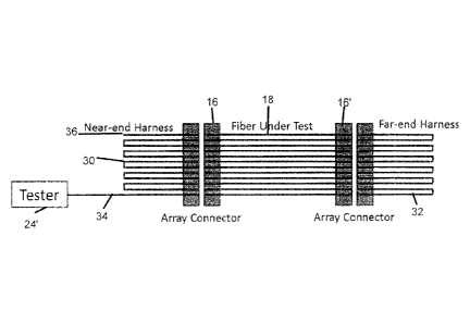
The system comprises two optical harnesses, see
FIG. 3. The first, near-end harness 30, connects to
the array connector on the near-end, the second,
far-end harness 32, connects to the array connector
on the far-end. The near-end harness contains a
lead-in fiber 34 that connects the test instrument
24 (which includes hardware to effect testing,
including ram, rom, one or more cpus, optical signal
generators and receiving devices, user interfaces,
computer/communications interfaces, etc.) to the
first fiber in the array. It also contains loopback
fibers that connect fibers 2 to 3, 4 to 5, 6 to 7,
etc., continuing the pattern to the last fiber.
Assuming an array with an even number of fibers the
last fiber will not have a loop-back but will have a
length of fiber acting as a tail-cord 36. The far-
end harness 32 contains loopback fibers that connect
fibers 1 to 2, 3 to 4, 5 to 6, etc., continuing the
pattern to the last fiber. Each fiber in both
harnesses should be long enough to suppress the
tester's deadzone, allowing each fiber's connector
interface to be measured.
In use, a typical single-ended test instrument
will send an optical pulse out of its test port into
the lead-in fiber. The pulse will travel down fiber
1, loopback into fiber 2, loopback into fiber 3,
continuing on until the end of the tail-cord is
reached. The backscatter and reflections of all
CD. 02815316 2013-05-08
6
events and fiber are propagated into the reverse
direction back into the tester's test port. Thus all
fibers in the array are tested with a single test
instantiation.
In a particular embodiment of this system,
software is included within the tester and/or a
computer software application that analyzes the
measurement data to separate the fibers under test
from the fibers within the test harnesses. Thus,
automated measurement analysis is conducted and
simplistic, illustrative graphics may be utilized to
simplify the visual representation of the fibers
under test.
The loopbacks within both the near-end and far-
end harnesses may be constructed in such a way as to
render each uniquely identifiable. This may assist
in the software analysis in cases where the fiber
under test contains impairments rendering the
analysis difficult or impossible without the
assistance of uniquely identifiable loopbacks. The
method of rendering the loopbacks uniquely
identifiable may take many different forms. One form
may be to make the length of each loopback unique.
Another form may be to add an event, such as non-
reflective loss, at a unique location within the
loopback. Another form may be to add multiple events
and unique locations within the loopback. Multiple
events may be used as a binary code to uniquely
identify each loopback. Or any combination of these
The unique identification allows the virtual
subtraction of the loopback fibers so that the
software or user may measure the fiber
characteristics. It also allows polarity testing.
The harness may be packaged into a robust, easy
to use, mechanical package that protects all the
CA 02815316 2013-05-08
7
loopback fiber and provides a sheathed cable to
protect the fibers interfacing to the connector.
Note that this system and method may also be
useful on single fiber connectors configured as
duplex fiber links, in addition to other multi-fiber
connector systems. Most of today's fiber links are
configured as duplex links with single fiber
connectors. This system and method allows a great
improvement in test time by allowing a bidirectional
test and averaging without the requirement to
physically move the tester to the opposite end of
the fiber. As illustrated in FIG. 4, with the array
connector test harness in accordance with the
disclosure, the method of testing is as follows.
First, the near-end harness 30 is connected at one
end of the fiber network, while the far-end harness
32 is connected at the opposite end, forming a
loopback across the fibers. Next, the test
instrument is connected to lead-in fiber 34, and
testing is performed. For bi-directional testing,
next the test instrument is connected to tail-cord
36 (or if the number of fibers is an odd number,
connection is otherwise made to the last fiber in
the loop) and further testing is performed.
A more extensive explanation of testing is as
follows: First, the near-end launch-cord end harness
and far-end tail-cord end loopback harness 32
together, but without a fiber under test to identify
loopback fiber lengths and any events within the
30 loopbacks, used to uniquely identify each one. This
step can employ a jumper cable to mate the two ends
of the loopback harnesses together, if the MPO
connectors are polarized in such a way that they do
not physically mate. Each of the fibers in this
jumper cable should suitably be chosen to be very
close to the same length to each other (within 0.5
meters). For a duplex fiber embodiment, the near-end
CA 02815316 2013-05-08
8
harness may be implemented as a breakout of the two
fibers into a launch and tail cord.
Next, existing analysis software can be used to
identify the events over the entire length. Each
loopback segment is expected to be at least a
minimum length that is beyond the deadzone of the
tester. The jumper cable may be shorter than this,
which can be preferred to distinguish these segments
from the loopback fibers. Alternatively, the jumper
cable may be longer than the longest loopback
segment. If the length of each loopback segment is
unique and has no internal events, then the median
length of all segments longer than the minimum
length can provide an estimate of the typical
loopback segment length. The number of segments
found should be approximately the total length
(minus any jumper cables and minus the first launch
segment) divided by the median length. Or the number
can be a value that the user provides. If the
longest loopback lengths is built so it is less than
double the shortest loopback length, this can help
identify situations where a connection were missed
thus far in the referencing step.
If each loopback has a non-reflective event,
unique in location and/or loss, and the fiber
segment on either side of the event is longer than
the minimum length needed for the deadzone of the
tester, then twice the median length should indicate
the typical length of a loopback. The loss for each
loopback segment can even be made adjustable by
mechanically bending the fiber. Combined with a
real-time trace, adjusting the loss would visibly
show where the loopback fiber was located within the
total fiber span to help with correcting cross-
connect issues. However, this could impact launch
conditions for multimode fibers.
If the binary encoding form is used, where
CA 02815316 2013-05-08
9
spaced events are provided to generate a binary
identifying code of events, then each loopback
segment could be identified by a series of
relatively closely spaced events surrounded by
segments at least as long as the minimum length.
Other non-binary encoding can be used.
Further alternatively, the user could also
enter the lengths of each loopback manually.
Another approach is to calibrate the loopback
harnesses during manufacturing and provide the
length and identifying event information with the
harnesses that could be entered into the instrument,
either manually or by encoding information provided
by the harness to the instrument on connection or
setup inquiry from the instrument.
Still further, all loopback harnesses can be
manufactured so that the tolerance of the lengths of
each loopback fiber is less than the difference
between the lengths of each loopback, and this
information recorded in the tester, so the lengths
of each loopback must match a narrow range to help
identify each unique loopback segment. For each
event, an algorithm can check that the following
event/s match the expected pattern within tolerance.
Both forward and reverse direction of the pattern
can be checked, since either end of the near-end
harness could be connected.
The testing operation continues as follows:
The fiber under test for MPO and duplex ribbon
cable should measure nearly the same length on each
segment. This information can help identify the
segments, though is not an absolutely necessary
condition.
Existing analysis software can be used to
identify the events over the entire length.
The total length minus the launch, tail and
loopback can be divided by the number of MPO fibers
CA 02815316 2013-05-08
expected to give the typical length of the fiber
under test.
After locating the event at the launch, then
adding the typical fiber under test length, then the
5 events within the measurement tolerance at this
position along the measured signal can be compared
to each of the expected loopbacks (since it is
possible for some of the fibers to be cross-
connected). This matching can be repeated for each
10 length.
In a particular use configuration, for example,
employing different lengths to assist in
distinguishing fibers, lead in fiber 34' may include
a 90 meter launch fiber, while tail cord 36' may
include a 110 meter launch fiber. Far end harness
32' may include 90 meter fiber 38 and 110 meter
fiber 40.
In accordance with the disclosure herein, an
improved method, apparatus and system is provided
for providing an array connector harness for optical
network testing. The system, method and apparatus
provide easier, quicker testing of multi-fiber
network connections. Additionally, it allows
polarity testing and identification.
While a preferred embodiment of the present
invention has been shown and described, it will be
apparent to those skilled in the art that many
changes and modifications may be made without
departing from the invention in its broader aspects.
The appended claims are therefore intended to cover
all such changes and modifications as fall within
the true spirit and scope of the invention.