Note: Descriptions are shown in the official language in which they were submitted.
CA 0 2 815513 2014-12-16
WO 2012/067787 PCT/US2011/058238
DEVICES FOR DELIVERING A MEDICAMENT AND METHODS FOR
AMELIORATING PAIN
[0001] (Blank)
TECHNICAL FIELD
[0002] The embodiments described herein relate generally to devices
and methods for pain management¨particularly, though not exclusively, to
the management of pain associated with headaches, facial aches, and the
like.
INTRODUCTION
[0003] Conventional methods for treating pain associated with
headaches and facial aches are not as safe or effective as desired. By way of
example, non-steroldal anti-inflammatory drugs (NSAIDs), such as the COX-2
brand of medications, must be used sparingly and only for short durations in
view of their potential for causing ulcers and heart attacks¨a drawback that
is
further compounded by the inefficacy of these medications in a large number
of patients. The use of narcotics is likewise undesirable in view of their
potentially addictive properties. In addition, the use of tryptamine-based
drugs¨which include but are not limited to sumatriptan (sold under the
tradename IMITREX by GlaxoSmithKline) and zolmitriptan (sold under the
tradename ZOMIG by AstroZeneca)¨is undesirable in view of the costliness
and potentially high toxicity of these drugs.
[0004] One method that has been employed for controlling the pain
associated with headaches and facial aches is known as an SPG block. In
CA 02815513 2015-03-30
-2-
this approach, anesthetic is applied to a sphenopalatine ganglion (SPG) of
a patient by a trained medical professional, who typically inserts a cotton-
tipped applicator soaked in the anesthetic into the nostril of a patient in
order to apply the anesthetic to the SPG. Using the middle turbinate as an
anatomical landmark, the soaked cotton-tipped applicators are pushed
upwards in what is essentially a blind advance (the success of which
depends very heavily on the skill and experience of the physician). Clearly,
the efficacy and safety of this procedure leave much to be desired.
Moreover, the efficacy and safety of conventional SPG blocks have been
significantly compromised by a long-held but mistaken belief amongst
clinicians that the SPG is located posterior to the superior turbinate¨which
it is not.
[0005] In short, there is a pressing need amongst patients and
clinicians for safer and more effective methods and devices for achieving
an SPG block¨particularly ones that can be employed directly by a patient
without the assistance or supervision of a trained medical professional.
SUMMARY
[0006] The scope of the present invention is defined solely by the
appended claims, and is not affected to any degree by the statements
within this summary.
[0007] A device for delivering a medicament to a patient in need
thereof includes: (a) an injector including a first end configured to remain
outside a nasal passage of the patient and a second end configured for
entry into the nasal passage of the patient, wherein the injector is
moveable between a storage position and an engaging position; and (b) an
introducer configured for engagement with a nostril of the patient, wherein
the introducer includes a passageway configured for slidably receiving the
injector, and wherein the introducer includes a curvature along a portion
thereof adjacent to the passageway.
[0007a] A further device for delivering a medicament to a patient in
need thereof includes: (a) an injector including a first end configured to
CA 02815513 2015-03-30
-2a-
remain outside a nasal passage of the patient and a second end configured
for entry into the nasal passage of the patient; (b) an introducer configured
for engagement with a nostril of the patient, wherein the introducer
comprises a passageway configured for slidably receiving the injector, and
the passageway slidably receiving a syringe within the introducer, wherein
the introducer comprises a curvature along a portion thereof adjacent to
and surrounding a distal length of the passageway, wherein the injector is
moveable, relative to the introducer, between a storage position and an
engaging position; and (c) a housing of the introducer, wherein a first end
of the housing is configured to remain outside a nasal passage of the
patient and wherein a second end of the housing comprises the curvature
portion of the introducer.
[0007b] A still further
device for delivering a medicament to a patient in
need thereof includes: (a) an injector comprising: a first, proximal, end
including a hub with a syringe-attachment Luer structure, said first end
configured to remain outside a nasal passage of the patient; a second,
distal, end configured for entry into the nasal passage of the patient; and a
tubular injector body between the first end and second end; and (b) an
introducer configured for engagement with a nostril of the patient, wherein
the introducer comprises an introducer passageway configured for slidably
receiving the injector, where the introducer passageway slidably receives a
syringe barrel when a hub-attached syringe is advanced distally within the
introducer. The introducer comprises a curvature along a distal portion
thereof that surrounds and defines a distal longitudinal curvature of the
passageway. The injector is moveable, relative to the introducer, between
a storage position and an engaging position. The hub comprises a radially-
extending stop bar and wherein an inward-facing surface of the introducer
passageway comprises a pair of substantially parallel longitudinal ledges
configured to abut against and be tracked along by the stop bar on first and
second opposing sides of the stop bar, where said ledges provide for a first
longitudinal linear path and a second longitudinal linear path, each parallel
to the other and to a central
CA 02815513 2015-03-30
-2b-
longitudinal axis, separated radially from each other by a predetermined
number
of degrees of rotation corresponding to a desired medicament delivery angle.
The length of the ledges corresponds to at least a portion of longitudinal
distance
between the storage position and the engaging position of the injector
relative to
the introducer. The tubular injector body comprises one or a plurality of
apertures along a side of the flexible tube adjacent to the second end.
[0008] A method for
ameliorating pain in a patient includes (a) introducing
the injector of a device of a type described above through the nasal passage
of
the patient into a region substantially medial and/or posterior
CA 02815513 2013-04-22
WO 2012/067787
PCT/US2011/058238
-3-
and/or inferior to a sphenopalatine ganglion of the patient; and (b)
delivering a
medicament from the injector superiorly and/or laterally and/or anteriorly
towards the sphenopalatine ganglion.
BRIEF DESCRIPTION OF THE DRAWINGS
[0009] FIG. 1 shows a cross-sectional side view of a first device
for
delivering a medicament to a patient in need thereof prior to insertion of the
device into a patient's nostril in accordance with principles described
herein.
[0010] FIG. 2 shows a cross-sectional top plan view of the device
of FIG.
1 taken along the line 2-2.
[0011] FIG. 3 shows a cross-sectional side view of the device of
FIG. 1
after the introducer has been engaged with a patient's nostril in accordance
with principles described herein.
[0012] FIG. 4 shows a cross-sectional side view of the device of
FIG. 1
after the introducer has been engaged with a patient's nostril and after the
injector has been moved from its storage position to an engaging position that
positions the second end of the injector medial, posterior, and inferior to
the
sphenopalatine ganglion.
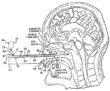
[0013] FIG. 5 shows a median cross-sectional view of a human head
with
the SPG 2 shown in its correct anatomical position posterior to the middle
turbinate 4.
[0014] FIG. 6 shows a side elevation of a second device for
delivering a
medicament to a patient in need thereof prior to insertion of the hub into the
housing and with the injector in its storage position.
[0015] FIG. 7 shows a partial cross-sectional side view of the
device of
FIG. 6 with the injector in its storage position.
[0016] FIG. 8 shows a partial cross-sectional side view of the
device of
FIG. 6 with the injector in an engaging position.
[0017] FIG. 9 shows an exploded perspective view of the device of
FIG.
6.
CA 02815513 2013-04-22
WO 2012/067787
PCT/US2011/058238
-4-
DETAILED DESCRIPTION
[0018] Heretofore unknown and highly effective methods for
ameliorating
pain in a patient¨particularly though not exclusively the pain associated with
headaches, facial aches, and the like¨and user-friendly devices enabling
facile self-administration of medicaments in accordance with these methods,
have been discovered and are described herein. As further explained below,
the methods and devices described herein enable delivery of a medicament
superiorly and/or laterally and/or anteriorly towards the sphenopalatine
ganglion from a region substantially medial and/or posterior and/or inferior
to
the sphenopalatine ganglion.
[0019] As used herein, the phrase "towards the sphenopalatine
ganglion"
and similar such phrases used in reference to the delivery of a medicament
are intended to include the SPG itself as well as the pterygopalatine fossa
which houses the SPG and the sphenopalatine foramen.
[0020] By way of introduction, FIG. 5 shows a median cross-
sectional
view of a human head that correctly identifies the location of the SPG 2 as
being posterior to the middle turbinate 4¨not posterior to the superior
turbinate 6 or at the apex 8 of the nasal cavity in proximity to cribriform
plate 9
as various clinicians have erroneously thought. In addition, the correct
location of the SPG 2 is actually offset laterally from the plane of the
drawing¨in other words, the SPG does not lie in'a two-dimensional plane
with respect to the depicted cross-section, as has also been erroneously held
by various clinicians.
[0021] In United States Patent No. 4,886,493, Jordan Yee describes
a
process for performing an SPG block in which a tube is inserted through the
nostril of a patient in an attempt to deliver medication to the
pterygopalatine
fossa, which houses the SPG. Unfortunately, as shown in FIG. 3 of U.S.
Patent No. 4,886,493, the location of the pterygopalatine fossa (18) has been
misidentified as lying posterior to the superior turbinate and in an x-y plane
accessible by a straight line from the nostril via a tube (11). As a result of
this
misunderstanding¨in addition to the expected lack of efficacy one would
expect from delivering medication to the wrong location¨the terminal end
CA 02815513 2013-04-22
WO 2012/067787
PCT/US2011/058238
-5-
(13) of the Yee device comes perilously close to contacting the delicate
cribriform plate. Since the cribriform plate is sievelike and in communication
with the frontal lobe of the brain, it is extremely dangerous to introduce
anesthetics in close proximity to this plate since they can easily penetrate
through to the frontal lobe.
[0022] United States Patent No. 6,491,940 B1 to Bruce H. Levin
describes an alternative procedure for performing an SPG block. In contrast
to the Yee patent described above, U.S. Patent No. 6,491,940 B1 appears to
recognize the lateral offset of the SPG since it describes a curved rather
than
straight body (100) for introducing anesthetic. Unfortunately, similarly to
the
Yee patent, the Levin patent also fails to recognize that the correct location
of
the SPG is posterior to the middle turbinate¨not at the apex of the nasal
cavity as shown in FIG. 4A of Levin and as described therein (e.g., col. 72,
lines 20-22). Thus, as in the case of the Yee patent, the process described in
the Levin patent once again introduces an anesthetic delivering device in
dangerously close proximity to the cribriform plate with all of the attendant
risks and diminished efficacies associated therewith.
[0023] United States Patent No. 6,322,542 BI, assigned to
AstraZeneca,
describes a device for delivering medicaments into the nasal cavity of a
patient. Although the stated objective of this device is to effectively
deliver
medicament to the posterior region of the nasal cavity (col. 1, lines 29-32),
its
configuration (e.g., the linearity of tubular member 35) is ill-adapted to
delivering medicament to or in proximity to the SPG. Rather, medicament will
be delivered largely to the region 7 shown in FIG. 5 of the present
application.
The delivery of anesthetics in proximity to the region 7 is highly undesirable
inasmuch as the anesthetics can readily suppress the gag reflex, thereby
creating a risk of aspiration pneumonia.
[0024] While neither desiring to be bound by any particular theory,
nor
intending to affect in any measure the scope of the appended claims or their
equivalents, the following background information is provided regarding
present-day understanding of the anatomy of the SPG in order to further
elucidate the description of the devices and methods provided hereinbelow.
CA 02815513 2013-04-22
WO 2012/067787
PCT/US2011/058238
-6-
[0025] The SPG (also known as the pteFygopalatine ganglion) is the
largest group of neurons outside the cranial cavity and lies in the
pterygopalatine fossa, which is approximately 1-cm wide and approximately 2-
cm high. The pterygopalatine fossa is bordered anteriorly by the posterior
wall of the maxillary sinus, posteriorly by the medial plate of the pterygoid
process, medially by the perpendicular plate of the palatine bone, and
superiorly by the sphenoid sinus. Laterally, the pterygopalatine fossa
communicates with the infratemporal fosse.
[0026] The SPG within the fossa is located posterior to the middle
turbinate of the nose and lies a few millimeters (1 mm to 5 mm) deep to the
lateral nasal mucosa. The SPG has a complex neural center and multiple
connections. The SPG is suspended from the maxillary branch of trigeminal
nerve at the pterygopalatine fossa via the pterygopalatine nerves, and lies
medial to the maxillary branch when viewed in the saggital plane. Posteriorly,
the SPG is connected to the vidian nerve. The SPG itself has efferent
branches and forms the superior posterior lateral nasal and pharyngeal
nerves. Caudally, the ganglion (SPG) is in direct connection with the greater
and lesser palatine nerves.
[0027] The SPG has sensory, motor and autonomic components. The
sensory fibers arise from the maxillary nerve, pass through the SPG, and are
distributed to the nasal membranes, the soft palate and some parts of the
pharynx. A few motor nerves are also believed to be carried with the sensory
trunks.
[0028] The autonomic innervations of the SPG are more complex. The
sympathetic component begins with preganglionic sympathetic fibers
originating in the upper thoracic spinal cord, forming the white ramie
communicantes, coursing through the sympathetic ganglion, where the
preganglionic fibers synapse with the postganglionic ones. The
postganglionic fibers then join the carotid nerves before branching off and
traveling through the deep petrosal and vidian nerves. The postganglionic
sympathetic nerves continue their path through the SPG on their way to the
lacrimal gland and nasal and palatine mucosa.
CA 02815513 2013-04-22
WO 2012/067787
PCT/US2011/058238
-7-
[0029] The SPG is usually considered parasympathetic in function.
The
parasympathetic component of SPG has its preganglionic origin in the
superior salivatory nucleus then travels through a portion of the facial nerve
(VII) before forming the greater petrosal nerve to form the vidian nerve,
which
ends in the SPG. Within the ganglion, the preganglionic fibers synapse with
their postganglionic cells and continue on to the nasal mucosa, and one
branch travels with the maxillary nerve to the lacrimal gland. n
[0030] Notwithstanding the description above, and regardless of the
currently-held theories respecting the anatomy of the SPG, a safe and
effective amelioration of pain can be achieved as a result of using the
devices
and methods described below. Although representative devices 10 and 54
will be described in reference to FIGS. 1-4 and FIGS. 6-9, respectively, it is
to
be understood that these representative devices are merely illustrative and
that alternative structures can likewise be utilized for delivering a
medicament
in accordance with principles described herein. It is to be understood that
elements and features of the various representative devices described below
may be combined in different ways to produce new embodiments that likewise
fall within the scope of the present teachings. The drawings and the
description below have been provided solely by way of illustration, and are
not
intended to limit the scope of the appended claims or their equivalents.
[0031] FIGS. 1-4 show a representative device 10 for delivering a
medicament to a patient in need thereof. The device 10 includes an injector
12 comprising a first end 29 configured to remain outside a nasal passage of
the patient and a second end 30 configured for entry into the nasal passage of
the patient. Device 10 further includes an introducer 18 configured for
engagement with a nostril of the patient and comprising a passageway 48
configured for slidably receving the injector 12. The injector 12 is moveable
between a storage position (best shown by FIG. 1) preceding engagement of
introducer 18 with a patient's nostril, and an engaging position (best shown
by
FIG. 4) pursuant to engagement of introducer 18 with the patient's nostril.
However, upon the initial engagement of introducer 18 with a patient's
nostril,
the injector 12 is desirably maintained¨at least for a time¨in a storage
CA 02815513 2013-04-22
WO 2012/067787
PCT/US2011/058238
-8-
position (best shown by FIG. 3) until it is deliberately moved to an engaging
position (best shown by FIG. 4) under the direction of a user. In some
embodiments, the engaging position of injector 12 is situated medial and/or
inferior to the SPG. In other embodiments, the engaging position of injector
12 is situated medial, inferior, and posterior to the SPG, as best shown by
FIG. 4.
[0032] As used herein, the phrases "storage position" and "engaging
position" are each intended to encompass multiple positions within a selected
range. For example, in some embodiments, the degree to which injector 12 is
extended into the nostril of a first patient (e.g., a child) will vary from
the
degree to which injector 12 is extended into the nostril of a second patient
(e.g., an adult male). Notwithstanding, the phrase "engaging position" is
intended to encompass many variations in the precise position of injector 12
within the nostril, any of which are properly regarded as being medial and/or
posterior and/or inferior to the SPG. In some embodiments, injector 12 is not
slidable within introducer 18 but rather is fixed in a predetermined position
so
as to be medial and/or inferior to the SPG upon engagement of introducer 18
with a patient's nostril. In other embodiments, injector 12 is not slidable
within
introducer 18 but rather is fixed in a predetermined position so as to be
medial, posterior, and inferior to the SPG upon engagement of introducer 18
with a patient's nostril.
[0033] The injector 12 comprises a tubular section 24 (a so-called
cobra
tube in recognition of the tube's extensibility) that includes a channel 22
extending from first end 29 to second end 30 and configured for receiving a
medicament. In some embodiments, tubular section 24 has an outer diameter
of about 5 mm and channel 22 has an inner diameter of about 2 mm.
Throughout this description, measurements and distances such as the
diameters just given are to be strictly regarded as being merely
representative
and in no way limiting and/or fixed. Considerable variation in all
measurements and distances provided in this description is possible, as will
be readily appreciated by one of ordinary skill in the art.
CA 02815513 2013-04-22
WO 2012/067787
PCT/US2011/058238
-9-
[0034] In some embodiments, the second end 30 of injector 12
contains
a nozzle 28 having a tip 34 that contains one or a plurality of apertures 36
configured for spraying a medicament superiorly and/or laterally and/or
anteriorly towards the SPG. In some embodiments, nozzle 28 is configured
for spraying a medicament laterally and/or superiorly towards the SPG, and in
other embodiments, nozzle 28 is configured for spraying a medicament
laterally, superiorly, and anteriorly towards the SPG.
[0035] In some embodiments, nozzle 28 extends at an upward angle of
inclination from second end 30 of injector 12. In some embodiments, nozzle
28 extends in a lateral, anterior, and superior direction at an angle of
inclination ranging from about 45 degrees to about 60 degrees to
accommodate varying patient anatomies in which the SPG resides in a lateral
cave posterior to the middle turbinate. In some embodiments, nozzle 28 has
a length ranging from about 2 mm to about 5 mm. In some embodiments,
injector 12 is designed to exhibit handedness, such that in some
embodiments, injector 12 is configured for engagement with a left-side nostril
of a patient, whereas in other embodiments, injector 12 is configured for
engagement with a right-side nostril of the patient (with the contour of a
left-
handed injector being generally complementary to the contour of a right-
handed injector).
[0036] The introducer 18 can be aimed into a nostril to provide a
horizontal pathway substantially parallel to the bottom of the nasal cavity or
floor of the nose¨such that introducer 18 is supported on the bottom of the
nasal cavity¨to a position medial to the inferior turbinate. This self-seating
feature of introducer 18 facilitates quick and accurate usage by a patient
without necessitating supervision from a medical professional. In some
embodiments, introducer 18 provides an extended pathway of between about
1.5 cm and about 2 cm into the nostril. Once introducer 18 is placed firmly
against the nose, the tip of the nose will tend to point superiorly. The
tubular
section 24 of injector 12 can then be pushed partially or completely into the
back of the nostril. In order to accommodate the slightly curved nature of the
interior anatomy of the nose, the passageway 48 in which tubular section 24
CA 02815513 2013-04-22
WO 2012/067787
PCT/US2011/058238
-10-
lies can be curved slightly to the ipsilateral nostril by about 5 to about 20
degrees. Once tubular section 24 is in position, a medicament can then be
delivered to the SPG from nozzle 28 to exert the desired SPG blocking effect.
In some embodiments, device 10 is provided with an optional safety abutment
stop to limit the extent of travel into the nostril available to injector 12.
[0037] As best shown by FIGS. 1, 3, and 4, introducer 18 contains a
first
portion 44 and a second portion 38. In some embodiments, a cross-sectional
area of first portion 44 is larger than a cross-sectional area of second
portion
38. In some embodiments, first portion 44 is generally concave and has a
contour 46 configured to be complementary in shape to an interior of the
nostril so as to substantially conform therewith. In some embodiments,
narrow second portion 38 has a rounded convex portion 39 and an underside
40 having a generally flat surface 42. The passageway 48 of introducer 18
slidably receives tubular section 24 of injector 12 and, in some embodiments,
has a diameter of between about 6 mm and about 7 mm. In some
embodiments, second portion 38 of introducer 18 contains a nostril-engaging
tip that extends from about 1 cm to about 3 cm. In some embodiments, first
portion 44 of introducer 18 extends from about 2 cm to about 3 cm. In some
embodiments, introducer 18 is designed to exhibit handedness, such that in
some embodiments, introducer 18 is configured for engagement with a left-
side nostril of a patient, whereas in other embodiments, introducer 18 is
configured for engagement with a right-side nostril of the patient (with the
contour of a left-handed introducer being generally complementary to the
contour of a right-handed introducer).
[0038] In some embodiments, device 10 further includes a container
14
in communication with first end 29 and channel 22 of injector 12, which is
configured for holding a medicament 16 (e.g., anesthetic). In some
embodiments, as shown in FIGS. 1, 3, and 4, container 14 is supported on a
stem 26 having a lower section 31 which, in some embodiments, has an outer
diameter substantially the same as that of tubular section 24. Lower section
31 can extend outwardly and/or upwardly and/or at an angle of inclination
from first end 29 of injector 12 and, in some embodiments, connects with an
CA 02815513 2013-04-22
WO 2012/067787
PCT/US2011/058238
-11-
upper section 32 having an enlarged diameter configured to receive an outlet
33 of container 14. Analogous to lower section 31, upper section 32 can
extend outwardly and/or upwardly and/or at an angle of inclination.
[0039] In some embodiments, container 14 is operatively connected,
mounted or otherwise secured to upper stem section 32 and is fully or
partially
filled with a medicament 16. Since container 14 is in communication with
channel 22 of injector 12, medicament 16 can be delivered along tubular
section 24 and released through one or more apertures 36 of nozzle 28.
Container 14 can be formed of plastic, metal or the like, and can be
squeezable and/or pressurized to facilitate medicament delivery into channel
22. In some embodiments, container .14 is replaced by a port (not shown),
such that a medicament can be introduced through the port into upper section
32 by a delivery device such as a syringe.
[0040] In some embodiments, device 10 further includes an optional
handle 20 connected to a rear portion of introducer 18 adjacent first portion
44. The handle 20 includes an upwardly facing groove 50 that provides a
track 52 configured to receive and in communication with passageway 48 of
introducer 18 to slidably receive tubular section 24 of injector 12. In some
embodiments, track 52 has a depth or width of between about 6 mm and
about 7 mm. Handle 20 is configured for movement towards a patient's face,
such that posterior movement of handle 20 moves introducer 18 into
engagement with the nostril of the patient.
[0041] Injector 12, introducer 18, and handle 20 can be formed from
all
manner of materials including but not limited to flexible, rigid or semi-rigid
polymeric materials (e.g., plastics, rubbers, etc.), metals and alloys
thereof,
and the like, and combinations thereof. In some embodiments, injector 12 is
formed of a flexible plastic, introducer 18 is formed of an elastomeric and/or
resilient plastic or rubber, and handle 20 is formed of plastic. In some
embodiments, one or more of injector 12, introducer 18, and handle 20 is
designed from a material so as to be disposable and/or biodegradable.
[0042] While the representative device 10 described above can be
used
to deliver a medicament superiorly and/or laterally and/or anteriorly towards
a
CA 02815513 2013-04-22
WO 2012/067787
PCT/US2011/058238
-12-
sphenopalatine ganglion of a patient in accordance with the principles set
forth herein, alternative structures can likewise be employed to similarly
accomplish such a delivery.
[0043] Solely by way of example, a delivery tube having a curved
portion
at one of its ends configured for insertion into a patient's nostril¨analogous
to
the angled nozzle 28 provided on the second end 30 of injector 12¨can be
housed within a substantially cylindrical (e.g., pen- or cigar-shaped)
housing.
The delivery tube can be formed of a flexible or semi-rigid material (such as
a
plastic) such that it can be maintained in a substantially linear or non-
curved
arrangement while in its storage position within the housing but readily
restored to its curved configuration when extended from the housing into an
engaging position. In such a device, one or more internal surfaces of the
external housing acts to straighten or restrain¨completely or at least
partially¨the inherent curvature of the delivery tube until such time as the
delivery tube is moved to an engaging position, whereupon the curvature of
the tube is restored. In some embodiments, at least a portion of the delivery
tube (e.g., the end designed to emit medicament) can be expandable if
desired (e.g., when air, oxygen and/or other gases, and/or medicaments are
forced through the tube under pressure).
[0044] By providing one or more optional indicial markings on the
cylindrical housing described above, a user can readily identify the direction
of
curvature of the delivery tube stored inside, such that by turning the housing
around and arc of 360 degrees, the user can select any desired direction of
spray for delivering a medicament through the delivery tube. Simply by
rotating the housing, the direction of spray can be incrementally changed
through a continuous arc between 0 degrees and 360 degrees inclusive. In
design, one end of the housing can be fitted with a luer lock configured to
engage with a syringe containing the medicament. Alternatively, the end of
the housing configured to remain outside the nostril can be fitted with a
septum or similar such membrane through which a medicament can be
introduced into the delivery tube housed therein.
CA 02815513 2013-04-22
WO 2012/067787
PCT/US2011/058238
-13-
[0045] Numerous other modifications to the delivery devices
described
herein, as well as alternative structures, are likewise contemplated for use
to
the extent they similarly allow for the delivery of a medicament superiorly
and/or laterally and/or anteriorly towards a sphenopalatine ganglion of a
patient in accordance with the present teachings. By way of example, the
portion of the device configured for insertion into a patient's nostril (e.g.,
a
portion of the injector 12 described above) can be formed from any
therapeutically acceptable malleable material (e.g., plastics, metals, metal
alloys, and the like) capable of receiving and retaining a desired shape when
manipulated by a user. (e.g., increased or decreased curvature of the angled
nozzle 28 provided on the second end 30 of injector 12). Such a feature may
be desirable, for example, when a clinician wishes to customize the exact
geometry of a device before using it on a patient in a clinical setting.
[0046] FIGS. 6-9 show a representative device 54 for delivering a
medicament to a patient in need thereof. The device 54 includes an injector
56 comprising a first end 58 configured to remain outside a nasal passage of
the patient and a second end 60 configured for entry into the nasal passage of
the patient. Device 54 further includes an introducer 62 configured for
engagement with a nostril of the patient and comprising a passageway 64
configured for slidably receving the injector 56. The injector 56 is moveable
between a storage position (best shown by FIGS. 6 and 7) preceding
engagement of introducer 62 with a patient's nostril, and an engaging position
(best shown by FIG. 8) pursuant to engagement of introducer 62 with the
patient's nostril.
[0047] As best shown by FIGS. 6 and 7, the injector 56 is coupled
to a
hub 66 fitted with a luer lock mechanism configured to engage with the
threads of a syringe (not shown) containing a medicament to be delivered to a
patient. As best shown by FIGS. 7-9, the hub 66 is coupled to a stop bar 68
that is compressible. Prior to engagement with a syringe, hub 66 is
configured to remain outside of housing 70 and to resist rotation therein
since
stop bar 68 is positioned within a keyed slot 72 formed by the two halves of
housing 70. As hub 66 is pressed axially into housing 70 (e.g., by a syringe
CA 02815513 2013-04-22
WO 2012/067787
PCT/US2011/058238
-14-
coupled to the luer lock mechanism on hub 66), stop bar 68 travels along
keyed slot 72 until it reaches lip 74 at which point stop bar 68 engages lip
74,
thereby preventing retraction of hub 66 from the interior of housing 70, and
at
which point hub 66 (and the syringe coupled thereto) become rotatable over a
fixed range. The irreversibility of the axial travel of hub 66 within housing
70
provides a useful way for a practitioner to readily distinguish a used device
from an unused one¨namely, if hub 66 does not protrude from housing 70,
the device has previously been used.
[0048] As may best be understood from a consideration of FIGS. 8
and
9, stop bar 68 is further configured to act in conjunction with a ledge 78
inside
of housing 70 such that the range of rotation of hub 66 (and the syringe
coupled thereto) is limited to predetermined angles (e.g., about 45 clockwise
or 45' counterclockwise). Rotation beyond the predetermined angles (which
are determined based on positioning of ledge 78) is prevented when stop bar
68 butts up against ledge 78. This feature facilitates accuracy of use by a
user by limiting the positions from which medicament can be introduced from
injector 56 to those having the desired trajectory towards a target site.
[0049] As best shown by FIG. 8, injector 56¨which in some
embodiments comprises a flexible plastic tube having shape memory¨retains
a slight curvature that is conferred upon it by the curved introducer 62
during
storage. By virtue of this curvature, and by providing one or a plurality of
apertures along the side of second end 60, the injector 56 is designed to be
used in both the left-side and right-side nostrils of a patient without regard
to
handedness.
[0050] In some embodiments, the diameter of the one or plurality of
apertures along the side of second end 60 of injector 56 is smaller than an
outer diameter of the flexible plastic tube, such that the liquid expelled
through
the aperture upon pressing the plunger of the syringe exits forcefully. In
some
embodiments, depending on the flexibility of the plastic tube, injector 56
undergoes further curvature under the pressure exerted by depression of the
syringe plunger (e.g., in a direction away from that of the liquid exiting the
aperture). In some embodiments, the diameter of the one or plurality of
CA 02815513 2013-04-22
WO 2012/067787
PCT/US2011/058238
-15-
apertures is smaller than an inner diameter of the flexible plastic tube. In
some embodiments, the flexible plastic tube comprises a nylon resin (e.g.,
such as that sold under the tradename PEBAX 72D). In some embodiments,
the flexible plastic tube comprises PEBAX 72D, has an outer diameter 4) of
0.039 0.001, has a wall thickness of 0.005 0.001 (i.e., five thousandths
of
an inch), and has an aperture with a diameter of 0.005 0,001. In some
embodiments, the aperture is oriented at a 50 angle in a direction oriented
towards the hub. In some embodiments, introducer 62, housing 70, keyed
slot 72, lip 74, and ledge 78 are integrally formed (in some embodiments, as
two complementary molded halves press fit and/or bonded together, such as
with adhesives, sonic welding or the like) and, in some embodiments, these
portions comprise polycarbonate. In some embodiments, hub 66 and stop bar
68 likewise comprise polycarbonate.
0051] A method for ameliorating pain in a patient in accordance
with the
present teachings includes delivering a medicament superiorly and/or laterally
and/or anteriorly towards a sphenopalatine ganglion of a patient using a
device as described herein. In some embodiments, the medicament is
delivered laterally and/or superiorly towards the SPG. In other embodiments,
the medicament is delivered laterally, superiorly, and anteriorly towards the
SPG.
[00521 In some embodiments, a method for ameliorating pain in a
patient
includes (a) introducing an injector 12 through a nasal passage of the patient
into a region substantially medial and/or posterior and/or inferior to an SPG
of
the patient; and (b) delivering a medicament from injector 12 superiorly
and/or
laterally and/or anteriorly towards the SPG. In some embodiments, injector
12 is introduced through a nasal passage of the patient into a region
substantially medial and/or inferior to the SPG, whereas in other embodiments
the injector 12 is introduced into a region substantially medial, inferior,
and
posterior to the SPG. In some embodiments, the medicament is delivered
laterally and/or superiorly towards the SPG, whereas in other embodiments,
the medicament is delivered laterally, superiorly, and anteriorly towards the
SPG. In some embodiments, injector 12 has a second end 30 containing one
CA 02815513 2013-04-22
WO 2012/067787
PCT/US2011/058238
-16-
or a plurality of apertures 36 through which a medicament is sprayed towards
the SPG.
[0053] In some embodiments, injector 12 is slidably received in an
introducer 18, as described above, and the method further includes (c)
engaging introducer 18 with a nostril of the patient, such that a portion of
the
patient's nose is lifted upon engagement with introducer 18; and (d) sliding
injector 12 from a storage position to an engaging position after introducer
18
is engaged with the nostril. As described above, the engaging position of
injector 12 is situated medial and/or posterior and/or inferior to the SPG¨
medial and/or inferior in some embodiments, and medial, inferior, and
posterior in other embodiments. In some embodiments, the medicament is
provided in a container 14 connected to and in communication with injector
12, as described above, and the method further includes (e) squeezing
container 14 containing the medicament in order to spray the medicament
towards the SPG.
[0054] In some embodiments, the method includes pushing introducer
18
snugly and comfortably within a nostril to lift the tip of the patient's nose
before positioning the nozzle 28 of injector 12 in proximity to the SPG,
sliding
tubular section 24 of injector 12 through passageway 48 in introducer 18,
and/or sliding tubular section 24 of injector 12 on a track 52 of handle 20.
[0055] All manner of medicaments suitable for introduction at or in
the
vicinity of the SPG are contemplated for use in accordance with the present
teachings. The physical state of the medicament includes but is not limited to
liquids, solids, semi-solids, suspensions, powders, pastes, gels, and the
like,
and combinations thereof. In some embodiments, the medicament is
provided in an at least partially liquid form. In some embodiments, the
medicament contains an anesthetic.
[0056] Anesthetics that may be used in accordance with embodiments
described herein include but are not limited to ambucaine, amolanone,
amylocaine, benoxinate, betoxycaine, biphenamine, bupivacaine, butacaine,
butamben, butanilicicaine, butethamine, butoxycaine, carticaine,
cocaethylene, cocaine, cyclomethycaine, dibucaine, dimethisoquin,
CA 02815513 2013-04-22
WO 2012/067787
PCT/US2011/058238
-17-
dimethocaine, diperodon, dyclonine, ecgonidine, ecgonine, ethyl
aminobenzoate, ethyl chloride, etidocaine, (1-eucaine, euprocin, fenalcomine,
fomocaine, hexylcaine, hydroxyprocaine, hydroxytetracaine, isobutyl p-
aminobenzoate, leucinocaine mesylate, levoxadrol, lidocaine, meperidine,
mepivacaine, meprylcaine, metabutoxycaine, methyl chloride, myrtecaine,
naepaine, octacaine, orthocaine, oxethazaine, parethoxycaine, phenacaine,
phenol, a pipecoloxylidide, piperocaine, piridocaine, polidocanol, pramoxine,
sameridine, prilocaine, propanocaine, proparacaine, propipocaine,
propoxycaine, pseudococaine, pyrrocaine, quinine urea, risocaine,
ropivacaine, salicyl alcohol, tetracaine, tolycaine, trimecaine, veratridine,
zolamine, and the like, and combinations thereof, as well as all optical
and/or
stereoisomers thereof, and all pharmaceutically acceptable salts thereof.
[0057] In some embodiments, the medicament comprises an anesthetic
selected from the group consisting of benzocaine, tetracaine, ropivacaine,
lidocaine, water, saline, and combinations thereof. In some embodiments, the
medicament comprises water and/or saline having a temperature of less than
about 10 C and in other embodiments of less than about 5 C. In some
embodiments, the medicament comprises water and/or saline having a
temperature of about 4 C. In some embodiments, the medicament
comprises a combination of benzocaine, tetracaine, and ropivacaine. In some
embodiments, the medicament comprises an anesthetic comprising about
14% benzocaine, about 2% tetracaine, and about 1% ropivacaine by weight
based on total weight of the anesthetic.
[0058] In some embodiments, a mixture of benzocaine, tetracaine,
and
ropivacaine is used to achieve a fast onset of SPG block as well as to prolong
the effects of pain relief, thereby reducing the need for repeated
applications
and minimizing any potential dose-related complications and/or side effects.
Benzocaine¨which is quite effective in topical use and has a toxic dose in
excess of about 200 mg¨has an onset time of about 30 seconds and lasts for
between about 0.5 and about 1 hour. Benzocaine provides an almost
immediate onset of pain relief and may increase the absorption of other local
anesthetics when mixed therewith. Ropivacaine¨which has a toxic dose of
CA 02815513 2013-04-22
WO 2012/067787 PCT/US2011/058238
-18-
about 175 mg¨typically has a slow onset but lasts for between about 2 and
about 6 hours. Ropivacaine provides an extended nerve block and lasting
pain relief. Tetracaine is a very intense local anesthetic having a fast onset
and lasting for between about 0.5 and about 1 hour. When tetracaine is
combined with ropivacaine, the duration of pain relief exceeds 6 hours.
[0059] In some embodiments, the medicament used in accordance with
the present teachings is provided in a container 14 (shown in FIGS. 1, 3, and
4) as a pressured or aerosolized mixture. The medicament optionally
contains preservatives, a liquid carrier, and/or other inert ingredients and
additives as will be readily appreciated by those of ordinary skill in the
art.
[00601 The amount of medicament delivered in accordance with the
present teachings can be readily determined by one of ordinary skill in the
art
and will vary according to factors such as the nature and/or concentration of
the medicament, the patient's age, condition, and/or sensitivity to the
medicament, and the like. In some embodiments, the dosage of anesthetic
ranges from about 0.1 cc to about 1.0 cc. In some embodiments, the dosage
of anesthetic is about 0.5 cc.
[0061] Methods and devices described herein are contemplated for
use
=
in the treatment of all manner of conditions for which the introduction of a
medicament superiorly and/or laterally and/or anteriorly towards the SPG of a
patient is desirable. Representative conditions that can be treated include
but
are not limited to sphenopalatine neuralgia, trigeminal neuralgia including
glossopharyngeal neuralgia, migraine with or without aura, tension
headaches, cluster headaches including chronic cluster headaches,
paroxysmal hemicranias, superior laryngeal neuralgia, atypical facial pain,
herpes zoster opthalmicus, vasomotor rhinitis, major depression, fibromyalgia,
and the like, and combinations thereof.
[0062] Topical administrations of a medicament to human tissue for
the
systemic delivery of a pharmaceutically active agent typically include the use
of transdermal and/or transmucosal pastes, creams, liquids, solids,
semisolids, and the like. However, systemic delivery of pharmaceutically
active agents by topical administration is hampered by the difficulty of
CA 02815513 2013-04-22
WO 2012/067787
PCT/US2011/058238
-19-
diffusing an agent through the tissue to which the agent is applied in order
to
reach blood vessels, whereby the agent can then be absorbed for systemic
delivery. Thus, to address this difficulty, the methods and devices described
herein may be invoked to achieve increased permeability of the blood brain
barrier in the administration of any medicament.
[0063] Conventional SPG block procedures have been used to treat a
wide array of patient ailments, and the methods and devices described herein
are contemplated for use in the treatment of all of them. Representative
ailments include but are not limited to the pain and/or discomfort associated
with muscle spasm, vascospasm, neuralgia, reflex sympathetic dystrophy,
chronic low back pain of multiple etiology (e.g., muscular, discogenic,
arthritic,
etc.), external cricoidynia, lower jaw toothache, glossodynia, earache (in
case
of Eustachian tube) and middle ear lesions, earache secondary to cancer of
the larynx, pain from laryngeal tuberculosis, spasm of the face and upper
respiratory tract, syphilitic headache, malarial headache, cluster headache,
ophthalmic migraine, dysmenorrheal, intercostal pain (neuralgia), gastric
pain,
nausea and diarrhea, myalgias of the neck muscles, sciatica, maxillary
neuralgia, sensory facial neuralgia, upper teeth pain, pain associated with
tooth extraction, feeling of foreign body in the throat, persistent itching in
the
external ear canal, herpes zoster oticus, taste disturbances, atypical facial
pain, tic douloureux, cervical arthritis, myofascial syndrome, peripheral
neuropathy, post-herpetic neuralgia, fracture secondary to osteoporosis,
lumbosacral strain, extremity arthritis, various other arthritic conditions,
and
the like, and combinations thereof. Further indications for which the devices
and methods described herein are contemplated include but are not limited to
rage control, depression amelioration, and the like.
[0064] As used herein, the term "kit" refers to an assembly of
materials
that are used in performing a method in accordance with the present
teachings. Such kits can include one or a plurality of devices and/or
components thereof, including but not limited to the representative devices
described above, and may further include one or more medicaments to be
CA 02815513 2013-04-22
WO 2012/067787
PCT/US2011/058238
-20-
used therewith, including but not limited to one or a plurality of the
anesthetics
described above.
[0065] In some embodiments, a kit includes an injector and/or an
introducer, each of which is configured for engagement with a left-side
nostril
of the patient. In some embodiments, a kit includes an injector and/or an
introducer configured for engagement with a right-side nostril of the patient.
In some embodiments, a kit includes an injector and an introducer configured
for engagement with a left-side nostril of the patient, as well as an injector
and
an introducer configured for engagement with a right-side nostril of the
patient. Optionally, an interchangeable handle can also be provided for
connection to either of the right-handed and left-handed introducers. In other
embodiments, the handle itself exhibits handedness, and separate handles
can be provided for each of the right-handed introducer and the left-handed
introducer.
[0066] In some embodiments, the device is provided in a fully
assembled
state, while in other embodiments assembly of the device is required. In
some embodiments, the device provided in the kit includes a delivery tube
having a curved portion at one of its ends configured for insertion into a
patient's nostril, wherein the delivery tube is housed within a substantially
cylindrical (e.g., pen- or cigar-shaped) housing, such as the type described
above. In some embodiments, one or a plurality of the components of the
device is disposable and, optionally, biodegradable.
[0067] The medicament provided in a kit can contain a single
reagent or
a plurality of reagents. Representative medicaments for use in accordance
with the present teachings include but are not limited to those described
above. The medicaments may be provided in packaged combination in the
same or in separate containers, depending on their cross-reactivities and
stabilities, and in liquid or in lyophilized form. The amounts and proportions
of
any reagents provided in the kit may be selected so as to provide optimum
results for a particular application.
[0068] Medicaments included in the kits may be supplied in all
manner of
containers such that the activities of the different components are
CA 02815513 2013-04-22
WO 2012/067787
PCT/US2011/058238
-21-
substantially preserved, while the components themselves are not
substantially adsorbed or altered by the materials of the container. Suitable
containers include but are not limited to ampoules, bottles, test tubes,
vials,
flasks, syringes, bags and envelopes (e.g., foil-lined), and the like. The
containers may be formed of any suitable material including but not limited to
glass, organic polymers (e.g., polycarbonate, polystyrene, polyethylene,
etc.),
ceramic, metal (e.g., aluminum), metal alloys (e.g., steel), cork, and the
like.
In addition, the containers may contain one or more sterile access ports
(e.g.,
for access via a needle), such as may be provided by a septum. Preferred
materials for septa include rubber and polymers including but not limited to,
for example, polytetrafluoroethylene of the type sold under the trade name
TEFLON by DuPont (Wilmington, DE). In addition, the containers may
contain two or more compartments separated by partitions or membranes that
can be removed to allow mixing of the components.
[0069] Kits in accordance with the present teachings may also be
supplied with other items known in the art and/or which may be desirable from
a commercial and user standpoint, such as empty syringes, tubing, gauze,
pads, disinfectant solution, cleaning solutions, instructions for performing
an
SPG nerve block and/or for assembling, using, and/or cleaning the device,
and the like, and combinations thereof.
[0070] In some embodiments, the instructions may be affixed to one
or
more components of the device and/or the containers (e.g., vials), or to a
larger container in which one or more components of the kit are packaged for
shipping. The instructions may also be provided as a separate insert, termed
the package insert. Instructional materials provided with kits may be printed
(e.g., on paper) and/or supplied in an electronic-readable medium (e.g.,
floppy
disc, CD-ROM, DVD-ROM, zip disc, videotape, audio tape, etc.).
Alternatively, instructions may be provided by directing a user to an Internet
web site (e.g., specified by the manufacturer or distributor of the kit)
and/or via
electronic mail.
[0071] The following examples illustrate features of the devices
and
methods described herein and are provided solely by way of illustration. They
CA 02815513 2013-04-22
WO 2012/067787
PCT/US2011/058238
-22-
are not intended to limit the scope of the appended claims or their
equivalents.
[0072] EXAMPLES 1-30
[0073] The devices and/or methods described above were applied to
the
treatment of 30 patients suffering from chronic headaches, such as migraine
headaches and tension headaches. The results of this testing are surprising
and unexpected. By way of illustration, the methods described above resulted
in at least 90% reduction in pain and 100% effective SPG block in 100% of
the patients. The onset of pain relief ranged from about 30 seconds to about
60 seconds with a duration of pain relief ranging from about 4 to about 24
hours. Each SPG block was performed using only 0.5 cc or less of an
anesthetic mixture containing benzocaine, tetracaine, and ropivacaine in
amounts described above. In at least 10 of the patients, the duration of the
pain relief achieved in accordance with the present teachings exceeded 24
hours. Overall, extremely effective control of headache pain was observed.
Patients were able to return to work and avoid toxic pain medications almost
100% of the time.
[0074] The devices and methods described herein are applicable for
most patients over the age of 15 in 95 % of the population¨regardless of the
patient's height, weight, sex or race. Moreover, although it is presently
believed that the devices and methods described herein will primarily be used
in the treatment of human patients, these devices and methods can also be
applied in the treatment of all manner of non-human patients. Any non-
human patient having a nostril (e.g., other mammals such as primates, dogs,
cats, pigs, horses, cows, and the like, as well as non-mammals) can likewise
be treated (e.g., by a veterinarian) according to the principles set forth
herein.
[0075] In summary, devices and methods for providing safer and more
effective relief from the pain associated with headaches, facial aches, and
the
like has been described. The devices and methods are economical and can
readily be used on patients by trained medical professionals as well as by the
patients themselves without supervision from a medical specialist to provide
reliable and replicable delivery of medicament to a target location. In some
CA 02815513 2013-04-22
WO 2012/067787
PCT/US2011/058238
-23-
embodiments, the devices and methods described herein may be self-
employed by patients twice hourly or as needed.
[0076] In use, the optional handle 20 of the devices 10 described
herein
can be pushed towards the patient's face until introducer 18 snugly and
comfortably engages and fits within the patient's nostril to lift the flat tip
of the
patient's nose to point superiorly and slightly posteriorly. Thereafter, the
injector 12 can be pushed posteriorly towards the patient's nose to slide
tubular section 24 and nozzle 28 rearwardly until nozzle 28 is located
medially
and/or posteriorly and/or inferiorly to the SPG¨medially andlor inferiorly in
some embodiments, and medially, inferiorly, and posteriorly in other
embodiments. Thereafter, a medicament such as an anesthetic can be
injected and sprayed through apertures 36 of nozzle 28 upwardly and/or
laterally and/or anteriorly towards and about the SPG to ameliorate pain¨
laterally and/or upwardly in some embodiments, and laterally, upwardly, and
anteriorly in other embodiments. When an appropriate anesthetic is sprayed
onto the SPG, rapid and prolonged vasoconstriction of the blood vessels in
the ipsilateral head or brain can be achieved resulting thereafter in
effective
pain management. ,
[0077] The foregoing detailed description and accompanying drawings
have been provided by way of explanation and illustration, and are not
intended to limit the scope of the appended claims. Many variations in the
presently preferred embodiments illustrated herein will be apparent to one of
ordinary skill in the art, and remain within the scope of the appended claims
and their equivalents.