Note: Descriptions are shown in the official language in which they were submitted.
CA 02815587 2014-10-23
GREETING CARDS WITH OPTICAL FIBERS
HELD OF THE INVENTION
The present invention is in the field of greeting cards and more specifically
to
greeting cards having sound capability and fiber optic light.
SUMMARY OF THE INVENTION
The greeting card of the present invention includes a three-panel pocket with
an
internal cavity which contains a fiber optic bundle, various electronic
components, fabric
layer and a removable panel. A front face of the three-panel pocket contains a
substantial
opening thereon through which the fabric layer is visible. The fiber optic
bundle contains
various fiber optic strands. Each of the fiber optic strands is inserted
through the fabric
layer and is visible through the front face of the greeting card. A contact
arm switch
controls illumination of the fiber optic strands along with the insertion and
removal of
the removable panel.
DESCRIPTION OF THE DRAWINGS
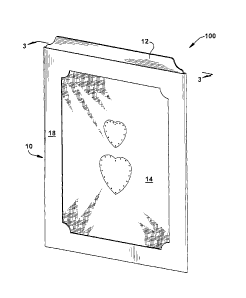
HG. 1 is a perspective view of a first embodiment of the greeting card of the
present
invention.
HG. 2 is an exploded view of the greeting card of FIG. 1.
HG. 3 is a rear tear-away view of the greeting card of FIG. 1 with the
removable panel in
a first position.
HG. 4 is a rear tear-away view of the greeting card of FIG. 1 with the
removable panel in
a second position.
HG. 5 is a side view of the greeting card of FIG. 3 from the perspective of
arrows 5-5.
HG. 6 is a side view of the greeting card of FIG. 4 from the perspective of
arrows 6-6.
HG. 7 is a perspective view of a second embodiment of the greeting card of the
present
invention, with the removable panel in a first position.
1
CA 02815587 2013-05-09
FIG. 8 is a perspective view of the greeting card of FIG. 7 with the removable
panel in a
second position.
FIG. 9 is a rear tear-away view of the greeting card of FIG. 8.
FIG. 10 is a side view of the greeting card of FIG. 9 from the perspective of
arrows 10-
10.
FIG. 11 is a side view of the greeting card of FIG. 7.
DETAILED DESCRIPTION OF PREFERRED AND ALTERNATE
EMBODIMENTS
The greeting card of the present disclosure and related inventions combines a
paper greeting card with fabric and fiber optics to create a visually
stimulating greeting
card.
In a first embodiment 100, shown in FIGS. 1 through 6, two or more greeting
card panels are combined to form a three sided pocket or cavity having an
opening along
a top edge of the pocket for insertion of a removable panel 12. The removable
panel 12,
in a first position (shown in FIG. 1), is substantially contained within the
greeting card
pocket 10, with a portion of the panel 12 visible, extending up through the
top open edge
of the pocket 10. In a second position (shown in FIG. 4), the removable panel
12 is
completely removed from the pocket 10. Removal of the removable panel 12
causes one
or more fiber optic strands 14, which are visible through the front of the
greeting card
pocket 10 to turn on or light up. As an example, the greeting card 100 may
contain three
greeting card panels which are attached along two fold lines. Each panel is of
a
substantially rectangular shape and all panels have approximately the same
length and
width, although in other embodiments, the panels may be of a different shape
and may
have varying length and/or width measurements. Each panel has a front surface
and a
back surface opposite the front surface. A first panel 22 is attached to a
second panel 18
along a first horizontal fold line and the second panel 18 is attached to a
third panel 20
along a second horizontal fold line. The second panel 18 contains a
substantial opening
thereon around which is a border or frame. The second panel 18 may also have
two tab
panels, a first tab panel attached to a right side long edge of the second
panel 18 and a
second tab panel attached to a left side long edge of the second panel 18. A
layer of
2
CA 02815587 2013-05-09
fabric 16 is placed over the back surface of the second panel 18 such that the
fabric 16
can be seen through the opening on the second panel 18. The fabric 16 is a
thin piece of
material which may contain various designs or patterns printed thereon. While
referred
to herein as "fabric" the material may be any type of woven, non-woven
material. A
fourth panel 24 or sheet material may be placed behind the fabric layer 16
such that the
fabric layer 16 is sandwiched between the second panel 18 and the fourth panel
24.
A fiber optic bundle 14 comprising one or more fiber optic strands connected
to
one or more LED light bulbs is located behind the fourth panel 24 opposite the
fabric
layer 16. The one or more fiber optic strands 14 are inserted through the
fourth panel 24
and the fabric layer 16 such that the fiber optics are visible through the
fabric 16 from the
opening in the second panel 18 of the greeting card 100. The fiber optic
bundle 14 may
be taped or otherwise secured behind the fourth panel 24. Also attached are
various
electronic components such as, but not limited to, a circuit board 26,
integrated circuit,
power source (one or more batteries) 28, a speaker 30, a switch 32 and any
other
component which facilitates illumination of the fiber optics upon some
triggering event.
Once the fiber optic bundle 14 and electronic components are secured behind
the second
18 and fourth panels 24 and the layer of fabric 16, the first panel 22, which
is connected
to the second panel 18 along a top horizontal edge, is folded downward along
the first
fold line such that it covers the fourth panel 24 and the fourth panel 24 and
fabric layer
16 are positioned between the second 18 and first panels 22. The first and
second tab
panels on the second panel 18 are folded over the first panel 22 to secure the
fabric 16
and fiber optic strand 14 therebetween. Finally, the third panel 20, which is
connected to
the second panel 18 along a second fold line along a bottom horizontal short
edge of the
second panel 18 is folded upward along the second fold line and attached,
adhesively or
otherwise, to the first and second tab panels of the second panel 18 so that
the second
panel 18 (which is the front of the greeting card) and the third panel 20
(which is the
back of the greeting card) form a three sided pocket or cavity with an opening
along the
top short edge of the greeting card 100.
In a preferred embodiment, the switch mechanism 32 is a contact switch. The
contact switch 32 may contain two contact arms that when in contact complete
an
electrical circuit. Separating the contact arms breaks the circuit. A
removable panel 12
3
CA 02815587 2013-05-09
is inserted into the greeting card 100 through the open top edge of the
cavity, and gets
inserted between the two arms of the contact switch 32 (shown in FIG. 5),
thereby
interrupting the circuit. The removable panel 12 may be a single panel or may
have to or
more panels, such as a two-paneled greeting card. Removal of the removable
panel 12
from the greeting card pocket or cavity removes the barrier between the two
contact arms
such that they are again in direct contact with each other (shown in FIG. 6),
thereby
completing the circuit and providing power to illuminate the one or more fiber
optic
strands visible through the fabric layer 16. Re-inserting of the removable
panel 12 into
the pocket or cavity and between the two arms of the contact switch 32
prevents power to
the fiber optics 14 and extinguishes the light. The fiber optics 14 may be
programmed to
blink, twinkle, or perform any other special light effects. The arms of the
contact switch
32 may be of any length, however, a longer length is preferred over a shorter
length, to
ensure proper placement of the removable panel 12 between the two arms of the
switch
32 as it is inserted into the pocket or cavity of the greeting card 100. The
removable
panel 12 may contain an opening thereon proximate to a top edge of the panel
12,
through which a ribbon or cord or other attachment device may be inserted. The
ribbon
or cord may be used by the greeting card recipient to remove the removable
panel 12
from the greeting card pocket.
In a second embodiment 200, shown in FIGS. 7 through 11, the greeting card has
at least two four-sided greeting card panels 36A, 36B which are attached along
three
outer perimeter edges, creating an open-ended cavity therebetween. While the
open
perimeter edge may be along any of the four perimeter edges, in a preferred
embodiment,
the open edge is the right vertical edge. A sound and light module are
contained within
the open ended cavity. The sound and light modules may be secured to one or
both the
panels 36A, 36B to ensure that they stay in place inside the cavity and cannot
be removed
from the open edge. As described above, the sound and light modules may
contain a
variety of electronic components which may include, but are not limited to: a
circuit
board 26, integrated circuit, a memory storage device, power source 28 (one or
more
batteries), one or more fiber optic strands 14, a speaker 30 and any other
component
which facilitates illumination of fiber optics 14 and/or playback of at least
one digital
audio recording upon some triggering event. A sliding panel 34 is contained
between the
4
CA 02815587 2013-05-09
at least two four-sided greeting card panels 36A, 36B, the sliding panel 34
being attached
to the greeting card (between the two panels 36A, 36B) at a pivot point 38,
wherein the
sliding panel 34 can be pivoted about the pivot point 38 from a first
position, wherein the
sliding panel 34 is substantially contained within the greeting card cavity
(shown in FIG.
7) and a second position, wherein the sliding panel 34 is rotated about the
pivot point 38
to be substantially outside of the greeting card cavity (shown in FIGS 8 and
9). A slide
or contact arm switch (described above) is contained within the greeting card
cavity and
works in combination with the sliding panel 34 to control illumination of the
fiber optics
14 and/or playback of at least one digital audio file stored on the sound
module. The
front and back panels 36A, 36B of the greeting card cavity may contain notched
areas
wherein a portion of the panel is removed. These notched portions serve to
make the
inner sliding panel 34 visible from the outside of the greeting card, as shown
in FIG. 7.
The sliding panel 34 may contain printing thereon containing the word "pull"
to direct
the user to pull the sliding panel 34 outside of the greeting card cavity and
initiate the
special effects such as lighting and/or sound. The front greeting card panel
36A contains
one or more openings or apertures 40 thereon through which the fiber optics 14
are
visible. A fiber optic bundle 14, as described above with regard to the first
embodiment
100, is contained in the greeting card cavity and may be taped therein such
that the end
portion of the fiber optic strands 14 are aligned with the openings 40 on the
front greeting
card panel 36A. Moving the inside sliding panel 34 from within the cavity
(shown in
FIG. 11) to outside the cavity (shown in FIG. 10), triggers the switch which
causes
illumination of the fiber optics 14 and/or playback of pre-recorded audio. The
pre-
recorded audio may contain music, a song, spoken word, or any other audible
sounds.
While this greeting card has been described as having two panels connected
along three
edges to form an open ended cavity, another panel may be inserted therein upon
which
the electronic components and/or fiber optic strands may be attached.
While the greeting cards of the present invention have been described herein
as
having a substantially rectangular or four sided shape, other greeting card
panel shapes
have been contemplated. Also, the various panels of the greeting card pocket
or cavities
are connected along various fold lines and folded in a particular manner
described herein,
however, any number of panels may be arranged in a variety of ways to contain
and
CA 02815587 2013-05-09
conceal the various electronic components and fiber optic bundle and to
display the
fabric layer with fiber optic strands extending therethrough. Also, other
electronic
components may be added to the present invention to provide further
entertainment for
the greeting card recipient, such as sound or music capabilities, recording
capabilities,
and other special effects. A contact switch is described herein to control
power to the
fiber optic strands, however, any other type of switch may be used, such as a
slide switch,
magnetic switch, light sensitive switch, touch sensitive switch or capacitance
switch, or
any other such switches which are known to one of skill in the art. The
embodiment
described herein was intended as an example only and is not meant to limit the
invention
in any way.
6