Note: Descriptions are shown in the official language in which they were submitted.
CA 02815643 2013-04-23
WO 2012/099535 PCT/SG2012/000003
Devices and Methods for Photoplethysmographic Measurements
BACKGROUND
Field of the Invention
[0001] This invention broadly relate to devices and methods for non-
invasive optical physiological measurements, including the detection of a
photoplethysmography (PPG) signal from a user, and more particularly to a
pressure detection assembly of an optical measurement device which detects an
amount of pressure applied by the user to the device.
Description of the Related Art
[0002] Optical monitoring of physiological characteristics utilizes the
detection of light transmitted through a location of a user being measured.
Photoplethysmography (PPG) is an optical measurement technique used to
detect blood volume changes in the microvascular bed of living tissue,
typically
by detecting light transmitted through the ear lobe or fingertip. As arterial
pulsations enter the capillary bed, changes in the volume of the blood vessels
or
characteristics of the blood itself modify the optical properties of the
capillary bed.
The PPG signal is used to measure saturation of peripheral oxygen (Sp02),
which is an estimation of the level of oxygen saturation in a fluid, such as
blood.
The PPG signal can also be used to measure blood pressure.
[0003] A device such as a pulse oximeter is an accepted standard in
clinical practice, and provides for measuring enhanced optical pulsatile
signals
1
CA 02815643 2013-04-23
WO 2012/099535
PCT/SG2012/000003
emitted by the changes in the volume of blood flowing through a user. The
pulse
oximeter generally has a pair of small light emitting diodes (LEDs) facing a
photodiode, with a translucent part of the user's body, usually a fingertip or
an
earlobe, positioned there between. The light from the LEDs passes through the
tissue and is detected by the photodiode. One LED is red, with wavelength of
approximately 660 nanometers (nm), and the other is infrared, with a
wavelength
of approximately 905, 910 or 940 nm. Absorption at these wavelengths differs
significantly between mryhemoglobin and its deoxygenated form. Therefore, the
ratio of oxyhemoglobin to deoxyhemoglobin can be calculated from the ratio of
the absorption of the red and infrared light, i.e. the ratio of red light to
infrared
light absorption of pulsating components at the measuring site.
[0004] The basic
form of PPG technology requires only a few
optoelectronic components: a light source to illuminate the tissue (e.g. skin)
and
a photodetector to measure the small variations in light intensity associated
with
changes in perfusion in a catchment volume.
[0005] The majority
of PPG devices currently available rely on simple
thresholding, or peak detection algorithms, to find principal peaks in a
detected
signal. However, these methods are typically unreliable when the detected
signal
is less than ideal. Particular problems may be encountered when the baseline
of
the AC signal component becomes noisy or complex, as can occur even with
mild movement artifacts.
2
CA 02815643 2013-04-23
WO 2012/099535
PCT/SG2012/000003
[0006] Hence, there
exists a need for an optical measurement device and
a method for detecting a physiological signal using an optical measurement
device that seek to address at least one of the above problems.
SUMMARY
[0007] There may be
provided an optical measurement device for
obtaining non-invasive physiological measurements from a portion of living
tissue
and method of using the same, which more particularly includes a pressure
detection assembly configured to detect and display an amount of pressure
applied by a body part of a user to the device during the optical measurement.
When a user applies an appropriate amount of pressure to the optical
measurement device, the resulting signal-to-noise ratio of the detected
optical
measurement signal, such as a photoplethysmography signal, can be increased,
and a more accurate measurement can be obtained from the user. An optimum
pressure can be determined in real-time by analyzing the detected optical
measurement signal and correlating a high signal-to-noise ratio portion of the
signal with a corresponding applied pressure. The user can be provided real-
time feedback indicating whether the amount of pressure being applied by the
user should be increased, decreased or maintained at the same level in order
to
continually obtain the highest quality signal. The optical measurement device
can facilitate providing an optimal pressure determination customized for each
individual user, thereby obtaining a resulting optimal measurement signal for
each user.
3
CA 02815643 2013-04-23
WO 2012/099535
PCT/SG2012/000003
[0008] In some
example embodiments, there is provided an optical
measurement device comprising an illumination and detection assembly
configured to output light to a portion of living tissue of a user and detect
transmitted or reflected light as a signal; a pressure assembly configured to
detect an amount of pressure applied to the illumination and detection
assembly
by the portion of living tissue of the user; and a feedback unit configured to
correlate the quality of the detected signal with the amount of applied
pressure
and provide feedback related to the correlation to the user.
[0009] The feedback
may be an indication of whether the user should
adjust the amount of pressure being applied to the illumination and detection
assembly.
[0010] The feedback
may display a range of optimal applied pressures
along with the actual applied pressure being applied by the user.
[0011] The range of
optimal applied pressures may correspond to a state
of zero transmural pressure.
[0012] The feedback
may be a request to the user to increase, decrease
or maintain the applied pressure.
[0013] The feedback
may be a real-time visual output of the detected
signal and detected applied pressure.
[0014] The feedback
unit may be a portable computer including a
processor, memory and a display.
[0015] The
illumination and detection assembly, pressure assembly and
feedback unit may be integrated into a portable device.
4
CA 02815643 2013-04-23
WO 2012/099535
PCT/SG2012/000003
[0016] The portable device may be configured with a plurality of
illumination and detection assemblies and a plurality of pressure assemblies.
[0017] The illumination and detection assembly and the pressure
assembly may communicate with the feedback unit over a wireless network.
[0018] The detected signal may be a photoplethysmography (PPG) signal.
[0019] In some example embodiments, a method for detecting a
physiological signal using an optical measurement device comprises:
illuminating
a portion of living tissue of a user and detecting transmitted or reflected
light as a
signal using an illumination and detection assembly; detecting an amount of
pressure applied by the portion of living tissue of the user to the
illumination and
detection assembly using a pressure detection assembly; correlating the
quality
of the detected signal with the amount of applied pressure; and providing
feedback related to the correlation to the user using a feedback unit.
- [0020] The method may include providing an indication to the user of
whether the amount of pressure being applied to the illumination and detection
assembly should be adjusted.
[0021] The method may include displaying a range of optimal applied
pressures along with the actual applied pressure being applied by the user.
[0022] The method may include providing a range of optimal applied
pressures along which corresponds to a state of zero transmural pressure.
[0023] The method may include requesting the user to increase, decrease
or maintain the applied pressure.
CA 02815643 2013-04-23
WO 2012/099535
PCT/SG2012/000003
[0024] The method may include displaying a real-time visual output of the
detected signal and the detected applied pressure.
[0025] The method may include providing feedback on a display of a
computer with a processor and a memory.
[0026] The illumination and detection assembly, pressure assembly and
feedback unit may be integrated into a portable device.
[0027] The portable device may be configured with a plurality of
illumination and detection assemblies and a plurality of pressure assemblies.
[0028] The method may include wirelessly communicating between the
feedback unit and the illumination and detection assembly and pressure
assembly.
[0029] The detected signal may be a photoplethysmography (PPG) signal.
[0030] In some example embodiments, a computer program product is
provided for detecting a physiological signal using an optical measurement
device, the computer program product embodied on a computer readable
medium and when executed by a computer with a processor and a memory,
performs the method comprising: illuminating a portion of living tissue of a
user
and detecting transmitted or reflected light as a signal using an illumination
and
detection assembly; detecting an amount of pressure applied by the portion of
living tissue of the user to the illumination and detection assembly;
correlating the
quality of the detected signal with the amount of applied pressure; and
providing
feedback related to the correlation to the user.
6
[0031] In accordance with an aspect, there is provided an optical
measurement
device comprising: an illumination and detection assembly comprising a light
emitting
diode, LED, configured to output light to a tissue portion of a user for
measurement and
a photodetector configured to detect the output light transmitted or reflected
from the
tissue portion of the user as a signal; a pressure detection assembly
configured to
detect an amount of pressure applied to the illumination and detection
assembly by the
user, the pressure detection assembly comprising a force sensor; wherein the
illumination and detection assembly and the pressure detection assembly are
configured to communicate with a feedback unit that is configured to correlate
a quality
of the detected signal with the amount of applied pressure by: computing an
area under
waveforms of detected signals corresponding to a variety of applied pressure
amounts,
and determining an optimum pressure to correspond to a largest computed area,
from
the variety of applied pressure amounts, wherein the pressure detection
assembly
further comprises a force transmitting member positioned to prevent light
emitted by the
LED from travelling directly to the photodetector.
[0032] The illumination and detection assembly and pressure assembly may
be
integrated into a single portable device and a feedback unit may be further
provided
separately.
[0033] The pressure assembly may not substantially deform or displace
when in
use.
[0034] The device may be a reflectance-based device.
[0035] The illumination and detection assembly may comprise a red light
emitting diode (LED), an infra-red LED or both.
7
CA 2815643 2018-01-12
CA 02815643 2015-07-29
[0036] Saturation of peripheral oxygen (SP02) information of the user may
be
derivable from the detected output light information from both the red LED and
the
infra-red LED.
[0037] The optical measurement device may further comprise a coupling
member configured for coupling in a cableless configuration to a personal
mobile
processing device.
[0038] The feedback unit may be configured to correlate the quality of the
detected signal with the amount of applied pressure and provide feedback
related to
the correlation to the user.
[0039] The illumination and detection assembly, pressure assembly and
feedback unit may be integrated into a portable device.
[0040] The personal mobile processing device may comprise the feedback
unit
configured to correlate the quality of the detected signal with the amount of
applied
pressure and provide feedback related to the correlation to the user.
[0041] The feedback may be an indication of whether the user should adjust
the amount of pressure being applied to the illumination and detection
assembly.
[0042] The feedback may display a range of optimal applied pressures along
with the actual applied pressure being applied by the user.
[0043] The range of optimal applied pressures may correspond to a state of
zero transmural pressure.
[0044] The feedback may be a request to the user to increase, decrease or
maintain the applied pressure.
8
[0045] The feedback may be a real-time visual output of the detected
signal and
detected applied pressure.
[0046] The feedback unit may be a portable computer including a processor,
memory and a display.
[0047] The portable device may be configured with a plurality of
illumination and
detection assemblies and a plurality of pressure assemblies.
[0048] The illumination and detection assembly and the pressure assembly
may
communicate with the feedback unit over a wireless network.
[0049] The detected signal may be a photoplethysmography (PPG) signal.
[0050] The personal mobile processing device may be one selected from a
group consisting of a mobile phone, a smartphone, a personal digital assistant
(PDA),
a mobile music player, a tablet computer, a netbook and a laptop.
[0051] In accordance with another aspect, there is provided a method for
detecting a physiological signal using an optical measurement device,
comprising:
illuminating, by a light emitting diode, LED, a tissue portion of a user for
measurement
and detecting, by a photodetector, transmitted or reflected output light from
the tissue
portion of the user as a signal using an illumination and detection assembly;
detecting
an amount of pressure applied by the user to the illumination and detection
assembly
using a pressure detection assembly comprising a force sensor; and correlating
a
quality of the detected signal with the amount of applied pressure by:
computing an
area under waveforms of detected signals corresponding to a variety of applied
pressure amounts, and determining an optimum pressure to correspond to a
largest
computed area, from the variety of applied pressure amounts, wherein the
pressure
9
CA 2815643 2018-01-12
detection assembly further comprises a force transmitting member positioned to
prevent light emitted by the LED from travelling directly to the
photodetector.
[0052] The illumination and detection assembly and pressure detection
assembly may be integrated into a single portable device and a feedback unit
may be
further provided separately.
[0053] The pressure assembly may not substantially deform or displace when
in
use.
[0054] The measurement device may be a reflectance-based device.
[0055] The illumination and detection assembly may comprise a red light
emitting diode (LED), an infra-red LED or both.
[0056] The method may further comprise deriving saturation of peripheral
oxygen (SP02) information of the user from the detected output light
information from
both the red LED and the infra-red LED.
[0057] The method may further comprise coupling a coupling member in a
cableless configuration to a personal mobile processing device.
[0058] The method may further comprise correlating the quality of the
detected
signal with the amount of applied pressure; and providing feedback related to
the
correlation to the user using the feedback unit.
[0059] The method may further comprise providing an indication to the user
of
whether the amount of pressure being applied to the illumination and detection
assembly should be adjusted.
CA 2815643 2018-01-12
CA 02815643 2015-07-29
[0060] The method may further comprise displaying a range of optimal
applied
pressures along with the actual applied pressure being applied by the user.
[0061] The method may further comprise displaying a range of optimal
applied
pressures along which corresponds to a state of zero transmural pressure.
[0062] The method may further comprise requesting the user to increase,
decrease or maintain the applied pressure.
[0063] The method may further comprise displaying a real-time visual output
of the detected signal and the detected applied pressure.
[0064] The feedback unit may be a portable computer including a processor,
memory and a display.
[0065] The illumination and detection assembly, pressure assembly and
feedback unit may be integrated into a portable device.
[0066] The portable device may be configured with a plurality of
illumination
and detection assemblies and a plurality of pressure assemblies.
[0067] The method may further comprise wirelessly communicating between
the feedback unit and the illumination and detection assembly and pressure
assembly.
[0068] The method may further comprise correlating the quality of the
detected
signal with the amount of applied pressure; and providing feedback related to
the
correlation to the user using a feedback unit; wherein the personal mobile
processing
device comprises the feedback unit.
[0069] The detected signal may be a photoplethysmography (PPG) signal.
11
[0070] In
accordance with yet another aspect, there is provided a computer
readable medium having stored thereon instructions for instructing a processor
of an
optical measurement device to execute a method for detecting a physiological
signal
using the optical measurement device, the method comprising: Illuminating, by
a light
emitting diode, LED, a tissue portion of a user for measurement and detecting,
by a
photodetector, transmitted or reflected output light from the tissue portion
of the user
as a signal using an illumination and detection assembly; detecting an amount
of
pressure applied by the user to the illumination and detection assembly using
a
pressure detection assembly which comprises a force sensor and a force
transmitting
member positioned to prevent light emitted by the LED from travelling directly
to the
photodetector; and correlating a quality of the detected signal with the
amount of
applied pressure by: computing an area under waveforms of detected signals
corresponding to a variety of applied pressure amounts, and determining an
optimum
pressure to correspond to a largest computed area, from the variety of applied
pressure amounts.
1 1 a
CA 2815643 2018-01-12
CA 02815643 2013-04-23
WO 2012/099535
PCT/SG2012/000003
[0071] The illumination
and detection assembly and pressure detection
assembly may be integrated into a single portable device and a feedback unit
may be further provided separately.
[0072] The pressure
assembly may not substantially deform or displace
when in use.
[0073] The illumination
and detection assembly may comprise a red light
emitting diode (LED), an infra-red LED or both.
[0074] The method of the
medium may further comprise deriving
saturation of peripheral oxygen (SP02) information of the user from the
detected
output light information from both the red LED and the infra-red LED.
[0075] The method of the
medium may further comprise correlating the
quality of the detected signal with the amount of applied pressure; and
providing
feedback related to the correlation to the user using the feedback unit.
[0076] In accordance
with yet another aspect of the present invention,
there is provided an accessory for a personal mobile processing device, the
accessory comprising a pressure assembly configured to detect an amount of
pressure applied to an illumination and detection assembly of the personal
mobile processing device by a surface portion of a user for measurement.
[0077] The pressure
assembly may not substantially deform or displace
when in use.
[0078] The accessory may
be removably attached to a casing for the
personal mobile processing device.
12
CA 02815643 2013-04-23
WO 2012/099535
PCT/SG2012/000003
[0079] The accessory may
be integrally attached to a casing for the
personal mobile processing device.
[0080] The personal
mobile processing device may be one selected from a
group consisting of a mobile phone, a smartphone, a personal digital assistant
(PDA), a mobile music player, a tablet computer, a netbook and a laptop.
[0081] Additional
aspects related to the invention will be set forth in part in
the description which follows, and in part will be apparent from the
description, or
may be learned by practice of the invention. Aspects of the invention may be
realized and attained by means of the elements and combinations of various
elements and aspects particularly pointed out in the following detailed
description
and the appended claims.
[0082] It is to be
understood that both the foregoing and the following
descriptions are exemplary and explanatory only and are not intended to limit
the
- claimed invention or application thereof in any manner whatsoever.
BRIEF DESCRIPTION OF THE DRAWINGS
[0083] The accompanying
drawings, which are incorporated in and
constitute a part of this specification, exemplify the embodiments of the
present
invention and, together with the description, serve to explain and illustrate
principles of the invention. Specifically:
[0084] FIG. 1 is an
illustration of a photoplethysmograph (PPG) and the
components thereof, as is conventional in the art;
13
CA 02815643 2013-04-23
WO 2012/099535
PCT/SG2012/000003
[0085] FIG. 2 is an
illustration of an AC pulse waveform of the PPG, as is
conventional in the art;
[0086] FIG. 3 is an
illustration of a cross-section of a blood vessel when a
low external pressure is applied;
[0087] FIG. 4 is an
illustration of the cross-section of the blood vessel
when a high external pressure is applied;
[0088] FIG. 5 is a
graphical illustration of an amplitude of a PPG signal
received during increasing amounts of external pressure in a state of zero
transmural pressure;
[0089] FIG. 6A is an
illustration of an optical measurement device,
according to an exemplary embodiment;
[0090] FIG. 6B is an
exploded view illustration of the optical measurement
device, including an illumination and detection assembly and a pressure
detection assembly, according to an exemplary embodiment;
[0091] FIGs. 7A and 7B
are expanded view illustrations of the illumination
and detection assembly and a pressure detection assembly of the optical
measurement device and a method of use with a human finger, and according to
one exemplary embodiment;
[0092] FIG. 8
illustrates a graphical comparison of a graph of measured
voltage of a PPG signal over time as it corresponds to a graph of an applied
amount of pressure over time;
14
CA 02815643 2013-04-23
WO 2012/099535
PCT/SG2012/000003
[0093] FIGs. 9A
and 9B illustrate a feedback unit, such as a portable
device with a display, in connection with an optical measurement device and a
user's interaction therewith, according to an exemplary embodiment;
[0094] FIG. 10
illustrates a graphical user interface (GUI) on the display,
including a graphical representation of a PPG signal and a graphical
representation of applied pressure, according to an exemplary embodiment;
[0095] FIG. 11
illustrates a portable device integrated with an optical
measurement device, according to an exemplary embodiment;
[0096] FIG. 12
illustrates an optical measurement device integrated with a
touchscreen display of a portable device, according to an exemplary
embodiment;
[0097] FIGs. 13A
and 13B illustrate a portable device connected with an
optical measurement device configured in a landscape orientation and a user's
- interaction therewith, according to an exemplary embodiment;
[0098] FIGs. 14A
and 14B illustrate a portable device integrated with a
plurality of optical measurement devices in a landscape orientation and a
user's
interaction therewith, according to an exemplary embodiment;
[0099] FIGs. 15A
and 158 illustrate a portable device integrated with a
plurality of optical measurement devices located on a side portion of the
portable
device, according to an exemplary embodiment;
[00100] FIGs. 16A
and 16B are expanded view illustrations of an alternate
embodiment of a method of using the optical measurement device with the
CA 02815643 2013-04-23
WO 2012/099535
PCT/SG2012/000003
human finger to detect the blood pressure of the human, according to one
exemplary embodiment;
[00101] FIG 17 is a
block diagram of the optical measurement device,
according to an exemplary embodiment;
[00102] FIGs 18A,
18B and 18C are graphical illustrations of signals used in
the process of obtaining a direct current (DC) component of the PPG signal,
according to an exemplary embodiment;
[00103] FIG. 19 is
an illustration of a sequence of data collection performed
during the process of obtaining the PPG signal, according to an exemplary
embodiment;
[00104] FIG. 20 is a
flow chart illustrating a method of measuring the PPG
signal on the optical measurement device using feedback from the pressure
detection assembly, according to an exemplary embodiment;
[00105] FIGs. 21A,
21B and 21C are graphical representations of the
correlation between a PPG waveform and an applied pressure, as would be used
in the method of measuring an optimal PPG signal, according to an exemplary
embodiment;
[00106] FIG. 22 is a
block diagram of a computer system upon which the
device and methods may be implemented, according to an exemplary
embodiment;
[00107] FIG. 23 is a
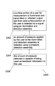
schematic flowchart illustrating a method for detecting
a physiological signal using an optical measurement device in an example
embodiment; and
16
CA 02815643 2013-04-23
WO 2012/099535
PCT/SG2012/000003
[00108] FIG. 24 shows a
simplified exemplary representative circuit
diagram for implementing a piezo-based sensing device in an example
embodiment.
[00109] FIG. 25A is a
cross-sectional view of a cantilever type optical
measurement device in accordance with another embodiment disclosed herein.
[00110] FIG. 25B is an
exploded view of the optical measurement device of
FIG. 25A.
[00111] FIG. 25C is a
simplified view of Fig. 25A showing only the main
components that may be useful for transmittance and sensing of an exerted
force.
[00112] FIG. 25D and FIG.
25E are schematics of an exemplary cantilever
type force application.
[00113] FIG. 25F is a
perspective view of the underside of the transparent
plastic piece and the top portion of the plastic housing of FIG. 25B.
[00114] FIG. 25G is an
exploded view of another exemplary embodiment of
the optical measurement device disclosed herein.
[00115] FIG. 25H is a
cross-sectional view of an assembled optical
measurement device of FIG. 25A at various levels of stripping to emphasize the
structure of the transparent plastic piece.
[00116] FIG. 251 is a
cross-sectional view of an assembled optical
measurement device of FIG. 25G, at various levels of stripping to emphasize
the
structure of the opaque or substantially opaque plastic piece.
17
CA 02815643 2013-04-23
WO 2012/099535
PCT/SG2012/000003
DETAILED DESCRIPTION
[00117] An optical
measurement device for obtaining non-invasive
physiological measurements and method of using the same is described more
fully herein, the device comprising a pressure detection assembly configured
to
detect an amount of pressure applied by a body part of a user to the device
during the optical measurement. When the user applies an appropriate amount
of pressure to the optical measurement device, the resulting signal-to-noise
ratio
of the detected optical measurement signal can be increased, and a more
accurate measurement signal can be obtained from the user. An optimal
pressure can be determined in real-time by analyzing the detected optical
measurement signal and correlating a high signal-to-noise ratio portion of the
signal with a corresponding applied pressure. The user can be provided real-
time feedback indicating whether the amount of pressure being applied by the
user should be increased, decreased or maintained at the same level. The
optical measurement device can therefore facilitate in providing an optimum
pressure determination customized for each individual user, thereby obtaining
a
resulting optimum measurement signal for each user.
[00118] The
description herein may be, in certain portions, explicitly or
implicitly described as algorithms and/or functional operations that operate
on
data within a computer memory or an electronic circuit. These algorithmic
descriptions and/or functional operations are usually used by those skilled in
the
information/data processing arts for efficient description. An algorithm is
generally relating to a self-consistent sequence of steps leading to a desired
18
CA 02815643 2013-04-23
WO 2012/099535
PCT/SG2012/000003
result. The algorithmic steps can include physical manipulations of physical
quantities, such as electrical, magnetic or optical signals capable of being
stored,
transmitted, transferred, combined, compared, and otherwise manipulated.
[00119] Further,
unless specifically stated otherwise, and would ordinarily
be apparent from the following, a person skilled in the art will appreciate
that
throughout the present specification, discussions utilizing terms such as
"scanning", "calculating", "determining", "replacing", "generating",
"initializing",
"outputting", and the like, refer to action and processes of a instructing
processor/computer system, or similar electronic circuit/device/component,
that
manipulates/processes and transforms data represented as physical quantities
within the described system into other data similarly represented as physical
quantities within the system or other information storage, transmission or
display
devices etc.
[00120] The
description also discloses relevant device/apparatus for
performing the steps of the described methods. Such apparatus may be
specifically constructed for the purposes of the methods, or may comprise a
general purpose computer/processor or other device selectively activated or
reconfigured by a computer program stored in a storage member. The algorithms
and displays described herein are not inherently related to any particular
computer or other apparatus. It is understood that general purpose
devices/machines may be used in accordance with the teachings herein.
Alternatively, the construction of a specialized device/apparatus to perform
the
method steps may be desired.
19
CA 02815643 2013-04-23
WO 2012/099535
PCT/SG2012/000003
[00121] In addition, it is
submitted that the description also implicitly covers
a computer program, in that it would be clear that the steps of the methods
described herein may be put into effect by computer code. It will be
appreciated
that a large variety of programming languages and coding can be used to
implement the teachings of the description herein. Moreover, the computer
program if applicable is not limited to any particular control flow and can
use
different control flows without departing from the scope of the invention.
[00122] Furthermore, one
or more of the steps of the computer program if
applicable may be performed in parallel and/or sequentially. Such a computer
program if applicable may be stored on any computer readable medium. The
computer readable medium may include storage devices such as magnetic or
optical disks, memory chips, or other storage devices suitable for interfacing
with
a suitable reader/general purpose computer. The computer readable medium
may even include a wired medium such as exemplified in the Internet system, or
wireless medium such as exemplified in bluetooth technology. The computer
program when loaded and executed on a suitable reader effectively results in
an
apparatus that can implement the steps of the described methods.
[00123] The example
embodiments may also be implemented as hardware
modules. A module is a functional hardware unit designed for use with other
components or modules. For example, a module may be implemented using
digital or discrete electronic components, or it can form a portion of an
entire
electronic circuit such as an Application Specific Integrated Circuit (ASIC).
A
CA 02815643 2013-04-23
WO 2012/099535
PCT/SG2012/000003
person skilled in the art will understand that the example embodiments can
also
be implemented as a combination of hardware and software modules.
[00124] In the
following detailed description, reference will be made to the
accompanying drawings. The aforementioned accompanying drawings show by
way of illustration and not by way of limitation, specific embodiments and
implementations consistent with principles of the present invention. These
implementations are described in sufficient detail to enable those skilled in
the art
to practice the invention, and it is to be understood that other
implementations
may be utilized and that structural changes and/or substitutions of various
elements may be made without departing from the scope and spirit of present
invention. The following detailed description is, therefore, not to be
construed in
a limited sense. Additionally, the various embodiments of the invention as
described may be implemented in the form of software running on a general
purpose computer, in the form of a specialized hardware, or combination of
software and hardware.
[00125] In the
following description, it will be appreciated that the optical
measurement device described can be, but is not limited to, a reflectance-
based
measurement device. In some example embodiments, saturation of peripheral
oxygen (SP02) information of a user is derivable from detected output light
information from both a red LED and an infra-red LED. In some example
embodiments, the measurement device can function as an accessory to a
personal mobile processing device.
21
CA 02815643 2013-04-23
WO 2012/099535
PCT/SG2012/000003
[00126] Further, in
the description herein, the term "light" as used herein is
meant to be interpreted in a broad sense and is not limited to visible light
only.
The term "light" as used herein can include, but is not limited to, X-ray
light rays,
visible light rays, ultraviolet light rays and infra-red light rays.
[00127] FIG.1 and
FIG. 2 are provided to briefly describe components of a
PPG signal. FIG. 1 illustrates a graphical representation of a
photoplethysmograph (PPG) signal 100, which can generally be divided into two
components: an AC component 102 due to the absorption of light in pulsatile
arterial blood volume 106; and a DC component 104 caused by the absorption
produced by non-pulsatile arterial blood ¨ i.e. venous blood and capillary
blood
108, and tissue absorption 110.
[00128] In FIG. 1,
this AC component 102 is superimposed onto a large
quasi-DC component 104 that relates to the tissues and to the average blood
volume. This DC component 104 varies slowly due to respiration, vasomotor
activity and vasoconstrictor waves. With suitable electronic filtering and
amplification, both the AC component 102 and DC component 104 can be
extracted for subsequent pulse wave analysis.
[00129] Two
significant characteristics of the PPG AC pulse waveform 102
have been described and are illustrated in FIG. 2, where the appearance of the
pulse waveform was defined as two phases: a first anacrotic phase 112 being
the
rising edge of the pulse, and a second catacrotic phase 114 being the falling
edge of the pulse. The first phase 112 is primarily concerned with systole,
while
the second phase 114 represents diastole and wave reflections 116 from the
22
CA 02815643 2013-04-23
WO 2012/099535
PCT/SG2012/000003
periphery. A dicrotic notch 118 is usually seen in the second catacrotic phase
114 of subjects with healthy compliant arteries.
[00130] As
discussed, the acquisition of a physiological signal representing
a change in the volume of an organ in the body through the use of optical
measurement is known as a photoplethysmograph (PPG). Obtaining optical
PPG signals typically requires application of external pressure on the body
surface which is being measured. The pressure correlates to obtaining a good
quality PPG signal with a high signal to noise ratio.
[00131] However, the
externally-applied pressure cannot be too large or too
small, or the quality of the detected PPG signal will be low. For example, as
illustrated in a cross section of a blood vessel 300 in FIG. 3, in the event
of an
insufficient exertion of external force as compared to internal arterial
pressure at
a measurement site 302, the internal pressure is too low to obtain a proper
measurement, and low PPG signals are obtained. On the contrary, as illustrated
in FIG. 4, the application of too much external force causes the blood vessel
300
to be occluded at the measurement site 302 where the pressure is applied,
resulting in resistance of regular blood flow and generating skewed PPG signal
data. If the external pressure is too small or too high, the reaction pressure
at
the wall of the blood vessel 300 is low, and thus a small PPG signal will be
observed. FIG.5 is a graphical illustration of the amplitude 502 of a measured
PPG signal in comparison with an amount of applied external pressure. With a
low applied pressure in range A, the amplitude 502 is correspondingly low. As
the applied pressure is increased, in range B, the amplitude also increases.
23
CA 02815643 2013-04-23
WO 2012/099535
PCT/SG2012/000003
However, when the applied pressure increases beyond a certain point, the
amplitude decreases again, as shown in range C.
[00132] To obtain a
strong PPG signal, the external pressure should be
sufficient to minimize transmural pressure such that the external pressure is
equal to the internal pressure. Further illustrated in FIG. 5 is a range 504
within
range B where the amplitude of the PPG signal is at its peak. Within this
range
504, an externally-applied pressure is instantaneously balanced with the
internal
arterial pressure, thus resulting in a state of zero transmural pressure. At
zero
transmural pressure, the arterial walls are unloaded and the arteries will not
change in size. Consequently, the blood volume within the arteries at the
measured region will not change and can be accurately measured to provide a
good quality PPG signal.
[00133] In an
exemplary embodiment, the pressure assembly assists in
- achieving and maintainingan optimal pressure for obtaining an optimum PPG
signal over an extended period of time. Preferably, by providing real-time,
instantaneous feedback to a user being measured, the user can be able to
instantly adjust the amount of pressure being applied to the device in order
to
obtain an optimum PPG signal. However, the optimum pressure may not only be
a result of a state of zero transmural pressure, but may also result from the
effects of absorption and scattering paths of light as light travels in and
out of a
portion of tissue of a user being measured. For example, where the pressure is
too low, a light source may not be able to penetrate the tissue surrounding
the
blood vessel which is being measured. Therefore, light may not travel in and
out
24
CA 02815643 2013-04-23
WO 2012/099535
PCT/SG2012/000003
of the finger effectively enough for a good PPG signal to be detected. Where
the
pressure is too high, light may be absorbed or scattered such that the amount
of
light detected is insufficient to obtain a good PPG signal.
[00134] In one
exemplary embodiment, the device may assist in providing
feedback to the user indicating whether the user is applying insufficient
pressure,
too much pressure or the correct amount of pressure. The feedback to the user
may be visual or auditory in the form of a visual display or audible sounds,
and
may particularly be a display of the real-time PPG signal being captured by
the
device. The feedback may also be a more simplified display indicating whether
the user should take action to increase or reduce the amount of pressure being
applied to the device. In another embodiment, the feedback may be in the form
of
tactile feedback, wherein the device produces e.g. a small vibration when the
applied pressure is at an optimum range.
[00135] Exemplary
embodiments described herein seek to provide a device
and method capable of augmenting signal to noise ratio in an optical signal of
an
illuminated region at a measuring site of a body part of a user. Exemplary
embodiments also provide for detecting the optical response formed by both
light
reflected from the measuring site and the light transmitted through the
measuring
site. Exemplary embodiments described herein utilize redirecting reflections
of
light on its way towards the measuring site (i.e. blood vessels) back to the
region
of interest.
[00136] In an
additional exemplary embodiment, the device may perform a
series of calibration steps for each individual user in order to determine an
CA 02815643 2013-04-23
WO 2012/099535
PCT/SG2012/000003
optimum range of pressure for each individual. The subsequent steps of
capturing the PPG signal will then use the predetermined optimum range as the
benchmark for obtaining an optimum PPG signal.
I. Device Overview
[00137] FIG. 6A
illustrates one exemplary embodiment of an optical
measurement device 600, and FIG. 6B illustrates an exploded view of the
optical
measurement device 600, showing the arrangement of an illumination and
detection assembly 602 and a pressure detection assembly 604. As illustrated
in
FIG. 6A, the illumination and detection assembly 602 and pressure detection
assembly 604 may be integrated as a single, compact optical measurement
device 600 surrounded by a housing 601 for portable use. In the exploded view
in FIG. 6B, the housing 601 is shown divided into a top casing 603 and a base
casing 605, with the illumination and detection assembly 602 and pressure
detection assembly 604 enclosed therein. The integration of the pressure
detection assembly 604 with the illumination and detection assembly 602
provides a simple, comfortable interaction for the user. In one embodiment,
the
pressure detection assembly 602 comprises non-movable parts such that the
pressure detection assembly 602 does not employ spring/elastic force and does
not substantially deform or displace when in use. That is, when an external
pressure or force is applied by the user to the pressure detection assembly,
the
pressure detection assembly does not substantially deform or displace. The use
of a pressure detection assembly 604 in cooperation with e.g. an external
feedback unit can provide real-time feedback to the user that improves the
26
CA 02815643 2013-04-23
WO 2012/099535
PCT/SG2012/000003
quality, or amplitude, of the received PPG signals. The optical measurement
device 600 is connected with a feedback unit 606 (see FIG. 9A), which receives
the PPG signals and pressure measurements from the optical measurement
device 600 and provides feedback to the user regarding the amount of pressure
being applied. Accordingly, in this embodiment, the feedback unit 606 can be
provided separately from the optical measurement device 600.The illumination
and detection assembly 602 may be referred to as a PPG sensor, and includes a
light source 608 and a plurality of light detectors 610 (see FIG. 17), where
the
light source 608 propagates light through a portion of living tissue at a
measurement site of a user. The light detectors 610 then detect light which is
transmitted through the portion of living tissue of the user or which is
reflected
from the portion of living tissue of the user.ln one exemplary embodiment, the
pressure detection assembly 604 is a pressure sensor that detects the amount
of
pressure that has been applied by a body part of the user, such as a finger.
The
pressure sensor may be a thin film flexible printed circuit, such as a piezo-
based
or piezoresistive sensing device whereby a resistance change sensed by the
circuitry is inversely proportional to a change in force applied on the
sensing
device. In some example embodiments, the circuit is a micro-electro-mechanical
(MEMS) strip. Nevertheless, any other force measuring device that is capable
of
sensing an applied contact force may be used. Preferably, the pressure sensor
comprises non-movable parts, does not employ spring/elastic force and does not
substantially deform or displace when in use.
27
CA 02815643 2013-04-23
WO 2012/099535
PCT/SG2012/000003
[00138] In certain
embodiments, the pressure detection assembly of the
optical measurement device may comprise a cantilever means coupled to a force
transmitting member for transmitting an exerted force by a cantilever moment
to
the force transmitting member. The cantilever means may be a beam-like
structure supported by at least one fulcrum. In one embodiment, when in use,
the
fulcrum is disposed at one end of the beam-like structure. The cantilever
means
may also comprise a mating means that is capable of mating with a
complementary matching means of a housing of the optical measurement device.
The mating means of the cantilever means may be any physical feature that is
capable of mating with the matching means of the housing so that the
cantilever
means can fit snugly within the housing. Likewise, the matching means of the
housing may be any physical feature that is capable of mating with the mating
means of the cantilever means to provide secure engagement therewith. In one
- embodiment, the mating means comprises one or more features selected from
the group consisting of a protrusion, projection, abutment, extension and the
like,
while the matching means comprises one or more features selected from the
group consisting of a hole, slot depression, recess, opening, aperture and the
like. In another embodiment, the matching means comprises one or more
features selected from the group consisting of a protrusion, projection,
abutment,
extension and the like, while the mating means comprises one or more features
selected from the group consisting of a hole, slot, depression, recess,
opening,
aperture and the like. Preferably, both the mating means and matching means
are stepped structures that are complementary to each other. In other
28
CA 02815643 2013-04-23
WO 2012/099535
PCT/SG2012/000003
embodiments, the cantilever means may be part of the force transmitting
member and vice versa such that both the cantilever means and the force
transmitting member form a single unitary structure.
[00139] FIG. 25A is
a cross-sectional view of a cantilever type optical
measurement device in accordance with another embodiment disclosed herein.
The optical measurement device 2500 comprises a wave emitter in the form of a
light emitting diode 2502 and a wave detector in the form of a photodetector
2504
disposed on the same horizontal plane (relative to the sensing device base)
and
on the same substrate, which is in the form of a printed circuit board 2512.
The
wave emitter and the wave detector may be part of the illumination detection
assembly. The substrate or printed circuit board 2512 further comprises an
opening 2520 disposed between the LED 2502 and photodetector 2504. A force
transmitting member comprising a plastic assembly piece 2506 and an overhead
portion 2508, is arranged such that the plastic assembly piece 2506 extends
through the opening 2520, between the light emitting diode 2502 and the
photodetector 2504. The force transmitting member may be part of a pressure
assembly. The overhead portion 2508 is provided to increase the overall
surface
area available to substantially prevent light emitted by the LED 2502 from
travelling directly to the photodetector 2504. In this exemplary embodiment,
the
overhead portion 2508 is inserted into the plastic assembly piece such that
both
of them fit snuggly with each other. The overhead portion 2508 can also be
provided in other forms, shapes and/or orientation so long as it serves to
substantially prevent light emitted by the LED 2502 from travelling directly
to the
29
CA 2815643 2017-04-04
photodetector 2504. The overhead portion 2508 can be a detachable portion that
is
attached to the plastic assembly piece 2506. Alternatively, the overhead
portion 2508
can be a continuous part of the plastic assembly piece 2506 formed as a single
structure. The plastic assembly piece 2506 is opaque and substantially does
not allow
light from the light emitting diode 2502 to travel directly to the
photodetector 2504. The
overhead portion 2508 is also opaque. However, the overhead portion 2508
comprises access hole 2508a for allowing light emitted from the light emitting
diode
2502 to pass through and access hole 2508b for allowing reflected light to
pass
through to reach the photodetector 2504. As can be seen in Fig 25A, the force
transmitting member 2506 as a whole appears to have a forked shaped cross
sectional area to allow the overhead portion 2508 to rest thereon. The forked
shaped
cross sectional area provides stability to the overhead portion 2508 and also
facilitates
transmission of an exerted force via a cantilever type moment. From the side
view, the
forked shape cross sectional area appears to comprise a base having a
plurality of
walls (for e.g. two walls) extending from the base such that the walls are
substantially
perpendicular to the base. From the side view, the walls are spaced at a
distance from
each other. From a three-dimensional perspective, the force transmitting
member
2506 can in fact be a circumferential wall extending from a base having the
forked
shaped cross sectional area described above. The circumferential wall may be
continuously joined such that it forms a enclosure around a space on the base
(as
shown for example in component 2506 of FIG 25B). The circumferential wall can
be
annular shaped or in any other shape as long as it forms an
CA 2815643 2017-04-04
enclosure around a space on the base. In other embodiments, it is also
possible that
the circumferential wall comprises one or more gaps to disrupt its continuity
but may
nevertheless still be considered to generally surround a space on the base.
Due to the
wall/s extending from the base, the space on the base that is surrounded by
the wall/s
may be deemed as a recess or cavity. In some other cases, the walls may be
deemed
as a built up area around the space on the base. The overhead portion 2508 can
have
a protrusion 2508c that is complementary to this recess or cavity such that
the
protrusion of the overhead portion 2508 can be inserted into the recess or
cavity
2506a within the plastic assembly piece 2506 to provide a more snug or rigid
fit. It will
be appreciated that in some exemplary embodiments this complementary mating
structure may be reversed such that the recess or cavity now exists on the
overhead
portion and the protrusion exists on the force transmitting member.
[00140] The
positioning and the structure of the force transmitting member 2506
substantially prevents light emitted by the light emitting diode 2502 from
traveling
directly to the photodetector 2504. The force transmitting member is rested on
a
sensing substrate in the form of force sensor 2518. The force sensor 2518 can
be
provided as a flexible printed circuit that senses contact force and provides
the
associated electrical signal to the printed circuit board 2512 via the
electrical
connectors at one end of the force sensor 2518 (not shown in FIG 25A.). Due to
its
flexibility, the force sensor 2518 is able to deform slightly when the force
transmitting
member transmits a force to the metal connector 2518. The optical measurement
device 2500 also comprises a plastic housing 2514 for
31
CA 02815643 2013-04-23
WO 2012/099535
PCT/SG2012/000003
housing the individual components described above. At the top of the housing
2514, there is provided an orientation-free measurement surface in the form of
a
transparent plastic piece 2510 for receiving a surface portion of the user to
be
detected. The orientation-free measurement surface in the form of the
transparent plastic piece 2510 is not limited to a single orientation at which
the
surface portion of the user must be placed. For example, as compared to a clip
or a cuff, the orientation-free measurement surface does not require the
surface
portion of the user to be engaged therewith in a particular fashion, so long
as the
user surface in contact with the orientation-free measurement surface is
capable
of reflecting the emitted waves towards the wave detector. As such, the
orientation-free measurement surface is capable of advantageously detecting a
2-dimensional surface. On the other hand, the portion of the user to be
detected
must be 3-dimensional when a clip or a cuff is used, in order to ensure
sufficient
engagement with the clip or the cuff for detection. The transparent plastic
piece
2510 may further provide an additional layer of protection, to prevent direct
contact and damage to the LED and photodetector. It may also serve to prevent
dust and small particles from entering the housing of the sensing device.
[00141] In this
exemplary embodiment, the optical measurement device
2500 also comprises a coupling member in the form of a data communication
port 2516 electrically coupled to the printed circuit board 2512. The data
communication port 2516 is capable of transmitting electrical signals to and
from
the sensing device 2500. The data communication port 2516 is also capable of
transmitting electrical power to power the printed circuit board 2512 and its
32
CA 02815643 2013-04-23
WO 2012/099535
PCT/SG2012/000003
electrically connected components such as the light emitting diode 2502 and
the
photodetector 2504 and force sensor 2518.
[00142] In use, the
sensing device 2500 can be connected to a personal
mobile processing unit for example a mobile phone via the data communication
port 2516. The user then places a desired surface to be detected, for example
a
finger, onto the transparent plastic piece 2510. Light emitted from the light
emitting diode 2502 travels through the access hole 2508a and towards the
finger surface in contact with the transparent plastic piece 2510. The emitted
light
that is reflected from the finger surface passes through access hole 2508b and
towards the photodetector 2504. The photodetector 2504 then transmits an
electrical signal representative of the detected reflected light to the mobile
phone
via the data communication port 2516. A cover 2516A may be provided for the
data communication port 2516. At the same time, the exerted force is
transmitted
via the plastic assembly piece 2506 towards the force detector 2518. The force
detector 2518 then provides an electrical signal representative of the force
with
the circuit board 2512. The electrical signal is then transmitted to the
mobile
phone via the data communication port 2516. The mobile phone may comprise a
processing unit to process the signals received from the optical measurement
device 2500. The mobile phone may also comprise a feedback unit to indicate to
the user whether the force exerted by the finger is too high or low. The user
may
then adjust the force or pressure accordingly and once the optimum pressure is
detected, the mobile phone will display the physiological characteristics that
are
derived from the properties of the reflected light detected.
33
CA 02815643 2013-04-23
WO 2012/099535
PCT/SG2012/000003
[00143] FIG. 25B is
an exploded view of the sensing device of FIG. 25A.
The individual components are dismantled and can be clearly seen. The plastic
housing 2514 can be seen to be separated into a top portion 2514a and a bottom
portion 2514b. The force sensor 2518 senses contact force and provides the
associated electrical signal to the printed circuit board 2512 via the
electrical
connectors 2519 at one end of the force sensor 2518.
[00144] FIG. 25C is
a simplified view of Fig. 25A showing only the main
components that may be useful for the transmission and the sensing of an
exerted force through a cantilever type moment. The cantilever structure can
restrict movement of the column in all direction except one. This can give the
column better stability and easy for user to maintain a constant applied
force.
[00145] FIG. 25D and
FIG. 25E show schematics of an exemplary
cantilever type force application 2530. Component 2534 can be taken to be a
simplified representation of the transparent plastic piece 2510 together with
the
overhead portion 2508 of FIG 25B, Component 2536 can be taken to be a
simplified representation of the force transmitting member 2506 of FIG 25B,
and
Component 2540 can be taken to be a simplified representation of the force
detector 2518 of FIG 25B. When force F is applied on Component 2534 towards
Component 2536, a bending moment occurs resulting in deformation of
Component 2534 and Component 2536 towards one direction. This bending
moment is transmitted to Component 2540 for detection.
[00146] FIG. 25F is
a perspective view of the underside of the transparent
plastic piece 2510 and the top portion of the plastic housing 2514a of FIG.
25B.
34
CA 02815643 2013-04-23
WO 2012/099535
PCT/SG2012/000003
As shown in FIG. 25F, the transparent plastic piece 2510 comprises protrusions
2510a that are able to fit into the access holes 2508a and 2508b of the
overhead
portion 2508 of FIG. 25B in order to secure and prevent undesirable lateral
movement of the transparent plastic piece 2510.
[00147] FIG. 25G is
an exploded view of another exemplary embodiment of
an optical measurement device 2550 disclosed herein. In this exemplary
embodiment, most of the components are similar to those described in FIG 25B.
These similar elements are labelled with the same reference numerals used in
FIG. 25B but with the inclusion of the prime symbol . In this exemplary
embodiment, the main differences from the embodiment of FIG. 25B are the
components 2552 and 2554. Component 2552 is a plastic piece that is opaque or
substantially opaque (allows minimal light to pass through) but has access
holes
2552a to allow light to pass through. Component 2554 is an overhead portion
- similar to the overhead portion 2508 of FIG. 26. However, component 2554 is
substantially transparent which can allow light to pass through. Further,
protrusions 2554a (which are also transparent), are present instead of the
access
holes 2508a and 2508b shown in FIG. 25B. The protrusion 2554a are able to fit
into the access holes 2552a of the opaque or substantially opaque plastic
piece
2552 in order to secure and prevent undesirable lateral movement of the
plastic
piece 2552. It will be appreciated that this configuration is reversed from
that
shown in FIG. 25F.
[00148] FIG. 25H is
a cross-sectional view of an assembled sensing device
of FIG. 25A at various levels of stripping to emphasize the structure of the
CA 02815643 2013-04-23
WO 2012/099535
PCT/SG2012/000003
transparent plastic piece. As shown in FIG. 25H, the transparent piece 2510
has
a fulcrum end 2511a that fits snugly into the casing 2514, such that lateral
movements in the plane defined by the X and Y coordinate axes (the Y axis
being the axis going into the page and the X axis being the axis going from
the
left to the right of the page from the viewer's perspective) are restricted.
The
opposite end 2511b is free to move downwards along the Z coordinate axis (the
Z axis being the axis going from bottom to top of the page from the viewer's
perspective). However, the transparent piece 2510 has a stepped outer edge
such that the bottom surface is wider than its top surface. The casing 2514 is
correspondingly dimensioned to only fit the smaller top surface, but not the
bottom surface. Therefore, because the larger bottom surface is restricted
from
moving out of the casing surface, upward movement of the cantilever
transparent
piece cannot exceed the default position. When attempts are made to move the
cantilever transparent piece 2510 upwards, the stepped edge at the opposite
end
2511b engages with a complementary stepped edge of casing 2514, thus
arresting upward movement from its predetermined position. This can prevent
the transparent piece 2510 from falling out of the casing 2514 and can also
allow
the measurement of an accurate default pressure, where no external force is
applied. In certain embodiments, a resilient means such as a spring can be
coupled to the stepped edge at the opposite end 2511b to return it to its
original
configuration when a user exerted downward force on it is removed. The
resilient
means can also urge the stepped edge at the opposite end 2511b towards the
casing 2514 for engagement thereto, when the user exerted force on opposite
36
CA 02815643 2013-04-23
WO 2012/099535
PCT/SG2012/000003
end is removed. When fully assembled, the fulcrum end 2511a of the transparent
plastic piece 2510 (acting as a cantilever) can sit on top of the
communication
port 2516, as shown in FIG. 25H. In certain embodiments, a resilient means
such
as a spring can be present between the transparent plastic piece 2510 and the
communication port 2516. It can be seen in FIG. 25H that the transparent
plastic
piece 2510 is perched at the end of the communication port 2516 such that part
of 2511a is free and not in contact with the communication port 2516. This can
possibly allow some clockwise rotation (from the viewer's perspective of FIG.
25H) of the plastic piece 2510 when a force is applied at the opposite end. As
the
transparent plastic piece 2510 can also act as a cantilever, the transparent
plastic piece 2510 can be substantially flexible but at the same time have
sufficient flexural strength to withstand the force exerted by the user during
a
PPG measurement. The transparent plastic piece 2510 may also have sufficient
- flexural strength and/or elasticity to return it back to its original
shape/position
when the exerted force is removed. In some other exemplary embodiments, the
transparent plastic piece 2510 may be coupled to a resilient means such as a
spring which returns the transparent plastic piece 2510 back to its original
configuration once the exerted force is removed. With complementary mating
structures present among the different components, it will be appreciated that
the
exemplary sensing device can be easily assembled to form a rigid and stable
assembly which arrests undesired movement. This can allow the sensing device
to have a high level of measurement accuracy and consistency by reducing the
number of unknown or variable parameters present (for e.g. caused by undesired
37
CA 02815643 2013-04-23
WO 2012/099535
PCT/SG2012/000003
movement of the components). Another advantage of the complementary mating
structures would be that the individual components can be reversibly assembled
or disassembled from each other, making repairs or replacement of the
individual
components convenient. It will also be appreciated that the exemplary sensing
device with its individual complementary mating structures can be adapted into
a
snap-fit design for easier assembly and disassembly.
[00149] FIG. 251 is
a cross-sectional view of an assembled sensing device
of FIG. 25G , at various levels of stripping to emphasize the structure of the
opaque or substantially opaque plastic piece. As shown in FIG. 251, the
plastic
piece 2552 has a fulcrum end 2553a that fits snugly into the casing 2514',
such
that lateral movements in the plane defined by the X and Y coordinate axes
(the
Y axis being the axis going into the page and the X axis being the axis going
from the left to the right of the page from the viewer's perspective) are
restricted.
The opposite end 2553b is free to move downwards along the Z coordinate axis
(the Z axis being the axis going from bottom to top of the page from the
viewer's
perspective). However, the plastic piece 2552 has a stepped outer edge such
that the bottom surface is wider than its top surface. The casing 2514' is
correspondingly dimensioned to only fit the smaller top surface, but not the
bottom surface. Therefore, because the larger bottom surface is restricted
from
moving out of the casing surface, upward movement of the cantilever piece
cannot exceed the default position. When attempts are made to move the
cantilever plastic piece 2552 upwards, the stepped edge at the opposite end
2553b engages with a complementary stepped edge of casing 2514', thus
38
CA 02815643 2013-04-23
WO 2012/099535
PCT/SG2012/000003
arresting upward movement from its predetermined position. This can prevent
the plastic piece 2552 from falling out of the casing 2514' and can also allow
the
measurement of an accurate default pressure, where no external force is
applied
by the user. In certain embodiments a resilient means such as a spring can be
coupled to the stepped edge at the opposite end 2553b to return it to its
original
configuration when a user exerted downward force on it is removed. The
resilient
means can also urge the opposite end 2553b towards the casing 2514' for
engagement thereto, when the user exerted force on the opposite end 2553b is
removed. The cantilever piece 2552 comprises a further center protrusion 2552b
which can extend through an opening 2554b (See Fig. 25G) of the overhead
transparent piece 2554 and be inserted into a complementary recess or cavity
within the plastic assembly piece 2506' to provide a more snug or rigid fit.
When
fully assembled, the fulcrum end 2553a of the plastic piece 2554 (acting as a
cantilever) can sit on top of the communication port 2516', as shown in FIG.
251.
In certain embodiments a resilient means such as a spring can be present
between the plastic piece 2552 and the communication port 2516'. It can be
seen
in FIG. 251 that the transparent plastic piece 2552 is perched at the end of
the
communication port 2516' such that part of 2553a is free and not in contact
with
the communication port 2516'. This can possibly allow some clockwise rotation
(from the viewer's perspective of FIG. 251) of the plastic piece 2552 when a
force
is applied at the opposite end. As the plastic piece 2552 can also act as a
cantilever, the plastic piece 2552 can be substantially flexible but at the
same
time have sufficient flexural strength to withstand the force exerted by the
user
39
CA 02815643 2013-04-23
WO 2012/099535
PCT/SG2012/000003
during a PPG measurement. The plastic piece 2552 may also have sufficient
flexural strength and/or elasticity to return it back to its original
shape/position
when the exerted force is removed. In some other exemplary embodiments, the
plastic piece 2552 may be coupled to a resilient means such as a spring which
returns the plastic piece 2552 back to its original configuration once the
exerted
force is removed. With complementary mating structures present among the
different components, it will be appreciated that the exemplary sensing device
can be easily assembled to form a rigid and stable assembly which arrests
undesired movement. This can allow the sensing device to have a high level of
measurement accuracy and consistency by reducing the number of unknown or
variable parameters present (for e.g. caused by undesired movement of the
components). Another advantage of the complementary mating structures would
be that the individual components can be reversibly assembled or disassembled
from each other, making repairs or replacement of the individual components
convenient. It will also be appreciated that the exemplary sensing device with
its
individual complementary mating structures can be adapted into a snap-fit
design
for easier assembly and disassembly.
[00150] While in the
above description, the measurement surface (which
can be a transparent plastic piece or an opaque plastic piece), the overhead
portion and the force transmitting member appear to be described as separate
components, they may in some embodiments be taken to be parts of a single
overall functional component that achieves the cantilever moment when a force
is exerted. Therefore, in some embodiments, the plastic piece, the overhead
CA 02815643 2013-04-23
WO 2012/099535
PCT/SG2012/000003
portion and the force transmitting member may collectively form a single
unitary
structure, which as a whole, may be considered to a cantilever structure.
[00151] In
addition, while it has been described above that the wave emitter
may comprise a LED, in some embodiments, a wave emitter may comprise a
plurality of LEDs at least one being a red LED and one being an infra-red LED.
[00152] FIG.24
shows a simplified exemplary representative circuit diagram
for implementing a piezo-based sensing device 2400 disclosed herein, in an
example embodiment. V represents a voltmeter, and R1, R2 and R3 represent a
plurality of electrical resistors. Component 2402 represents a piezo-based
material (e.g. piezoelectric or piezoresistive) which can be depicted as one
or
more electric resistors, one or more of which being variable resistors with
resistance being dependent on the force applied thereto. It will be
appreciated by
a skilled person that the position of Component 2402 can be interchanged with
- any one of R1, R2 and R3 or vice versa if desired. R1, R2, R3 and Component
2402 are connected in a Wheatstone bridge configuration. The bridge
configuration shown in FIG. 24 is in a quarter-bridge configuration.
Nevertheless,
if desired, the bridge can also be operated in a half or full form, that is,
with one
or more components similar to Component 2402 replacing R2 or R1, R2 and R3
respectively. One or more fixed or variable electrical resistors can also be
added
as "dummy" force gauges to complete the bridge circuit as and when desired,
for
example to negate the effects of temperature changes.
[00153] In one
example working implementation when the bridge is
operated in a quarter configuration shown in FIG. 24, R3 is set to a value
equal to
41
CA 02815643 2013-04-23
WO 2012/099535
PCT/SG2012/000003
the resistance of Component 2402 with no force applied. R3 can be a variable
resistor to allow ease of setting to zero. The other two resistors R1 and R2
are set
to be equal to each other. In such an arrangement, when no force applied to
Component 2402, the bridge is symmetrically balanced, that is, the voltmeter V
indicates zero volts, representing zero force on the component 2402. When
force
is being applied to Component 2402, its resistance varies, i.e. decreases or
increases, respectively, thus unbalancing the bridge and producing a non-zero
reading on the voltmeter V. The readings obtained on the voltmeter can then be
correlated to the actual mechanical force applied on component 2402.
[00154] The pressure detection assembly may comprise a
microelectromechanical system (MEMs). In one embodiment, the pressure
detection assembly comprises a piezo-based sensor which measures the force
applied to a material by correlating signals based on physical and/or
electrical
property changes of the material due to mechanical stress. Such material can
include but is not limited to crystals, ceramics or semiconductors. The
electrical
property changes can include but are not limited to changes in conductivity,
resistivity, resistance, capacitance and/or generated electric charge of the
material. The piezo-based sensor can be selected from a group consisting of a
piezoelectric based sensor, a piezoresistive based sensor, a piezocapacitive
based sensor or the like. In exemplary embodiments, a force transmitting
member is rested on the pressure sensor and transmits the force applied
thereto
to the pressure sensor without substantial displacement or deformation of the
force transmitting member.
42
CA 02815643 2013-04-23
WO 2012/099535
PCT/SG2012/000003
[00155]
Advantageously, the pressure sensor can be easily installed in the
optical measurement device without adversely compromising on the overall
compactness. Thus, allowing the size of the optical measurement device to be
kept at minimum, for example less than about 1 cm in thickness. In such
embodiments, little or substantially no displacement or deformation may be
required to produce an accurate reading of the applied force. This again
beneficially reduces the amount of space within the measurement device
required for allowing any displacement or deformation to take place. Even more
advantageously, as the moving parts involved are reduced, there may be less
wear and tear of the internal components, thereby increasing the life span of
the
device.
[00156] As
illustrated in the exploded view of the optical measurement
device in FIG. 6A, the pressure sensor 604 may be positioned below the PPG
- sensor 602, so that the force applied by a user's finger 612 is translated
through
the PPG sensor 602 to the pressure sensor 604. The pressure sensor 604 then
gathers and tracks the external force exerted by the user's finger 612. FIG.
7B
illustrates an assembled view of the pressure sensor 604 together with the PPG
sensor 602 in operation, where the user's finger 606 is placed in contact with
the
PPG sensor 602.
[00157] The
feedback unit 606 may be a personal mobile processing
device. The feedback unit 606 may be a computer including a processor, a
memory and optionally a display, as is further described below with regard to
FIG. 22. The feedback unit 606 receives a PPG signal and pressure
43
CA 02815643 2013-04-23
WO 2012/099535
PCT/SG2012/000003
measurements from the optical measurement device 600, and temporally
correlates the PPG signal with the pressure measurements in order to determine
an optimal amount of pressure that provides an optimal PPG signal, as shown in
the comparison PPG signal graph 802 and applied pressure graph 804,
illustrated in FIG. 8 and described in more detail below.
[00158] The feedback
unit 606 may be provided with a display 614, as
illustrated in FIGs. 9A and 9B. The display 614 may provide visual feedback to
the user in the form of a graphical user interface (GUI) during the process of
measuring the PPG signal. The visual feedback may be a real-time display of
the detected PPG signal 616 so that the user can instantly see the effect of
varying the amount of pressure being applied to the optical measurement device
and adjust the amount of pressure until an optimum PPG signal is displayed.
The display 614 may also provide a real-time graphical indication 618 of the
pressure being applied. The graphical display 618 of the applied pressure may
track the PPG signal 616 on the same graphical display (see Fig. 21A, below),
or
perhaps be displayed in the form of a vertical pressure status bar 620
positioned
on one side of the displayed PPG signal, as illustrated in FIGs. 9A and 9B.
The
status bar 620 moves up and down depending on the amount of force being
applied by the user. In this embodiment, the user identifies an optimal PPG
signal in order to determine whether the displayed real-time PPG signal 616
can
be improved. However, by displaying the detected PPG signal 616 and possibly
the pressure status bar 620, the feedback unit 606 is not required to compute
an
amount of pressure that provides an optimum PPG signal, as the user is
44
CA 02815643 2013-04-23
WO 2012/099535
PCT/SG2012/000003
performing this step manually by analyzing the displayed PPG signal 616 and
making adjustments without guidance by the device. FIG. 9B illustrates the
feedback unit 606 and the optical measurement device 600 in operation, where a
user's finger 612 is positioned on the optical measurement device 600.
[00159] In an
exemplary embodiment illustrated in FIG. 10, the feedback
unit 606 may generate and display a GUI with a more simplified indication of
whether the user should adjust the amount of pressure to provide more, less or
the same amount. There may be any number of ways to provide this type of
GUI. For example, symbols or shapes - perhaps even color-coded in a traffic-
light colored display - may be displayed to tell the user to adjust the amount
of
force being applied. Similarly, the GUI may simply display words telling the
user
to "Apply More Pressure, "Apply Less Pressure," or "Apply the Same Amount of
Pressure." In FIG. 10, a highlighted box 622 may be placed over the pressure
status bar 620 to identify an optimum range at which pressure should be
applied
for a particular user. In this embodiment, the feedback unit 606 analyzes and
compares the measured PPG signal and corresponding applied pressures in
real-time in order to determine a range of applied pressure which provides the
highest amplitude of PPG signal - usually a state of zero transmural pressure.
The feedback unit 606 then provides corresponding indicators to the user on
the
display 614 depending on whether the user is applying pressure within, above
or
below the determined range.
[00160] In an
exemplary embodiment, the feedback unit 606 may not
require a display, as it could provide audible commands to the user through a
CA 02815643 2013-04-23
WO 2012/099535
PCT/SG2012/000003
speaker or other audio output component. For example, the audio device could
simply talk to the user to say "Apply More Pressure," "Apply Less Pressure,"
or
"Apply the Same Amount of Pressure." The audio feedback could also be in the
form of musical tones of different pitches or sounds - such as a ringing sound
or
buzzer sound - which are widely known as positive or negative sounds.
[00161] In another
exemplary embodiment, the optical measurement device
600 may ask the user to calibrate the device before actual measurement of the
PPG signal is carried out. This may involve asking the user to apply a variety
of
different pressures to the device during a fixed period of time, during which
the
feedback unit measures the PPG signal detected during that time period and
determines a range of applied pressure which obtains an optimal PPG signal.
For example, the user may be asked to exert pressure while following a profile
of
pressure ranges over a period of time, such as the force profile 808 in the
applied
- pressure graph 804 in FIG. 8. As a result of the calibration, the device 600
is
able to obtain a range of applied pressure for each individual user, rather
than a
generalized range which will not be accurate depending on the individual user
being measured.
[00162] In one
exemplary embodiment, the feedback unit 606 may be a
portable device, more preferably a personal mobile processing device such as a
mobile phone, smartphone, personal digital assistant (PDA), mobile music
player, tablet, netbook or laptop, although this list is not exhaustive by any
means. However, the feedback unit 606 may not need to be portable, and could
similarly be a computer or server. The feedback unit 606 may be connected with
46
CA 02815643 2013-04-23
WO 2012/099535
PCT/SG2012/000003
the optical detection device 600 in a wired or wireless fashion, more
preferably in
a cableless configuration via a coupling member of the feedback unit 606, or
through a proprietary connector, such a universal serial bus (USB) port or the
30
pin connection used in the Apple iPhone (Apple Computer, Inc., Cupertino,
CA). In the description herein, cableless configuration is taken to include a
connection that is without the use of wires or cables extending from the
personal
mobile processing device to the optical measurement device.
[00163] In another
embodiment, the portable device may be integrated with
the optical detection device as a single optical measurement device 1100, as
shown in FIG. 11. The optical detection device 600 is incorporated within a
housing 624 of a portable device 606; in this case located near a menu button
626 of the portable device 606 and separate from a display 614. With such a
configuration, the portable device 606 is capable of carrying out processing
functions for the optical detection device 600, such as signal conditioning
and
signal processing. As described below with regard to the block diagram in FIG.
17, the optical detection device 600 integrated with the portable device 606
comprises a sensing portion 628, while a processing portion 630 would be
provided by hardware and firmware of the portable device 606. The sensing
portion 628 preferably includes the illumination and detection assembly 602
and
the pressure detection assembly 604, as illustrated in FIG. 17.
[00164] In another
exemplary embodiment illustrated in FIG. 12, the optical
detection device 600 may be integrated with the display 614 when the display
is
a touch screen display. Two openings may be created in the touch screen
47
CA 02815643 2013-04-23
WO 2012/099535
PCT/SG2012/000003
display to permit the transmission of light from the LED light sources and to
the
photodetector. The components of the touch screen display 614 would have
accurate pressure-sensing capabilities to detect the amount of pressure
applied
on the touch screen display 614, such that the functions of the pressure
detection
assembly can be provided by the touch screen display 614 directly, thereby
eliminating the need for a separate pressure detection assembly. Therefore,
only
the illumination and detection assembly of the optical detection device is
separately provided, such as red and infrared (IR) LED light sources and a
photodetector.
[00165] In another
exemplary embodiment, the illumination and detection
assembly may comprise a camera and flash of a smartphone or other portable
device, such that the camera functions as the photodetector while the flash
functions as the light source. The flash and camera are located proximate to
each other on the portable device, and the flash can be configured with a red
LED and infrared LED to output the required wavelengths of light. In this
exemplary embodiment, the pressure detection assembly is the only significant
modification on the portable device.
[00166] Thus, in the
exemplary embodiment, an accessory can be provided
to a personal mobile processing device. The accessory comprises the pressure
detection assembly whereby the pressure assembly is configured to detect an
amount of pressure applied, to an illumination and detection assembly of the
personal mobile processing device, by a surface portion of a user for
measurement. Such an accessory can be removably attached to a casing for the
48
CA 02815643 2013-04-23
WO 2012/099535
PCT/SG2012/000003
personal mobile processing device. Alternatively, the accessory can be
integrally
attached to a casing for the personal mobile processing device.
[00167] FIGs. 13A
and 13B illustrate yet another exemplary embodiment,
where the portable device 606 may be oriented in a landscape configuration
such
that the user views the display 614 horizontally and interacts with the
optical
detection device 600 in a way that is easier for the user to hold the portable
device 606 in the user's hands. In landscape orientation, the user can place a
finger 612 on the optical detection device 600 and more easily view a larger
time
period of the PPG signal 616.
[00168] FIGs. 14A
and 14B illustrate another exemplary embodiment,
where a plurality of optical detection devices 600A and 600B are integrated
with
the portable device 606 for interaction with the user in a landscape
orientation.
The use of more than one optical detection device will allow measurement of
additional physiological properties, As shown in FIG. 14B, the user can easily
hold the portable device 606 with both hands 632A and 632B while also placing
their thumbs 634A and 634B on the corresponding optical detection devices
600A and 600B. In a similar exemplary embodiment illustrated in FIGs. 15A and
15B, the optical detection devices 600A and 600B may be located on a side
portion 636 of the portable device 606, so that the user can place index
fingers
612A and 612B in contact with the corresponding optical detection devices 600A
and 600B in a natural configuration. In this embodiment, the user's thumbs
634A
and 634B are then free to operate the portable device by interacting with the
touch screen display 614 or menu button 626 while the index fingers are being
49
CA 02815643 2013-04-23
WO 2012/099535
PCT/SG2012/000003
sensed by the optical detection devices 600A and 600B. In the embodiments
illustrated in FIGs. 14 and 15, because there are a plurality of optical
detection
devices 600A and 600B, there may also be a corresponding plurality of PPG
signals 616A and 616B and pressure status bars 620A and 620B accordingly.
[00169] The
feedback unit may also include software or other computer
programmable instructions which carry out instructions relating to receiving
and
processing the PPG signal, the pressure measurements, and creation of the
output to the user relating to the correlation of the detected PPG signal and
pressure measurements.
[00170] The
monitoring of (i) the PPG signal from the illumination and
detection assembly and (ii) the amount of force exerted by an individual from
the
pressure assembly thus enables the optical measurement device to obtain an
optimum PPG signal with a high signal to noise ratio. The signal to noise
ratio is
- augmented in an optical signal. The optical measurement device provides for
a
PPG signal to be acquired at a zero transmural pressure that is unique to each
user using the device.
[00171] The
resulting optimal PPG signal provides a highly accurate
measurement of various physiological parameters detected by
photoplethysmography, such as a saturation level of oxygen in blood.
[00172] In another
embodiment, the optical measurement device further
includes acquisition of systolic and diastolic blood pressure parameters. One
option for detecting the parameters to determine blood pressure involves
placing
the side 638 of the finger 612 where the digital artery lies onto the
illumination
CA 02815643 2013-04-23
WO 2012/099535
PCT/SG2012/000003
and detection assembly 602, as illustrated in FIGs.16A and 16B. As shown in
FIG. 8, a PPG signal 806 in the PPG signal graph 802 is monitored while the
user applies vertical downward force onto the pressure sensor 604 following a
pre-determined applied force profile 808 with respect to time, as shown in the
applied pressure graph 804. The basic fundamental behind this analysis is to
identify when the PPG signal 806 begins to display a PPG waveform (point 810)
and when the PPG signal finally dies off (point 812), as these points are
indirectly
associated with the highest and lowest point of the blood pressure. In
addition,
with this analysis, the external pressure needed to achieve zero transmural
pressure can be determined. When zero transmural pressure is achieved, the
PPG waveform reflects the highest amplitude, as shown at area 814 in the PPG
signal graph 802. In FIG. 8, as the amount of applied pressure follows the
profile
808 of rapid increase and gradual decrease over time, the PPG waveform 806
- changes in amplitude accordingly. Thus, looking at the entire range of PPG
waveform from 810 to 812 with respect to applied force 808, the highest
amplitude PPG waveform 814 provides an indication of the corresponding
position on the applied pressure graph 804 where an amount of applied pressure
results in zero transmural pressure state.
II. System Architecture
[00173] One
exemplary embodiment of the optical measurement device is
described in further detail below, including its components and their
relationships.
In the exemplary embodiment below, the optical measurement device is a
portable unit coupled to a commercially available feedback unit, corresponding
51
CA 02815643 2013-04-23
WO 2012/099535
PCT/SG2012/000003
interface, processing and display. That is, the optical measurement device can
be provided as an accessory to a personal mobile processing device such as an
Apple iPhone , although one of skill in the art will recognize that other
portable
devices may be used.
A. Interaction Between Illumination/Detection Assembly and the Feedback
Unit
[00174] The
illumination and detection assembly 602 may be connected in
a cableless configuration with the feedback unit 606, in this case a portable
device or a personal mobile processing device such as an iPhone , using the 30
pin connector at the base of the feedback unit 606. After establishing
physical
connection of the illumination and detection assembly 602 with the feedback
unit
606 or any other form of processing device, a microcontroller unit (MCU) 640
(see FIG. 17) in the illumination and detection assembly 602 extracts
information
for authentication purposes prior to sending of data to the feedback unit 606
or
any other form of processing device. This authentication process may be
specific
to the iPhone , as Apple requires that any device using the 30 pin connector
purchase an authentication token from Apple . Therefore, it will be
appreciated
that the authentication and MCU 640 can be optional in alternative
embodiments.
[00175] With the
example of an iPhone , communication is enabled via the
Universal Asynchronous Receiver/Transmitter (UART) protocol from the 30 pin
connector of the iPhone . Strings of data are sent to UART every 8
milliseconds
from the MCU of the illumination and detection assembly 602 to the iPhone .
52
CA 02815643 2013-04-23
WO 2012/099535 PCT/SG2012/000003
[00176] The data is comprised of 2 bytes of header and 10 bytes of
payload. The payload is sub-divided into 5 parts, each comprising 2 bytes of
data: DC1 (IR), DC2 (Red), PPG1 (IR), PPG2 (Red) and FS (Force Sensor). This
data is obtained in a HEX file format and is then converted to back to voltage
(V).
[00177] Referring back to FIG. 1, DC1 and DC2 provide information for the
DC component 104 of the PPG waveform, thus enabling calculation for
saturation of peripheral oxygen, or Sp02.PPG1 and PPG2 establish the actual
PPG waveform and provide information for the AC component 102 of the PPG
waveform. FS sets out to provide information of the amount of pressure applied
to the illumination and detection assembly 602. An example of the data
decoding
format is show in Table 1, below.
_
Time DC1 DC2 PPG1 PPG2 FS DC1 0C2 PPG1 PPG2 FS
Data from Device
(ms) (Hex) (Hex) (Hex)._ (Hex), (Hex)_ (V) (V) (V)
(V) (v)
0
FOE20A01023A01F00350055E 0701 023A 01F0 0350 055E 2.8905 0.9189 0.7996 1.3671
2.2150
8
F0E20A01023A02A803470560 0701 023A 02A8 - 0347 056D 2.8905 0.9189 1.0962
1.3526 2.2392
, 18
F0E20A01023A031802B7057A 0701 023A 0318 0287 057A 2.8905 0.9189 1.2768
1.12042.2602
24
F0E20A01023A0314026005e4 0701 023A 0314 0260 0584 2.8905 0.9189 1.2703 1.0011
2.2763
32
F0E20A01023A029E0200058C 0701 023A 029E 0200 058C 2.8905 0.9189 1.0801 1-1607
22892
40
FOE20A01023A01E303550591 0701 023A 01E3 0355 0591 2.8905 0.9189 0.7787 1.3751
2.2973
48 , F0E20A01023A0120034130592 0701 023A 0120 0340 0592 2.8905 0.9189 0.4852
1.3413 2.2989
56
F0E20A01023A00C402AE0591 0701 023A 00C4 02AE 0591 2,8905 0.9189 0.3160 1.1059
2.2973
64
F0E20A01023A0000026E0580 0701 023A OODO 026E 0580 2.89050.9189 0.3353 1.0027
2.2908
72
F0E20A01023A0140020130585 0701 023A 0140 021313 0585 2.8906 0.9189 0.5368
1.1785 2.2779
80
F0E20A01023A0209035A0578 0701 023A 0209 035A 057B 2.8905 0.9189 0.8399 1.3832
2_2618
88
F0E20A01023A028C0338056E 0701 023A 02BC 0338 056E 2.89050.9189 1.1285 1_3284
2.2408
96
FOE20A01023A031F02A5055F 0701 023A 031F 02A5 055F 2.8905 0.9189 1,2881 1.0914
22167
104
F0E20A01023A030B0270054E 0701 023A 030E3 0270 054E 2.8906 0.9189 1.2558).0060
2.1893
112
F0E20A01023A028802E50538 0701 023A 0288 02E5 05313 2.8905 0.9189 1.0447 1.1946
2.1586
120
FOE20A01023A01F00350055E 0701 023A 01C9 035E 0526 2,8905 0.9189 0.7367 1.3896
2.1240
[00178] Table 1: Data Decoding Format
B. Signal Conditioning
[00179] A raw PPG signal includes DC and AC components, both of which
containing information critical for waveform analysis. Signal conditioning is
53
CA 02815643 2013-04-23
WO 2012/099535
PCT/SG2012/000003
therefore performed in order to obtain the information for further processing
at
the feedback unit. One embodiment of the signal conditioning process will be
described below, and may be carried out by components of the illumination and
detection assembly 602 illustrated in the block diagram of FIG. 17.
[00180] To determine
the DC component of the PPG signal, the raw signal
642 obtained from a photo detector 610 is digitized at ADC1 644. The digitized
signal is passed on to both buffer (IR) 646 and buffer (Red) 648 accordingly,
which can store up to 100 samples each before sending collated data to the
processor 650.
[00181] Using the
raw samples, a baseline DC component can be
determined by the processor 650. At the processor 650, the digital values for
Vsub (IR) and Vsub (RED) (i.e. the DC components) are calculated. The Vsub
signals 652 are subsequently converted by a digital-to-analog converter (DAC)
654.
[00182] The
determined DC component (Vsub) is then subtracted from the
raw signal, Vraw to obtain Vac 656. The new raw signal, Vac 656, then
undergoes a second stage amplification at a second stage amplifier 658 to
obtain
Vppg 660, where the signal to noise ratio is improved compared with Vraw 642.
[00183] The
resolution of the new raw signal 660 is thus enhanced
substantially when digitized at ADC2 662, as can be seen from the graphical
representations of the Vraw signal 642 in FIG. 18A, Vac 656 in FIG. 18B, and
Vppg 660 in FIG. 18C.
54
CA 02815643 2013-04-23
WO 2012/099535
PCT/SG2012/000003
[00184] Referring
to FIG. 12, in order to collect the data, an MCU clock
1200 is set to toggle at a predetermined interval to accommodate retrieving
results from both LED(IR) 664 and LED(RED) 666 during a respective first
interval 1202 and second interval 1204. In the non-limiting embodiment shown
in
FIG. 12, the interval 1210 is set to 4milliseconds. The data collection
sequence
is then repeated in the third interval 1206 and fourth interval 1208. Before
each
toggle between the two LEDs, data from ADC1 644 and ADC2 662 are taken and
sent to UART.
Method of Operation
[00185] One
exemplary embodiment of a method of using the optical
measurement device is described herein with reference to FIG. 20, with a
corresponding exemplary GUI illustrated in FIGs. 21A - 21C. A user seeking to
obtain his or her PPG signals first places a body part, such as a finger, on
the
- sensor/measurement surface of the optical measurement device (S1402). That
is, a surface portion of the user is placed on the sensor surface for
measurement.
Calibration of the device to the individual user may be performed (S1404),
where
the user is asked to apply an amount of pressure over a specific period of
time,
corresponding to a force profile 804, (see FIG. 8). In other words, the user
is
asked to vary the applied pressure such that the system can determine an
optimum pressure for the user by analyzing the resulting PPG waveforms that
result from the variety of applied pressures (S1406). The user may also be
presented with at least one measured PPG waveform generated by a particular
amount of applied pressure, as illustrated in the graphical displays in FIGs.
21B
CA 02815643 2013-04-23
WO 2012/099535
PCT/SG2012/000003
and 21C. FIG.21A is a graphical display 2106 which shows the relationship of a
calculated area 2110 under the curve in FIGs. 21B and 21C with respect to
applied pressure 2108. FIGs. 21B and 21C are graphical displays 2102 and
2104, respectively, which illustrate the different PPG waveforms at different
applied pressures, and how the area under curve of the PPG waveform is
computed. As shown in FIG. 21A, the optimum pressure 2118 applied in FIG.
21C, 299 mmHg, corresponds to the largest area 2110 of PPG waveform
detected during the calibration (S1404). Once this
optimum pressure is
determined, a subsequent measurement period begins, during which the user is
asked to apply pressure within an optimum range above and below the optimum
pressure (S1408). As previously described with regard to FIG. 9A, the amount
of
pressure being applied by the user may be displayed in a graph 618 on the
display 614 so that the user can see the amount of pressure being applied in
real-time. The graph 618 may also be displayed using the pressure status bar
620. If the amount of force being applied by the user falls outside of the
optimum
range, the system can detect this in real-time and asks the user to increase
or
decrease the applied pressure in order to remain within the range of optimum
pressure and record the best possible PPG signal quality (S1410).
[00186] Optimum
pressure is determined as the pressure at which the
measured PPG signal has the largest waveform amplitude, or area 2112 under
the PPG waveform, as shown in FIG. 21B by the area 2112 bounded by the PPG
signal 2114 and baseline 2116. FIG. 21A then graphs the variation of the area
2112 under the PPG waveform with respect to the pressure 2108 applied on the
56
CA 02815643 2013-04-23
WO 2012/099535
PCT/SG2012/000003
sensor. As may be observed in this example, the optimum pressure 2118 is at
299 mmHg, where area 2112 under the curve is at its maximum of 11.63.
[00187] FIG. 22 is a
block diagram that illustrates an embodiment of a
computer/server system 2200 upon which an embodiment of the inventive
methodology may be implemented. The system
2200 includes a
computer/server platform 2201 including a processor 2202 and memory 2203
which operate to execute instructions, as known to one of skill in the art.
The
term "computer-readable medium" as used herein refers to any medium that
participates in providing instructions to processor 2202 for execution.
Additionally, the computer platform 2201 receives input from a plurality of
input
devices 2204, such as a keyboard, mouse, touch device or verbal command.
The computer platform 2201 may additionally be connected to a removable
storage device 2205, such as a portable hard drive, optical media (CD or DVD),
disk media or any other medium from which a computer can read executable
code. The computer platform may further be connected to network resources
2206 which connect to the Internet or other components of a local public or
private network. The network resources 2206 may provide instructions and data
to the computer platform from a remote location on a network 2207. The
connections to the network resources 2206 may be via wireless protocols, such
as the 802.11 standards, Bluetoothe or cellular protocols, or via physical
transmission media, such as cables or fiber optics. The network resources may
include storage devices for storing data and executable instructions at a
location
separate from the computer platform 2201. The computer interacts with a
57
CA 02815643 2013-04-23
WO 2012/099535
PCT/SG2012/000003
display 2208 to output data and other information to a user, as well as to
request
additional instructions and input from the user. The display 2208 may
therefore
further act as an input device 2204 for interacting with a user.
[00188] FIG. 23 is a
schematic flowchart 2300 illustrating a method for
detecting a physiological signal using an optical measurement device in an
example embodiment. At step 2302, a surface portion of a user for measurement
is illuminated and transmitted or reflected output light from said surface
portion of
the user is detected as a signal using an illumination and detection assembly.
At
step 2304, an amount of pressure applied by the user to the illumination and
detection assembly is detected using a pressure detection assembly. At step
2306, the amount of pressure detected is capable of being used as feedback
information to the user.
58