Note: Descriptions are shown in the official language in which they were submitted.
SYSTEM AND AND METHOD FOR ASSISTING WITH
ATTACHMENT OF A STOCK IMPLANT TO A PATIENT TISSUE
Technical Field
The present invention relates to a system and method for use of a surgical
guide
and, more particularly, to a system and method for use of a surgical guide for
assisting
with attachment of a stock implant to a patient tissue.
Background of the Invention
The efficient functioning of the hip joints is important to the well-being and
mobility of the human body. Each hip joint includes the upper portion of the
femur, which
terminates in an offset bony neck surmounted by a ball-headed portion known as
the
femoral head. The femoral head rotates within a socket, known as the
acetabulum, in the
pelvis to complete the hip joint. Diseases such as rheumatoid- and osteo-
arthritis can cause
erosion of the cartilage lining of the acetabulum so that the ball of the
femur and the hip
bone rub together, causing pain and further erosion. Bone erosion may cause
the bones
themselves to attempt to compensate for the erosion which may result in the
bone
becoming deformed. This misshapen joint may cause pain and may eventually
cease to
function altogether.
Operations to replace the hip joint with an artificial implant are well-known
and
widely practiced. Generally, the hip prosthesis will be foinied of two
components,
namely: an acetabular, or socket, component which lines the acetabulum, and a
femoral, or
stem, component which includes a weight-bearing ball and replaces the femoral
head.
During the surgical procedure for implanting the hip prosthesis, the remaining
cartilage or
damaged tissue is removed from the acetabulum using a reamer such that the
native
acetabulum will accommodate the outer surface of the acetabular component of
the hip
prosthesis. The acetabular cup component of the prosthesis can then be
inserted into the
prepared acetabulum.
CAN_DMS:1110822937\1
CA 2815654 2018-02-28
CA 02815654 2013-04-23
WO 2012/058344
PCT/US2011/057944
-2-
In some arrangements, the acetabular cup component may simply be held in place
by a tight fit with the bone. However, in other arrangements, additional
fixing
means such as screws and/or bone cement may be used. The use of additional
fixing means helps to provide stability in the early stages after the
prosthesis has
been inserted. In some modern prosthesis, the acetabular cup component may be
coated on its external surface with a bone growth promoting substance which
will
encourage bone ingrowth which helps to hold the acetabular component in place.
The bone femoral head also is removed during the surgical procedure, and the
femur shaft hollowed out using reamers and rasps to accept the femoral
component
of the prosthesis. The stem portion of the prosthesis is inserted into the
femur and
secured therein to complete the hip joint replacement.
In order to strive toward desired performance of the combined acetabular
and femoral hip prosthesis components, the acetabular cup portion must be
properly positioned in the acetabulum. This is particularly important since
incorrect positioning of the acetabular cup component can lead to the
prosthetic hip
joint suffering from dislocations, a decreased range of motion, and possibly
eventual loosening and/or failure of one or both components of the joint.
It is generally believed that there is a preferred orientation for the
acetabular cup prosthesis component to provide a full range of motion and to
minimize the risk of dislocation. Some example orientations of the acetabular
cup
prosthesis relative to the acetabular face are 45 to 50' from the vertical
and
rotated forward to 15 to 20 of anteversion. This broadly replicates the
natural
angle of the acetabulum. However, the specific angular orientation of the
acetabular cup portion varies from patient to patient.
In hip replacement surgery, the acetabular cup portion of the prosthesis is
usually oriented in the acetabulum by using an acetabulum positioning
instrument.
One example of such a positioner is a horizontal arm that is aligned parallel
to a
predetermined native tissue of the patient when the acetabular cup portion is
oriented at a preferred abduction angle. This positioner is therefore
sensitive to the
position of the patient on the operating table for accuracy. The acetabular
cup
placement is typically done using an acetabular cup positioner and visual
adjustment of the acetabular cup portion to ensure that the horizontal arm of
the
CA 02815654 2013-04-23
WO 2012/058344
PCT/US2011/057944
-3-
positioner is approximately parallel to the selected reference tissue (or
axis) of the
patient. The user of the positioner may also view the position of the
acetabular cup
portion relative to a second arm on the acetabular cup positioner which is
positioned at a preset angle, to assist with positioning the acetabular cup at
the
correct abduction angle.
However, despite this known positioning procedure, the orientation of the
acetabular cup portion in the replaced hip can deviate from the desired
orientation.
This may be due to one or more factors. First, the positioning of the
acetabular cup
is usually judged by eye. As the position to be judged by the user is a
compound
angle, it may be particularly difficult to visualize. Second, since the
natural face of
the acetabulum is not uniform and--where the hip is arthritic--may be
distorted by
osteophytes, the acetabulum is not generally a reliable guide for orientating
the
acetabular cup portion of the prosthetic joint. A third problem is that the
prior art
mechanical alignment guides usually rely on the pelvis being in a set position
which may itself be difficult to judge, particularly in an obese patient. In
view of
these difficulties, the acetabular cup portion may sometimes be actually
located via
surgery as much as 20 from the desired/planned position.
The above factors and issues encountered in surgical hip intervention
have analogues in the shoulder surgery arena. For example, generally the
normal glenoid retroversion of a given patient may fall within a range of
approximately 20' (5' of anteversion and 15" of retroversion). (The version of
the
glenoid is defined as the angle between the plane of the glenoid fossa and the
plane
of the scapula body.) In the pathologic state, glenoid bone loss may result in
a
much larger range of version angles.
One goal of shoulder surgery may be to modify the pathologic bone to
correct pathologic version to be within the normal range or the normal version
of
the patient's native anatomy before the bone loss occurred. During surgery,
and
particularly minimally invasive procedures, the plane of the scapula may be
difficult or impossible to detetinine by direct visual inspection, resulting
in the
need for assistive devices or methods to define both the pathologic version
present
at the time of surgery and the intended correction angle.
CA 02815654 2013-04-23
WO 2012/058344
PCT/US2011/057944
-4-
It is generally believed that there is a preferred orientation for the glenoid
component to provide a full range of motion and to minimize the risk of
dislocation. Some example orientations of the glenoid prosthesis relative to
the
glenoid face are about 5 of anteversion to about 15 of retroversion; average
version is about 1-2 of retroversion. This broadly replicates the natural
angle of
the glenoid. However, the specific angular orientation of the glenoid portion
varies
from patient to patient.
With a view to overcoming these disadvantages, some arrangements have
been recently suggested in which a three-dimensional intraoperative computer
imaging surgical navigation system is used to render a model of the patient's
bone
structure. This model is displayed on a computer screen and the user is
provided
with intraoperative three-dimensional information as to the desired
positioning of
the instruments and the glenoid component of the prosthetic implant. However,
surgical navigation arrangements of this type are not wholly satisfactory
since they
generally use only a low number of measured landmark points to register the
patient's anatomy and to specify the angle of the prosthetic implant component
(e.g., a glenoid component), which may not provide the desired level of
accuracy.
Further, the information provided by such systems may be difficult to
interpret and
may even provide the user with a false sense of security. Moreover, these
systems
are generally expensive to install and operate and also have high user
training
costs. Various proposals for trial prosthetic joint components have been made
in
an attempt to overcome the problems associated with accurately locating the
acetabular cup portion of the prosthetic implant. While these trial systems
may
help with checking whether the selected position is correct, they are not well-
suited
to specify the correct position initially, and thus there still is user desire
for a
system which may assist a user in placement of prosthetic implant component in
a
prepared native tissue site.
Summary of the Invention
In an embodiment of the present invention, a method of attaching a stock
prosthetic implant to a patient tissue is described. The stock prosthetic
implant
includes a plurality of fastener apertures extending therethrough. A lower
implant
CA 02815654 2013-04-23
WO 2012/058344
PCT/US2011/057944
-5-
surface of the stock prosthetic implant is placed into contact with the
patient tissue
in a predetermined implant orientation. A guide having a lower guide surface
contoured to substantially mate with at least a portion of an upper implant
surface
of the stock prosthetic implant, an upper guide surface spaced longitudinally
apart
from the lower guide surface by a guide body, and at least one guiding
aperture
extending through the guide body between the upper and lower guide surfaces at
a
predetermined aperture location with respect to the guide body is provided. A
predetermined target trajectory is defined through the guide body with a
chosen
guiding aperture. At least one of the target trajectory and the aperture
location of
each guiding aperture is preselected responsive to preoperative imaging of the
patient tissue. The lower guide surface is placed into mating contact with at
least a
portion of the upper implant surface in a predetermined relative guide/implant
orientation. The chosen guiding aperture is placed into a collinear
relationship
with a chosen one of the fastener apertures. A surgical tool is guided through
the
chosen guiding aperture and the corresponding chosen fastener aperture and
inserting the surgical tool into the patient tissue along the target
trajectory to create
a fastener cavity in the patient tissue, and/or a fastener is guided through
the
chosen fastener aperture and into the patient tissue along the target
trajectory.
In an embodiment of the present invention, a guide for assisting with
attachment of a stock prosthetic implant to a patient tissue is described. A
lower
guide surface is configured to contact an upper implant surface of the stock
prosthetic implant when a lower implant surface of the stock prosthetic
implant is
in contact with the patient tissue. At least a portion of the lower guide
surface is
contoured to substantially mate with at least a portion of the upper implant
surface.
An upper guide surface is spaced longitudinally apart from the lower guide
surface
by a guide body. The upper guide surface is accessible to a user when the
lower
guide surface is in contact with the upper implant surface. At least one
guiding
aperture extends through the guide body between the upper and lower guide
surfaces at a predetermined aperture location with respect to the guide body.
The
at least one guiding aperture defines a predetermined target trajectory
through the
guide body. The at least one guiding aperture is collinear with a
corresponding at
least one fastener aperture in the stock prosthetic implant when the lower
guide
CA 02815654 2013-04-23
WO 2012/058344
PCT/US2011/057944
-6-
surface is mated with the upper implant surface. At least one of the target
trajectory and the aperture location of each guiding aperture is preselected
responsive to preoperative imaging of the patient tissue.
In an embodiment of the present invention, a guide for assisting with
attachment of a stock prosthetic implant to a patient tissue is provided. A
lower
guide surface is configured to contact an upper implant surface of the stock
prosthetic implant when a lower implant surface of the stock prosthetic
implant is
in contact with the patient tissue. The lower guide surface is contoured to
substantially mate with at least a portion of the upper implant surface. An
upper
guide surface is spaced longitudinally apart from the lower guide surface by a
guide body. The upper guide surface is accessible to a user when the lower
guide
surface is in contact with the upper implant surface. An orienting feature is
configured to enter a predetermined orienting relationship with a previously
placed
landmark while the lower guide surface is in mating contact with at least a
portion
of the upper implant surface in a predetefinined relative guide/implant
orientation.
Brief Description of the Drawin2s
For a better understanding of the invention, reference may be made to the
accompanying drawings, in which:
Fig. 1 is a top view of a first example use environment;
Fig. 2 is a top view of a first prior art prosthetic component;
Fig. 3 is a side view of the prior art prosthetic component of Fig. 2;
Fig. 4 is a top view of a first embodiment of the present invention in a first
configuration;
Fig. 5 is a perspective bottom view of the embodiment of Fig. 4 in the first
configuration;
Fig. 6 is a top view of the embodiment of Fig. 4 in a second configuration;
Fig. 7 is a bottom view of the embodiment of Fig. 6 in the second
configuration;
Fig. 8 is a top view of the embodiment of Fig. 4 in a third configuration;
Fig. 9 is a top view of the embodiment of Fig. 4 in a fourth configuration;
Fig. 10 is a top view of the embodiment of Fig. 4 in a fifth configuration;
CA 02815654 2013-04-23
WO 2012/058344
PCT/US2011/057944
-7-
Fig. 11 is a schematic cross-sectional side view of the embodiment of Fig. 4
in any of the first through fifth configurations;
Fig. 12 is a top view of an example use environment for the embodiment of
Fig. 4 as a prepared surgical site;
Fig. 13 is a cross-sectional view taken along line 13-13 of Fig. 12;
Fig. 14 is a top view of the example use environment of Fig. 12 with the
addition of a schematic top view of the embodiment of Fig. 4;
Fig. 15 is a cross-sectional view taken along line 15-15 of Fig. 14;
Figs. 16-21 are schematic cross-sectional views of a sequence of operation
of the embodiment of Fig. 4;
Fig. 22 is a top view of a second example use environment;
Fig. 23 is a top view of a second prior art prosthetic component;
Fig. 24 is a side view of the prior art prosthetic component of Fig. 23;
Fig. 25 is a top view of a second embodiment of the present invention;
Fig. 26 is a bottom view of the embodiment of Fig. 25;
Fig. 27 is a perspective view of the embodiment of Fig. 25 in the second
example use environment of Fig. 22;
Fig. 28 is a schematic side view of a third embodiment of the present
invention in an example use environment; and
Fig. 29 is a front view of the embodiment of Fig. 28.
Description of Embodiments
Fig. 1 depicts a portion of the external surface of a (left) hip bone 100,
which is an example of a possible patient tissue use environment for the
described
systems, apparatuses, and methods. Directional arrow 102 indicates the
superior/inferior and anterior/posterior directions. The body of ischium, body
of
ilium, and body of pubis are shown generally at 104, 106, and 108,
respectively.
The acetabulum 110, which is formed in part by these three bodies 104, 106,
and 108, has a recessed acetabular fossa 112 and is surrounded by an
acetabular
margin 114 (shown approximately in Fig. 1 via dashed line).
The patient tissue is shown and described herein at least as a hip bone and
the implant component is shown and described herein at least as an acetabular
CA 02815654 2013-04-23
WO 2012/058344
PCT/US2011/057944
-8-
prosthetic hip component, but the patient tissue and corresponding implant
component could be any desired types such as, but not limited to, hip joints,
shoulder joints, knee joints, ankle joints, phalangeal joints, metatarsal
joints, spinal
structures, long bones (e.g., fracture sites), or any other suitable patient
tissue use
environment for the present invention. For example, the implant component
could
be an internal fixation device (e.g., a bone plate), a structure of a
replacement/prosthetic joint, or any other suitable artificial device to
replace or
augment a missing or impaired part of the body. The implant component will be
described herein as a prosthetic implant component.
The term "lateral" is used herein to refer to a direction indicated by
directional arrow 102 in Fig. 1; the lateral direction in Fig. 1 lies
substantially
within the plane of the drawing and includes all of the superior, inferior,
anterior,
and posterior directions. The term "longitudinal" is used herein to refer to a
direction defined perpendicular to the plane created by directional arrow 102,
with
the longitudinal direction being substantially into and out of the plane of
the
drawing in Fig. 1 and representing the proximal (toward the medial line of the
body) and distal (out from the body) directions, respectively.
Figs. 2 and 3 are side and top views, respectively, of a prior art stock
prosthetic implant, and, more specifically, of a stock acetabular cup implant
216 of
a stock hip prosthesis. The term "stock" is used herein to indicate that the
prosthetic component indicated is not custom-manufactured or -configured for
the
patient, but is instead provided as a standard inventory item by the
prosthetic
manufacturer. A particular stock component may be selected by the user from a
product line range of available components, with the user specifying a desired
configuration, general size (e.g., small, medium, large), material, or any
other
characteristic of the component. Indeed, the stock component may be
manufactured only after the user has selected the desired options from the
range of
choices available. However, the stock component is differentiated from a
custom-
manufactured or bespoke component in that the stock component is agnostic and
indifferent regarding a particular patient anatomy during the design and
manufacturing processes for a prosthetic implant intended for that patient,
while
the patient anatomy is an input into at least one design and/or manufacturing
CA 02815654 2013-04-23
WO 2012/058344
PCT/US2011/057944
-9-
process for a custom-manufactured component. 'The following description
presumes the use of a stock prosthetic component, though one of ordinary skill
in
the art will be able to provide for the use of the present invention with a
custom-manufactured component, instead.
The acetabular cup implant 216 comprises a parti-spherical acetabular
shell 218 and a plurality of prosthetic apertures, described herein as
fastener
apertures 220, extending through the thickness of the acetabular shell between
an
upper implant surface 222 and a lower implant surface 224. The below
description
of "fastener apertures" 220 does not presume that each of such are configured
and/or intended to actually receive a fastener, but is done solely for ease of
description herein. The acetabular cup implant 216 is generally made from
metal
or another durable, biocompatible material and is fastened securely into an
acetabulum 110 during a hip replacement procedure. An acetabular liner (not
shown), generally made of a polymer or another material having desirable
lubricity
and durability properties, is then attached within the acetabular shell 218
and the
acetabular liner cradles the femoral ball component (not shown) in the
finished
prosthetic hip joint. The fastener apertures 220 are configured to accept
fasteners
(not shown), and the acetabular shell 218 usually includes more fastener
cavities
than the number of fasteners expected to be used, to provide flexibility for
the user
in selecting fastener placement for a particular patient. The multiplicity of
fastener
apertures 220, beyond the number intended to receive fasteners, also may
provide
advantages in weight savings and increased flexibility of the acetabular cup
implant 216.
Much of the success of a prosthetic joint replacement arises from secure
affixation of the acetabular cup implant 216 to the hip bone 100, and
anchoring of
the fasteners into robust bony matter contributes to a suitably snug fit
between the
acetabular cup implant and the hip bone. However, pathological anatomy of the
hip bone 100 may affect where the fasteners can be securely placed. The native
and pathological anatomies differ from patient to patient, so preoperative
patient
imaging scans may be used to preoperatively plan desired locations and
trajectories
for the fasteners to be inserted through the emplaced acetabular cup implant
216
into the hip bone 100. However, and particularly during minimally invasive
-10-
surgeries, very little of the hip bone 100 is visible to the user, and the
visible portion of the
hip bone may be located at the distal end of a "tunnel" of surrounding soft
tissue
temporarily cleared out of the way by the user; accordingly, available
maneuvering space
at the surgical site may be severely restricted. In addition, the patient's
hip joint may be
actually canted slightly differently during the surgical procedure than
planned
preoperatively. These are among the factors which may result in a preoperative
location/trajectory plan for a particular fastener being very difficult and
time-consuming
for a user to actually perform in an operative environment.
To aid with carrying out a preoperative plan for attaching a stock prosthetic
implant
to a patient tissue, a guide 426 may be provided, according to a first
embodiment of the
present invention. The guide 426, shown in various optional configurations in
Figs. 4-10,
is at least partially custom-manufactured for a particular patient responsive
to preoperative
imaging of the patient tissue. For example, the guide 426 may be wholly custom-
made
(e.g., using rapid prototyping techniques) or may be modified from a stock
guide or guide
blank (not shown). It is contemplated that at least a part of the guide 426 is
a patient-
specific, single-use, bespoke feature suited only for use at the indicated
surgical site,
though one of ordinary skill in the art could create a guide (not shown) which
uses a
patient-specific "disposable" structure connected to a stock, generic
"reusable" carrier.
Regardless of the whole/partial custom manufacture status, the guide 426 may
be
configured responsive to at least one of preoperative imaging of the patient
tissue and
preoperative selection of the stock prosthetic implant. The location and
target trajectory of
each fastener of the implant are predetermined by a user before the guide 426
is associated
with the patient tissue. This predetermination may occur intraoperatively, as
the user is
able to directly see the condition of the surgical site. However, it is
contemplated that a
predetermination of the desired insertion location and target trajectory of
each fastener
could be accomplished preoperatively, with reference to preoperative imaging
of the
patient tissue.
CAN_DMS M0822937\1
CA 2815654 2018-02-28
-11-
Any suitable preoperative planning system could be used. In this manner, a
user can create
a patient tissue model for observation, manipulation, rehearsal, or any other
pre-operative
tasks.
The term "model" is used herein to indicate a replica or copy of a physical
item, at
any relative scale and represented in any medium, physical or virtual. The
patient tissue
model may be a total or partial model of a subject patient tissue, and may be
created in any
suitable manner.
For example, and as presumed in the below description, the patient tissue
model may be
based upon computer tomography ("CT") data imported into a computer aided
drafting
("CAD") system. Additionally or alternatively, the patient tissue model may be
based
upon digital or analog radiography, magnetic resonance imaging, or any other
suitable
imaging means. The patient tissue model will generally be displayed for the
user to review
and manipulate preoperatively, such as through the use of a computer or other
graphical
workstation interface.
During preoperative planning, the user can view the patient tissue model and,
based
upon knowledge of other patient characteristics (such as, but not limited to,
height, weight,
age, and activity level), then choose a desired stock prosthetic implant.
Because three-
dimensional image models are available of many stock prosthetic implants, the
user may
be able to "install" the stock prosthetic implant virtually in the patient
tissue model via a
preoperative computer simulation. During such a simulation, the user can
adjust the
position of the stock prosthetic implant with respect to the patient tissue,
even to the extent
of simulating the dynamic interaction between the two, to refine the
selection, placement,
and orientation of the stock prosthetic implant for a desired patient outcome.
Once a chosen stock prosthetic implant has been virtually placed in a desired
position and orientation with respect to the patient tissue (it will be
understood that some
mechanical modification might need to be made to the native patient tissue to
accomplish
this implant placement), the fastener placement can also be planned through
the use of the
computer simulation, with consideration of
CANDMS: \110822937\1
CA 2815654 2018-02-28
CA 02815654 2013-04-23
WO 2012/058344
PCT/US2011/057944
-12-
the location, amount, and pathology of the patient tissue, or any other
desired
factors, being taken into account in fastener placement planning. By hand
and/or
with automatic computer assistance, the user can experiment with various
fastener
sizes, placements, and orientations for securing the stock prosthetic implant
to the
patient tissue. When the fastener positioning has been finalized, with the
implant
virtually positioned in a predetermined implant orientation with respect to
the
patient tissue, a location and target trajectory can be defined for each of
the
fasteners to follow during installation. The term "trajectory" is used herein
to
indicate an invisible line along which an elongate body will travel under
guidance
from the trajectory-defining structure.
The fastener location and target trajectory information for the particular
patient tissue achieved via preoperative imaging and/or computer
simulation/modeling may be transferred to a physical aid for the user through
the
custom manufacture of a guide 426, such as those shown in various
configurations
in Figs. 4-10. When the preoperative planning has been finalized, a virtual
guide 426 is generated at a predetermined guide orientation with respect to
the
virtual implant and the virtual patient tissue. The user may then have the
opportunity to adjust the virtual guide 426, if desired, before a physical
guide 426
is produced.
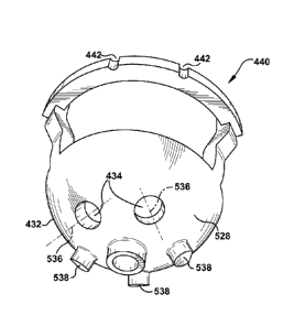
With reference to Figs. 4-5, the guide 426 (hereafter described as being
physical, not virtual) includes a lower guide surface 528 (visible in Fig. 5)
configured to contact an upper implant surface 222 of the stock prosthetic
implant,
here presumed to be an acetabular cup implant 216, when the lower implant
surface 224 is in contact with the acetabulum 110. At least a portion of the
lower
guide surface 528 is contoured to substantially mate with at least a portion
of the
upper implant surface 222, as will be discussed below. The term "mate" is used
herein to indicate a relationship in which the contours of two structures are
at least
partially matched or coordinated in at least two dimensions. For example, both
the
lower guide surface 528 and the upper implant surface 222 could have profiles
that
are concavely curved, convexly curved, planar/linear, or any combination of
those
or other profile shapes. The guide 426 also includes an upper guide surface
430
spaced longitudinally apart from the lower guide surface 528 by a guide body
432.
CA 02815654 2013-04-23
WO 2012/058344
PCT/US2011/057944
-13-
The upper guide surface 430 is accessible to a user when the lower guide
surface 528 is in contact with the upper implant surface 222.
The patient's name, identification number, surgeon's name, and/or any
other desired identifier may be molded into, printed on, attached to, or
otherwise
associated with the guide 426 in a legible manner. The guide 426 may be made
by
any suitable method such as, but not limited to, selective laser sintering
("SLS"),
fused deposition modeling ("FDM"), stereolithography ("SLA"), laminated object
manufacturing ("LOM"), electron beam melting ("EBM"), 3-dimensional
printing ("3DP"), contour milling from a suitable material, computer numeric
control ("CNC"), other rapid prototyping methods, or any other desired
manufacturing process.
At least one guiding aperture 434 extends through the guide body 432
between the upper and lower guide surfaces 430 and 528 at a predetermined
aperture location with respect to the guide body (i.e., a predetermined
placement of
the guiding aperture 434 on the guide body). As shown in Figs. 4-5, the at
least
one guiding aperture 434 defines a predetermined target trajectory 536 through
the
guide body 432. At least one of the target trajectory 536 and the aperture
location
of each guiding aperture 434 can be preselected responsive to preoperative
imaging
of the patient tissue, as previously described. When the guide 426 is placed
atop
the acetabular cup implant 216 as described above (with the lower guide
surface 528 substantially mated with at least a portion of the upper implant
surface 222), at least one of the guiding apertures 434 is collinear with a
corresponding fastener aperture 220 in the acetabular cup implant, as will be
discussed below. The term "collinear" is used herein to indicate that central
axes
of each of two structures lie along the same line. However, the diameters of
the
"collinear" guiding apertures 434 and fastener apertures 220 could differ from
each
other. In short, the aperture locations of the guiding apertures 434 are
preselected
to facilitate placement of a fastener into the stock prosthetic implant (e.g.,
the
acetabular cup implant 216 for the embodiment of Figs. 4-10) and the
underlying
patient tissue at a preselected fastener location and a preselected fastener
trajectory
after removal of the guide 426 from the stock prosthetic implant.
-14-
The lower guide surface 528 shown in Fig. 5 includes at least one locating
protrusion 538.
Each of the locating protrusions 538, when present, extends from the lower
guide surface
528 and is configured to nest into, or mate with, a preselected fastener
aperture 220 of the
acetabular cup implant 216, to assist with mating of the lower guide surface
with at least a
portion of the upper implant surface 222. As can be seen in Fig. 5, the
locating protrusions
538 in the depicted embodiment are simple protrusions and are not configured
to accept a
fastener.
An orienting feature 440, such as the depicted extension in Figs. 4-5, may be
provided to the guide 426. As shown here, for use with the acetabular cup
implant 216, the
orienting feature 440 may extend, perhaps substantially, longitudinally and/or
laterally
from the guide 426, but the direction, amount, and type of extension will
depend upon the
location and type of body tissue with which the guide 426 is being used. The
orienting
feature 440 may be configured to enter a predetermined orienting relationship
with a
landmark (not shown), such as a guide pin, wire, marking, and/or other
location indicator
previously placed in a predetermined relationship with the patient tissue,
such
predetermined orienting relationship occurring when the lower guide surface
528 is in
mating contact with at least a portion of the upper implant surface 222 in a
predetermined
relative guide/implant orientation. (The predetermined relative guide/implant
orientation is
achieved when the guide 426 and acetabular cup implant 216 are mated in a
desired
manner, as predetermined via preoperative imaging and/or analysis.) The
landmark may
be any suitable two- or three-dimensional landmark such as, but not limited
to, a native or
acquired anatomical feature of the patient tissue and/or a separately provided
landmark
placed with the assistance of a guide. The landmark could also or instead be
placed using a
robotic surgical aid, adjustable reusable (e.g., "dial-in") tools,
intraoperative imaging, or
any other suitable placement aid. For example, a portion of the orienting
CAN_DMS \ 1 1 0822937 \ 1
CA 2815654 2018-02-28
CA 02815654 2013-04-23
WO 2012/058344
PCT/US2011/057944
-15-
feature 440 could be configured to mate with a preselected surface of the
patient
tissue acting as a landmark such that the mating of the orienting feature and
the
patient tissue indicates that the predetermined orienting relationship between
the
orienting feature and this patient tissue landmark has been achieved.
Optionally, an original landmark could have been previously placed, then
removed for any reason (e.g., to facilitate machining of the acetabulum 110
surface). A second landmark may then be placed at the same location and with
the
same location as the original landmark, such as via reusing the cavity in the
surface
left by the removal of the original landmark. Indeed, the remaining cavity in
the
surface itself may serve a landmarking function. Through these or any other
such
transformations of physical manifestations, the position information
represented by
the original landmark and preoperatively planned may be preserved and used
during various stages of the surgical procedure regardless of the way in which
that
position landmark is made available to the user at those various stages.
Optionally,
the orienting feature 440 may include an orienting indicator 442. When
present,
the orienting indicator 442 may be configured to achieve a predetermined
signaling
relationship (the signaling relationship being directly related to the
orienting
relationship) with the landmark, as will be described below, while the guide
426
and the stock prosthetic implant -- here, the acetabular cup implant 216--are
in the
predetermined relative guide/implant orientation. For example, in the first
configuration of the first embodiment shown in Figs. 4-5, the orienting
feature 440
is a bridge-type structure extending from the guide body 432 and the orienting
indicators 442 are notches in the orienting feature 440, each shaped to
somewhat
closely surround at least a portion of the diameter of a guide pin or other
three-dimensional landmark to achieve the predetermined signaling
relationship.
The landmark(s) were previously placed in any suitable manner in predetermined
locations at the surgical site. Accordingly, the predetermined signaling
relationship between the landmark(s) and the orienting indicator(s) 442
assists the
user in placing the guide 426 into a predetermined guide orientation with
respect to
the patient tissue.
When the guide 426 and the stock prosthetic implant are held in a
predetermined relative guide/implant orientation (e.g., through the use of
CA 02815654 2013-04-23
WO 2012/058344
PCT/US2011/057944
-16-
locating protrusions 538, frictional engagement, any other mechanical linkage
[e.g., nesting], or even merely coordinated movement of each by the user),
then the
stock prosthetic implant is manipulated in concert with the guide.
Accordingly,
movement of the guide 426 into the predetermined guide orientation--as
signaled
by coordination of the landmark(s) and the orienting feature 440--will
concurrently
move the stock prosthetic implant into a predetermined implant orientation
with
respect to the patient tissue. One of ordinary skill in the art can readily
preoperatively plan the placement and type of landmark(s), as well as the
structure
and type of orienting feature(s) 440 and/or orienting indicator(s) 442 to
assist the
user in guiding the stock prosthetic implant into the predetermined implant
orientation and/or location with respect to the patient tissue for a
particular
application of the present invention.
While the orienting indicator 442 is shown in Figs. 4-5 as being a notch,
any suitable structure, notch-like or otherwise, could be used as an orienting
indicator. For example, the orienting indicator 442 could be a lug extending
from
the orienting feature 440, a visual indicator such as a line drawn or etched
on the
orienting protrusion, or even a mechanical system such as a latch or trip-
wire.
As another example, a second configuration of the first embodiment of the
present invention is shown in Figs. 6-7. Structures of Figs. 6-7 that are the
same as
or similar to those described with reference to Figs. 4-5 have the same
reference
numbers. As with all alternate configurations shown and described herein,
description of common elements and operation similar to those in previously
described configurations will be omitted, for clarity. In the second
configuration,
the guide 426 includes multiple locating protrusions 538 and multiple
orienting features 440. One of the orienting features 440 includes a notchlike
orienting indicator 442a configured to interact with a landmark in an active
(e.g., mechanically interacting) signaling relationship, and the other of the
orienting features 440 includes a more passive orienting indicator 442b, which
is
depicted here as an inscribed line on the orienting feature and is configured
to
provide a more passive (e.g., visually observed) signaling relationship with a
landmark.
-17-
As depicted in Figs. 6-7, the guide 426 may include at least one central guide
aperture
644 extending through the guide body 432 between the upper and lower guide
surfaces 430
and 528. The central guide aperture 644 may be configured to accept a landmark
placed in
a predetermined relationship with the patient tissue. For example, the central
guide
aperture 644 of the second configuration is substantially centrally located in
the guide body
432. If a central landmark (not shown) is placed in a similarly central
location of the
patient tissue at the surgical site and accepted through the central guide
aperture 644, the
guide body 426 could pivot about that central landmark (as if on an axis)
under rotational
force exerted by the user. In such manner, the guide 426 (and, by extension,
the stock
prosthetic implant when held in the predetermined relative guide/implant
relationship) can
initially be placed in a desired position with respect to the patient tissue--
agnostic of
rotational orientation--and then the rotational orientation can be set via
pivoting of the
guide and stock prosthetic implant about the central landmark until the
orienting feature
440 achieves the predetermined orienting relationship with an other landmark,
spaced apart
from the central landmark. Optionally the central landmark could be a
guidewire (not
shown).
As an alternative to this agnostic placement of the guide 426 and
nested/attached
stock prosthetic implant at the surgical site and subsequent rotation into
position, the guide
426 and the stock prosthetic implant could be concurrently placed into contact
with at least
one landmark (which could include the central landmark) at a location spaced
apart from
the patient tissue at the surgical site. For example, a landmark could be an
elongate guide
pin, and a notch-like orienting indicator 442 could be placed into the
signaling relationship
with a protruding end of the guide pin some distance from the patient tissue.
In this
optional situation, the stock prosthetic implant would be guided into the
predetermined
implant orientation concurrently with being brought into contact with the
patient tissue as
CAN_DMS: \110822937\1
CA 2815654 2018-02-28
CA 02815654 2013-04-23
WO 2012/058344
PCT/US2011/057944
-18-
the orienting indicator 442 slides along the length of the guide pin via a
rail-like
dynamic guiding technique.
Figs. 8, 9, and 10 depict third, fourth, and fifth configurations,
respectively,
of the first embodiment of the present invention. In the third configuration
of
Fig. 8, the guide 426 is configured to substantially mate with a fairly large
portion
of the acetabular cup implant 216. Relief slots 846 may extend laterally
inward
from an outer guide rim 848 and, when present, can help provide for a
temporary
reduction in circumference of the guide 426 under lateral force (e.g., a
squeeze by
the user) to elastically deform the guide 426 and facilitate placement of the
guide
into the acetabular cup implant 216. When the lateral force is released, the
guide 426 expands back to the original circumference to nest closely within
the
acetabular cup implant 216.
As shown in Fig. 8, a plurality of two-dimensional orienting features 440
are provided on the upper guide surface 430. The orienting features 440 shown
in
Fig. 8 are visual indications--here, darkened carets--on the outer guide rim
848 and
may help guide the user in placing the guide 426 in a predetermined mating
relationship with the stock prosthetic implant, to assist in carrying out the
preoperative plan including the placement of the fasteners to secure the stock
prosthetic implant in a desired manner. For example, the orienting features
440
shown in Fig. 8 may be placed to correspond to (e.g., line up radially with)
the positions of one or more landmarks previously placed on or near the
acetabulum 110. Optionally, the orienting features 440 may be placed to
correspond to the position(s) of one or more landmarks previously placed on
the
acetabular cup implant 216, to help orient the guide 426 into the
predetermined
relative guide/implant relationship with the stock prosthetic implant. This
orientation between the guide 426 and the acetabular cup implant 216 may be
especially important when the guide and acetabular cup implant are held
relatively
firmly to one another during their insertion to the surgical site.
The guides 426 in Figs. 9 and 10 each are configured to substantially mate
with a much smaller portion of the acetabular cup implant 216 than are the
guides
of Figs. 4-8. The guide 426 of the fourth configuration, shown in Fig. 9, is
shaped
like a segment of a circle and may include one or more laterally oriented
locating
CA 02815654 2013-04-23
WO 2012/058344
PCT/US2011/057944
-19-
protrusions 538 that help steady and/or position the guide at a desired
position on
the acetabular cup implant 216. When present, the locating protrusions 538 may
contact the acetabular cup implant 216 at a predetermined position to indicate
that
the guide 426 is placed correctly on the acetabular cup implant, which could
include a structure (not shown) configured to engage with the locating
protrusions.
The guide 426 of Fig. 9 might be placed asymmetrically upon the acetabular cup
implant 216, with the outer guide rim 848 being aligned with an outer rim of
the
acetabular cup implant.
Similarly to the guide 426 of Fig. 9, the guide 426 of the fifth
configuration, shown in Fig. 10, is substantially shaped as a portion of a
spherical
shell and might be placed in any desired orientation on the acetabular cup
implant 216 which would result in the desired fastener placement. As can be
seen
in Fig. 10, locating protrusions 538 may extend from any surface of the guide
426.
For example, at least one locating protrusion 538 of Fig. 10 extends downward
from the lower guide surface 528, toward the upper implant surface 222 when
the
guide 426 is mated with the acetabular cup implant 216. A locating protrusion
538
extending in this orientation may be configured to nest into a preselected one
of the
fastener apertures 220 to provide positive location and increased stability
between
the guide 426 and the acetabular cup implant 216.
Fig. 11 illustrates, in schematic cross-section, an example of the guide 426
being used to define the predetermined target trajectories 536 and aperture
locations, with fasteners 1150 being temporarily placed through selected ones
of
the guiding apertures 434 in Fig. 11 to show the target trajectories' role in
guiding
fasteners, be they screws, nails, brads, rods, or any other suitable
fasteners. It is
contemplated, though, that in most use environments, the guide 426 will be
removed from the acetabular cup implant 216 before fasteners 1150 are
installed
on the acetabular cup implant.
It is apparent from Fig. 11 that the guide body 432 should be thick enough
that each of the guiding apertures 434 can influence the trajectory of an
elongate
body passing therethrough. If the guide body 432 is too thin, the elongate
body
may precess within the guiding aperture 434 and deviate from the target
trajectory
536. The elongate body intended for insertion through the guiding apertures
434
CA 02815654 2013-04-23
WO 2012/058344
PCT/US2011/057944
-20-
could be a fastener, a surgical tool, a guide pin, or any other suitable
structure, and
could be of any suitable size with respect to a corresponding guiding aperture
434
and/or fastener aperture 220. The elongate body could contact all, a portion
of, or
none of the inner walls of the guiding aperture 434 and/or fastener aperture
220, as
desired.
At least one depth limiting feature 1152 may be provided to the guide 426
to limit further motion of the elongate body along the target trajectory and
into the
patient tissue past a predetermined depth. When the elongate body is a
surgical
tool, for example, the depth limiting feature 1152 may be a blocking stud, as
shown in Fig. 11, which "catches" a drill chuck, a reamer shoulder, or another
structure associated with the surgical tool when the surgical tool has reached
the
predetermined depth. It is contemplated that the depth limiting feature 1152
might
be custom-designed and -manufactured for that particular patient tissue with
the
assistance of preoperative imaging. The depth limiting feature 1152 may also
or
instead be provided by the fastener 1150, such as, but not limited to, a head
of the
fastener having a diameter greater than the shaft and preventing the fastener
head
from passing through the fastener aperture 220--in this example, the depth
limiting
feature is the fastener head and may be adequately provided by a stock
fastener.
Figs. 12-15 show top and cross-sectional side views of a portion of a
surgical procedure in which the guide 426 may assist with providing target
trajectories 536 and locations for fasteners 1150 to secure an acetabular cup
implant 216 to an acetabulum 110. In Figs. 12-13, the distal ends of three
landmarks 1254 (shown here as guide pins) have been placed in the hip bone 100
in or near the acetabulum 110 (optionally with the assistance of a pin guide,
not
shown). The acetabular cup implant 216 has been placed in contact with a
prepared acetabulum 110. Here, the acetabular cup implant 216 includes
orienting
features 440a to help the user rotationally orient the acetabular cup implant
with
the visual assistance of the two landmarks 1254 located outside the
acetabulum 110 on the hip bone 100. The orienting features 440a might not be
used for situations in which the acetabular cup implant 216 is rotationally
symmetrical, but could be provided even with a symmetrical acetabular cup
implant for any other desired reason.
CA 02815654 2013-04-23
WO 2012/058344
PCT/US2011/057944
-21-
Additionally, in Figs. 12-13, a chosen one of the fastener apertures 220 of
the acetabular cup implant 216 has been passed or slid over at least a portion
of a
landmark 1254 (which may be a central landmark, as shown) previously placed in
the acetabulum 110 to help orient the acetabular cup implant within the
acetabulum. Incidentally, this central landmark might have been used to help
prepare the acetabulum 110, such as by guiding a reamer (not shown) to ream
the
acetabulum into a more standardized spherical shape to accept the stock
acetabular
cup implant 216. Optionally, this chosen one of the fastener apertures 220
may differ in size, shape, or any other characteristic from the other
fastener apertures, to indicate and/or facilitate its use with the central
landmark 1254. At the stage shown in Figs. 12-13, the acetabular cup implant
216
is either sitting loosely in the acetabulum 110 or has a tenuous press-fit
relationship
with the acetabulum--in any case, there have been no fasteners 1150 installed,
and
the acetabular cup implant 216 is thus not yet a functional portion of a
prosthetic
hip joint.
Figs. 14-15 show the hip bone 100 and acetabular cup implant 216 of
Figs. 12-13 with the addition of an overlying guide 426 according to the
present
invention. Similar to the orientation of the acetabular cup implant 216, the
guide 426 in Figs. 14-15 has a guiding aperture 434 which been passed or slid
over
at least a portion of the central landmark 1254 previously placed in the
acetabulum 110 to help achieve a predetermined guide orientation within the
acetabular cup implant. The guide 426, as shown, includes inscribed orienting
features 440b (to distinguish from the orienting features 440a of the
acetabular cup
implant 216) which help rotationally orient the acetabular cup implant with
the
assistance of the two landmarks 1254 located outside the acetabulum 110 on the
hip bone 100. The guide 426 of Figs. 14-15 also includes a bridge-like
orienting
feature 440 including orienting indicators 442 which are in the signaling
relationship with two of the landmarks 1254 in the pictured view. Optionally
and
as previously discussed, at least a portion of the bridge-like orienting
feature 440
could include a shaped profile (not shown) which achieves the signaling
relationship through mating with a preselected portion of the patient tissue.
CA 02815654 2013-04-23
WO 2012/058344
PCT/US2011/057944
-22-
The stock acetabular cup implant 216 has a predetermined number of
fastener apertures 220, at least one of which may be extraneous, as previously
discussed. The guide 426 also has a predetermined number of guiding
apertures 434, which may be any number, but is contemplated to be no more than
the predetermined number of fastener apertures 220 in the acetabular cup
implant.
At least one guiding aperture 434 should be collinear or otherwise coincident
in
some physical property with a predetermined one of the fastener apertures 220.
In
this manner, the guide 426 acts as a "mask" to obscure those fastener
apertures 220
which are not predetermined to receive a fastener 548, while providing a
location
and target trajectory 536 for installation of fasteners 1150 into those
fastener
apertures which are to be used in securing the acetabular cup implant 216 to
the hip
bone 100.
As is apparent from the cross-sectional view of Fig. 15, the locating
protrusions 538 on the underside of the guide 426 each nest into preselected
ones
of the fastener apertures 220 to help provide positive locating and
stabilizing
features to the guide 426. Regardless of the presence of locating protrusions
538,
however, it is contemplated that at least a portion of the guide 426 will be
in
contact with the acetabular cup implant 216 in a predetermined orientation
when
the structures have achieved the configuration shown in Figs. 14-15. The
locating protrusion 538 shown in Fig. 15 nests into a central one of the
fastener
apertures 220, which also holds a central landmark 1254. Accordingly, this
locating protrusion 538 doubles as a guiding aperture 434 and can accept a
fastener
or other structure inserted thereinto.
One example sequence of use for any configuration of the first embodiment
of the present invention is shown in Figs. 16-21. In Fig. 16, the acetabular
cup
implant 216 has been placed in the acetabulum 110. It should be understood
that
the acetabular cup implant 216 is not necessarily in the predetermined implant
orientation at this point in the procedure. The guide 426 is then placed atop
the
acetabular cup implant 216 with the lower guide surface 528 in mating contact
(optionally with the assistance of one or more locating protrusions 538) with
the
upper implant surface 222 in the predetermined relative guide/implant
orientation.
CA 02815654 2013-04-23
WO 2012/058344
PCT/US2011/057944
-23-
The guide 426 and the acetabular cup implant 216 are then shifted as
desired, independently or concurrently and optionally with the use of one or
more
orienting features 440 and/or orienting indicators 442, as described above
with
reference to Figs. 4-8, until the acetabular cup implant is in the
predetermined
implant orientation and the guide is in a predetermined guide orientation.
This
view is shown in Fig. 17.
Once the acetabular cup implant 216, guide 426, and acetabulum 110 have
achieved the relative positioning and configuration shown in Fig. 17, the user
can
prepare for installation of the fasteners 1150 in the preselected aperture
locations
(indicated by the placement of the guiding apertures 434 on the guide) and
along
the target trajectories 536. For example, when fastener cavities 1956, pilot
or
otherwise, are to be pre-drilled to receive the fasteners 548, at least one
guiding
aperture 434 may be configured to guide a surgical tool 1858 through a
corresponding fastener aperture 220 and into the patient tissue along the
target
trajectory 536 to create the fastener cavity in the patient tissue, as shown
in
Figs. 18-20. Though omitted here for clarity, a guiding sleeve (not shown) may
be
placed into the guiding aperture 434 (and optionally extend into the
corresponding
fastener aperture 220) to protect the guide 426 and/or the acetabular cup
implant 216 from the forces (e.g., rotational) exerted by the surgical tool
1858.
When present, the guiding sleeve may also serve as an extension of the guiding
aperture 434 to emphasize the target trajectory 536 and help maintain
collinearity
of the fastener cavity 1956 with the target trajectory. As another example,
not
shown, when the fastener 1150 does not require a pre-drilled hole (e.g., the
fastener
is a self-tapping screw or a nail), at least one guiding aperture 434 may be
configured to guide the fastener itself through a corresponding fastener
aperture 220 and into the patient tissue along the target trajectory 536 into
the final
arrangement of Fig. 21.
In the former arrangement (i.e., guide 426 guides surgical tool 1858), the
guide may be removed from the acetabular cup implant 216 once the fastener
cavities 1956 are produced, such as in Fig. 20. The acetabular cup implant 216
is
maintained in place while fasteners 1150 are then installed directly through
the
selected fastener apertures 220 (i.e., those with associated fastener cavities
already
CA 02815654 2013-04-23
WO 2012/058344
PCT/US2011/057944
-24-
drilled) to secure the acetabular cup implant to the acetabulum 110, forming
the
final arrangement shown in Fig. 21. Optionally, the fastener apertures 220 may
be
countersunk (not shown) to accommodate each fastener head 2160 within the
material of the acetabular shell 218 and present a substantially smooth upper
implant surface 222. Alternately or additionally, at least one fastener head
2160
could remain protruding from the acetabular shell 218 above the upper implant
surface 222, as shown in Fig. 21, particularly if such would be desirable in
attaching another prosthetic implant structure (e.g., an acetabular liner, not
shown)
to the acetabular cup implant 216. As other options, the fasteners 1150 could
be
substantially headless or could have fastener heads 2160 which interact with
the
inner surface of the fastener apertures 220 to remain recessed below the upper
implant surface 222 while still providing a securing function to the
acetabular cup
implant 216.
In the latter arrangement (i.e., guide 426 guides fastenerls1 1150), the guide
may be configured to accommodate the fastener heads 2160, if any, before the
guide is removed from the acetabular cup implant 216. For example, the guide
426
could be frangible and thus equipped for at least partial disassembly and
removal when the fasteners 1150 have been substantially guided along the
target
trajectories 536. As another example, the guiding apertures 434 could be
elongate
and configured to create a slot open to the lateral edge of the guide body
432, so
that the guide 426 can be moved laterally out of engagement with the
acetabular
cup implant 216 without changing the trajectories of the partially-inserted
fasteners 1150 from the target trajectories 536. Regardless of the operation
or
structure employed, at least one of the guiding apertures 434, fastener
apertures 220, and fasteners 1150 could be configured to allow removal of the
guide 426 from the acetabular cup implant 216, again without changing the
trajectories of the partially-inserted fasteners from the target trajectories
536.
When the fasteners 1150 are left partially inserted at the time the guide 426
is
removed, the user may complete their insertion without the guiding influence
of
the guide; it will generally be desirable, however, that the guide not be
removed
until there is substantial certainty that the fasteners are adequately engaged
with
the patient tissue of the hip bone 100 and will continue to follow their
target
CA 02815654 2013-04-23
WO 2012/058344
PCT/US2011/057944
-25-
trajectories 536 during the remaining insertion operation even without the
guide
being present.
Regardless of the way in which the guide 426 is removed, the acetabular
cup implant 216 is anticipated to be securely fastened to the acetabulum 110
at, or
shortly after, the guide removal is accomplished. "fhe user may then continue
with
the surgical processes to complete the installation of the prosthetic implant
and to
conclude the surgical procedure as desired.
In summary, the guide 426 can assist the user with placement of
fasteners 1150 into a prosthetic implant and a patient tissue in a desired
fashion by
providing target trajectories 536 and aperture (that is, insertion) locations
for each
fastener. Each target trajectory 536 and each aperture location is preselected
responsive to preoperative imaging of the patient tissue, with each target
trajectory
and each aperture location being preselected to facilitate placement of a
fastener 1150 into a stock prosthetic implant and the underlying patient
tissue at a
preselected fastener location and a preselected fastener trajectory before
and/or
after removal of the guide 426 from the stock prosthetic implant. The guide
426
also may be configured to enter a predetermined orienting relationship, such
as
with the assistance of an orienting feature 440, with a natural or acquired
landmark
(not shown), such as a guide pin, wire, marking, and/or other location
indicator
previously placed in a predetermined relationship with the patient tissue, to
facilitate correct location of at least one target trajectory 536 with respect
to the
patient tissue.
Figs. 22-27 depict a guide 426' according to a second embodiment of the
present invention and related structures. The guide 426' of Figs. 25-27 is
similar
to the guide 426 of Figs. 4-10 and therefore, structures of Figs. 25-27 that
are the
same as or similar to those described with reference to Figs. 4-10 have the
same
reference numbers with the addition of a "prime" mark. Description of common
elements and operation similar to those in the previously described first
embodiment will not be repeated with respect to the second embodiment.
Fig. 22 is a partial perspective view of the scapula, with particular emphasis
on the glenoid fossa 2262. A glenoid implant 2364, shown in Figs. 23-24, is
the
stock prosthetic implant for use with a prosthetic shoulder replacement
surgery for
CA 02815654 2013-04-23
WO 2012/058344
PCT/US2011/057944
-26-
the second embodiment of the present invention. This glenoid implant 2364
happens to be a metaglene implant, which accepts a glenosphere component (not
shown) in a known manner for a reverse shoulder prosthesis. The glenoid
implant 2364 includes a lower implant surface 224', an upper implant surface
222',
and a plurality of fastener apertures 220' extending between the lower and
upper
implant surfaces. Certain configurations of the glenoid implant 2364 may also
include an implant shaft 2466.
During installation of the glenoid implant 2364, a shaft aperture
(not shown) is drilled into the patient tissue (here, the patient's glenoid
fossa 2262)
and the implant shaft 2466 is placed in the shaft aperture for initial
securement and
stabilization before the fasteners 1150' are installed. The implant shaft 2466
may
act as a pivot point for rotation of the glenoid implant 2364 during movement
of
the glenoid implant into the predetermined implant orientation, similar to the
procedure described above for the first embodiment. In this situation, the
shaft
aperture serves as a landmark 1254' to communicate pre-operatively planned
location information to the user during the surgical procedure. The implant
shaft 2466 may also act to help stabilize the glenoid implant 2364 on an
ongoing
basis, after conclusion of the described surgical procedure. 'fhe glenoid
fossa 2262
could be reamed, cut, grafted, or otherwise altered from its native or
pathologic
state to accept the glenoid implant 2364, as desired according to the
preoperative
plan and/or an intraoperative decision.
Optionally, a landmark 1254' such as the previously described guidewire
may be passed through the glenoid implant 2364 and into the patient tissue of
the
glenoid fossa 2262 through the use of a shaft aperture 2368 passing through
the
implant shaft 2466. When the shaft aperture 2368 is used in this manner, the
landmark 1254' may he placed first, to help locate the glenoid implant 2364
upon
the glenoid fossa 2262, or the landmark may be placed into a glenoid implant
already in place on the glenoid fossa, to help with location of the guide 426'
upon
the glenoid implant.
The desire for use of one or more landmark(s) 1254' and/or guide(s) 426'
for the shoulder use environment stems from the relatively open plateau of the
glenoid fossa 2262, on which the glenoid implant 2364 can be positioned and
CA 02815654 2013-04-23
WO 2012/058344
PCT/US2011/057944
oriented a number of different ways. In contrast, the acetabulum 110 tends to
naturally cup and settle an appropriately sized acetabular cup implant 216,
inserted
by a knowledgeable user, into one of a few positions, and the rotational
orientation
of the acetabular cup implant can then be refined through use of the orienting
feature(s) 440, when present. Particularly in a revision situation, due to
anatomic
abnormalities, it may be difficult to position either of these components in
the
glenoid fossa 2262 or acetabulum 110, as the case may be. This difficulty
generally stems from bone loss or surgical alteration of the patient tissue
resulting
in a loss of natural landmarks.
A guide 426' for use with the glenoid implant 2364 is shown in
Figs. 25-27. As can be seen in Fig. 26, the guide 426' includes a central
protrusion 2670 configured to nest into the shaft aperture 2368 of the glenoid
implant 2364. In the second embodiment, the fastener apertures 220' of the
glenoid implant 2364 also serve to accept the locating protrusions 538' of the
guide 426', which surround each of the fastener apertures, as shown. The
fastener
apertures 220' are optionally countersunk to accept the locating protrusions
538'.
When a countersunk fastener aperture 220' is provided for a locating
protrusion 538', whether the countersunk feature is added by the user or
originally provided by the implant manufacturer, the countersunk portion might
also or instead be used to accept a fastener head 2160' to provide a smooth
upper
implant surface 222' with no protruding fastener heads when securement of the
glenoid implant 958 to the patient tissue is complete. With reference to Fig.
26,
the guiding apertures 434' each can be seen to be located on the lower guide
surface 528' in a position coincident with the fastener apertures 220' on the
upper
implant surface 222' when the guide 426' is mated with the glenoid implant
2364
as shown in Fig. 27 (in this Figure, the glenoid implant is located directly
underneath the guide 426', as indicated by the dashed leader line). However,
as
can be seen in Figs. 25 and 27, the location of the fastener apertures 220'
upon the
upper guide surface 430' is dictated by the target trajectory 536' defined by
each
fastener aperture and is patient-specific, being preselected responsive to
preoperative imaging of the patient tissue.
CA 02815654 2013-04-23
WO 2012/058344
PCT/US2011/057944
-28-
An optional handling feature 2572 is indented into the upper guide
surface 430' and is configured as a connection point for a handling tool
(not shown), which may provide assistance with moving the guide 426' within
the
surgical field. Because the handling feature 2572 shown in the figures is
located
collinearly with the implant shaft 2466, the handling tool can be used to
rotate the
guide 426' about an axis defined by the implant shaft--this axis, when
present, is
acting as a landmark 1254' by indicating information to the user regarding a
pre-
planned location of the surgical site. While the handling feature 2572 shown
is a
void adapted to receive a hex-head driver, any suitable handling feature may
protrude from, and/or be recessed into, any surface of the guide 426' and may
have
any desired shape or configuration. Sometimes the available maneuvering space
in
a surgical field is relatively restricted, and it may be useful for a forceps,
hex
wrench (perhaps with a frictional fit or other feature to nest into the
handling
feature 2572), Kocher tool, hemostat, or other user-manipulated handling tool
(not
shown) to selectively interact with the handling feature to hold the guide
426'
steady and/or to move the guide to a desired position. One or more features,
such
as indents, apertures, cavities, lugs, undercuts, or any other suitable
structures
could be provided to the handling feature 2572 or to any other structure of
the
guide 426' to facilitate gripping of the guide by any handling tool, in
general,
and/or by a particular handling tool.
In use, the guide 426' of the second embodiment operates similarly to the
guide 426 of the first embodiment. The glenoid implant 2364 of Figs. 23-24 is
placed upon the glenoid fossa 2262 surface. Optionally, an implant-receiving
aperture (not shown) may have been previously drilled in the glenoid fossa
2262
surface--if so, the implant shaft 2466 is inserted into the implant-receiving
aperture
as a part of placing the lower implant surface 224' in contact with the
patient
tissue. The guide 426' is placed atop the glenoid implant 2364 with the lower
guide surface 528" in contact with the upper implant surface 222'. When
present,
the locating protrusions 538' of the guide 426' may mate with the fastener
apertures 220' of the glenoid implant 2364.
Once the glenoid implant 2364 and guide 426' are mated together in the
predetermined relative guide/implant orientation atop the glenoid fossa 2262
CA 02815654 2013-04-23
WO 2012/058344
PCT/US2011/057944
surface, the glenoid implant and guide can be moved concurrently to move both
the guide and the glenoid implant into predetermined guide and implant
orientations with respect to the glenoid surface. In other words, engagement
between the guide 426' and the glenoid implant 2364 causes forces exerted upon
the guide to be transferred to the glenoid implant, and the user can move both
the
glenoid implant and the guide concurrently by moving just the guide. For
example, and presuming that the glenoid implant 2364 includes an implant
shaft 2466 received into an implant-receiving aperture in the glenoid fossa
2262
surface, a clockwise force (indicated by clockwise arrow 2774 in Fig. 27)
exerted
upon the orienting feature 440' will pivot the guide 426'--and thus the mated
glenoid implant--about the implant shaft.
The guide 426' and mated glenoid implant 2364 may be rotated, for
example, until the orienting indicator 442' achieves a predetetIllined
signaling
relationship with a landmark 1254' such as the depicted guide pin.
Accordingly,
the guide 426' can rotate the glenoid implant 2364 into a predetermined
implant
orientation with respect to the glenoid fossa 2262 surface. As another
example, the
guide 426' and mated glenoid implant 2364 could be placed with the orienting
indicator 442' at, or close to, the predetermined signaling relationship with
the
landmark 1254' before the glenoid implant comes into contact with the glenoid
fossa 2262. In this latter situation, the glenoid implant 2364 could be guided
into
the predetermined implant orientation concurrently with being brought into
contact
with the glenoid fossa 2262 as the orienting indicator 442' slides along the
length
of the guide pin via a rail-like dynamic guiding technique
Once the guide 426' is mated to the glenoid implant 2364 and the orienting
feature 440' has been rotated or otherwise moved into the predetermined
orienting
relationship with the previously placed landmark 1254, the glenoid implant
will
have achieved the predetermined implant orientation. The desired fastener
1150'
locations with respect to the glenoid fossa 2262 surface will correspond to
one or
more of the fastener apertures 220' of the glenoid implant 2364 when the
glenoid
implant has reached the predetermined implant orientation. A surgical tool
1858'
and/or fasteners 1150' can then be guided along the target trajectories 536'
by the
guide 426' through the fastener apertures 220', the guide 426' can be removed
at
-30-
an appropriate stage in the glenoid implant 2364 securement procedure, and
installation of
the glenoid implant and the remainder of the prosthetic shoulder assembly can
then
proceed apace.
Figs. 28-29 depict a guide 426" according to a third embodiment of the present
invention. The guide 426" of Figs. 28-29 is similar to the guide 426 of Figs.
4-10 and
therefore, structures of Figs. 28-29 that are the same as or similar to those
described with
reference to Figs. 4-10 have the same reference numbers with the addition of a
double
"prime" mark. Description of common elements and operation similar to those in
the
previously described first and second embodiments will not be repeated with
respect to the
third embodiment.
In Figs. 28-29, a patient tissue (here, a long bone 2876) having a malunion
problem
has previously been resected, optionally with the assistance of an aid. The
resected tissue
has been removed, and the long bone 2876 has been collapsed along the
resection line
2878. A stock prosthetic implant, shown here as bone plate 2880, has been
placed in a
predetermined implant orientation with respect to the long bone 2876. A guide
426" has
been placed into a predetermined guide/implant orientation with respect to the
bone
plate 2880. The guide 426" includes at least one guiding aperture 434" at a
predetermined aperture location, the guiding aperture(s) 434" each defining a
target
trajectory 536. After achieving the positioning shown in the Figures, the
guide 426" is
used to aid with the attachment of the bone plate 2880 to the long bone 2876
in a manner
analogous to those described above with reference to the first and second
embodiments of
the present invention.
The above description presumes that the guide 426 is removed from the
prosthetic
implant component before completion of the surgery. It is contemplated,
nevertheless, that
the guide 426 and/or a stock prosthetic implant component could be configured
for
maintenance of the guide within the body, perhaps as a part of the completely
installed
prosthetic implant structure. One way in which this might be accomplished,
using as an
example the aforementioned acetabular cup implant 216, is for the fastener
apertures 220
to be located in an area of the acetabular shell 218 which has a recessed
upper implant
CA 2815654 2018-02-28
-31 -
surface 222 to accept the guide 426 in a manner which results in a
substantially even-
profiled composite inner shell surface for smooth contact with the femoral
implant
component, this composite inner shell surface being comprised of the upper
implant
surface in combination with the upper guide surface 430.
It is contemplated that the guide 426 could be used with an instrument or
related
components.
While aspects of the present invention have been particularly shown and
described
with reference to the preferred embodiment above, it will be understood by
those of
ordinary skill in the art that various additional embodiments may be
contemplated without
departing from the spirit and scope of the present invention. For example, the
specific
methods described above for using the guide 426 are merely illustrative; one
of ordinary
skill in the art could readily determine any number of tools, sequences of
steps, or other
means/options for placing the above-described apparatus, or components
thereof, into
positions substantially similar to those shown and described herein. Any of
the described
structures and components could be integrally formed as a single piece or made
up of
separate sub-components, with either of these formations involving any
suitable stock or
bespoke components and/or any suitable material or combinations of materials;
however,
the chosen material(s) should be biocompatible for most applications of the
present
invention. The mating relationships formed between the described structures
need not
keep the entirety of each of the "mating" surfaces in direct
CA 2815654 2018-02-28
CA 02815654 2013-04-23
WO 2012/058344
PCT/US2011/057944
-32-
contact with each other but could include spacers or holdaways for partial
direct
contact, a liner or other intermediate member for indirect contact, or could
even be
approximated with intervening space remaining therebetween and no contact.
Though certain components described herein are shown as having specific
geometric shapes, all structures of the present invention may have any
suitable
shapes, sizes, configurations, relative relationships, cross-sectional areas,
or any
other physical characteristics as desirable for a particular application of
the present
invention. An adhesive (such as, but not limited to, bone cement) could be
used in
conjunction with the system and method described herein. The guide 426 may
include a plurality of structures cooperatively forming the base body and
temporarily or permanently attached together in such a manner as to permit
relative
motion (e.g., pivoting, sliding, or any other motion) therebetween. Any
structures
or features described with reference to one embodiment or configuration of the
present invention could be provided, singly or in combination with other
structures
or features, to any other embodiment or configuration, as it would be
impractical to
describe each of the embodiments and configurations discussed herein as having
all of the options discussed with respect to all of the other embodiments and
configurations. A sleeve (not shown) could be provided to surround
the fastener 1150 and/or surgical tool 1858 during insertion into at least one
of the guiding aperture 434 and the fastener aperture 220--the sleeve
(when present) could extend at least partially into the guiding aperture
and/or the
fastener aperture, and the sleeve could have variable wall thickness about a
circumference thereof in order to place the elongate body in an offset
relationship
with a centerline of the relevant aperture(s). An adhesive (such as, but not
limited
to, bone cement) could be used in conjunction with the system and method
described herein. Any of the components described herein could have a surface
treatment (e.g., texturization, notching, etc.), material choice, and/or other
characteristic chosen to provide the component with a desired interaction
property
(e.g., tissue ingrowth, eluting of a therapeutic material, etc.) with the
surrounding
tissue. A device or method incorporating any of these features should be
understood to fall under the scope of the present invention as determined
based
upon the claims below and any equivalents thereof.
CA 02815654 2013-04-23
WO 2012/058344
PCT/US2011/057944
-33-
Other aspects, objects, and advantages of the present invention can be
obtained from a study of the drawings, the disclosure, and the appended
claims.