Note: Descriptions are shown in the official language in which they were submitted.
CA 02816320 2016-01-28
. ,
Low Lead Ingot
BACKGROUND OF THE INVENTION
100021 Current plumbing materials are typically made from lead containing
copper alloys. One
standard brass alloy formulation is referred to in the art as C84400 or the
"81,3,7.9" alloy
(consisting of 81% copper, 3% tin, 7% lead, and 9% zinc) (herein in after the
"81 alloy"). While
there has been a need, due to health and environmental issues (as dictated, in
part, by the U.S.
Environmental Protection Agency on maximum lead content in copper alloys for
drinking water
applications) and also for cost reasons, to reduce lead contained in plumbing
fitting, the presence
of lead has continued to be necessary to achieve the desired properties of the
alloy. For example.
the presence of lead in a brass alloy provides for desirable mechanical
characteristics and to
assist in machining and finishing the casting. Simple removal of lead or
reduction below certain
levels substantially degrades the machinability as well as the structural
integrity of the casting
and is not practicable.
100031 Removal or rcduction of lead from brass alloys has been attempted
previously. Such
previous attempts in the art of substituting other elements in place of lead
has resulted in major
machining and finishing issues in the manufacturing process, which includes
primary casting,
primary machining, secondary machining, polishing, plating, and mechanical
assembly.
100041 Several low or no lead formulations have previously been described.
See, for example,
products sold under the trade names SeBiLOY* or EnviroBrasse:, Federalle, and
EcoBrase as
well as U.S. patents 7,056,396 and 6,413,330. Figure 1 is a table that
includes the formulation
of several known alloys based upon their registration with the Copper
Development Association.
-1-
CA 02816320 2016-08-02
The existing art for low lead or no lead copper based castings consists of two
major categories:
silicon based materials and bismuth/selenium materials.
100051 However, there is a need for a low-lead casting solution providing a
low-cost alloy with
similar properties to current copper/lead alloys without degradation of
mechanical properties or
chemical properties, as well as significant disruption to the manufacturing
process because of
lead substitution in the material causing cutting tool and finishing problems.
SUMMARY OF THE INVENTION
f00061 One embodiment of the invention relates to a semi-red brass having a
composition of
about 83% to about 91% copper, about 0.1% to about 0.8% sulfur, about 2.0% to
about 4.0% tin,
less than about 0.09% lead, about 4.0% to about 14.0% zinc, and about 1.0% to
about 2.0%
nickel.
100071 One embodiment of the invention relates to a tin bronze having a
composition of about
Rh% in about R9% copper, about 0.1% to about 0.8% sulfur, about 7.5% to about
8.3% tin, less
than 0.09%, lead, about 1.0% to about 5.0%, zinc, and about 1.0% nickel.
(0008jAdditional features, advantages, and embodiments of the present
disclosure may be set
forth from consideration of the following detailed description, drawings, and
claims. Moreover,
it is to be understood that both the foregoing summary of the present
disclosure and the
following detailed description are exemplary and intended to provide further
explanation without
further limiting the scope of the present disclosure claimed.
-2-
=
CA 02816320 2016-08-02
[0008A] In a broad aspect, the invention provides a cast alloy composition
consisting essentially
of a copper content from 83 wt% to 91 wt%, a sulfur content from 0.1 wt% to
0.8 wt%, a tin
content from 2.0 wt% to 4.0 wt%, a lead content of less than 0.09 wt%, a zinc
content from 4.0
wt% to 14.0 wt%, and a nickel content from 1.0 wt% to 2.0 wt%. The alloy also
comprises an
iron content of less than 0.1 wt%, an antimony content of less than 0.02 wt%,
a phosphorous
content from greater than 0 wt% and less than 0.05 wt%, an aluminum content of
0.005 wt%,
a manganese content from 0.01 wt% to 0.7 wt%, a carbon content of from greater
than 0 wt%
to 0.5 wt%, and a titanium content of from greater than 0 wt% to 0.5 wt%.
10008B1 In another aspect, the invention further provides a cast alloy
composition consisting
essentially of a copper content of from 83 wt% to 89 wt %, a sulfur content of
from 0.1 wt%
to 0.8 wt%, a tin content of from 2.0 wt% to 4.0 wt%, a lead content of less
than 0.09 wt%,
a zinc content of from 4.0 wt% to 14.0 wt%, an iron content of less than 0.01
wt%, an antimony
content of less than 0.02 wt%, a nickel content of from 1.0 wt% to 2.0 wt%, a
phosphorus
content of less than 0.05 wt%, an aluminum content less than 0.005 wt%, a
silicon content less
than 0.005 wt%, and a manganese content of 0.02 wt%.
BRIEF DESCRIPTION OF THE DRAWINGS
[0009] The foregoing and other aspects, features, and advantages of the
disclosure will become
more apparent and better understood by referring to the following description
taken in
conjunction with the accompanying drawings, in which:
[00101 Figure 1 provides Table 1 listing formulations for several known
commercial copper
alloys.
-2a-
PCT/US2011/058448 IPEA/KR (27-08-2012)
AUG. 27. 2012 3:13PM FOLEY & LARDNER NO. 7886
P. 19/78
Attny Docket No 055665-5144Pa
100111 Figure 2 provides Table 2 listing formulations for Alloy Groups in
accordance with
embodiments of the present invention.
(00121 Figure 3A provides Table 3 listing alloy formulations for Group 1-A
mechanical property
examples by their respective casting heat. Figure 3B provides Table 4 listing
the results of the
average mechanical property testing of Group I-A by their respective casting
heat.
(0013) Figure 4A provides Table 5 listing alloy formulations for Group
mechanical property
examples by their respective casting heat. Figure 4B provides Table 6 listing
the results of the
average mechanical property testing of Group 1-B.
100141 Figure 5A provides Table 7 listing alloy formulations for Group II-A
mechanical
property examples by their respective casting heat. Figure 5B provides Table 8
listing the results
of the average mechanical property testing of Group II-A.
100151 Figure 6 provides Table 9 listing the typical and minimum properties
observed for
embodiments of certain Alloy Groups of the present invention and those
properties reported for
commercially available alloys such as those in Table 1 (Figure 1).
[0016] Figure 7 provides Table 10 listing the alloy compositions utilized for
the SEM/EDS
testing.
100171 Figures 8A and 8B illustrate element mapping of (0.16% S) sulfur in
Alloy 1-A-1 0a.
[00181 Figure 9A is an SEM of Alloy I-A-10a; Figures 9B-H illustrate element
mapping; Figure
98 is an EDS for Sn; Figure 9C is an EDS for Zn; Figure 9D is an EDS for Cu;
Figure 9E is an
EDS for Fe; Figure 9F is an EDS for Ni; Figure 9G is an EDS for P; Figure 9H
is an EDS for S.
(0019) Figure 10A is a micrograph of Alloy I-A-10a, with regions 1, 2, and 3
marked; Figures
10B-D show the presence of Cu2S, ZnS and Cu-Zn intermetallic phases: Figure
1013 is an EDS
spectra from region 1; Figure 10C is an EDS spectra from region 2; Figure 10D
is an EDS
spectra from region 3.
(00201 Figures 11A-B are optical images of Alloy I-A-10a at low (Figure 11A)
and high
magnifications (Figure 11B).
-3-
4822-0303-2392
s
=
s=
AMENOECt SWITRT.34)
CA 02816320 2013-04-26
PCT/US2011/058448 IPEA/KR (27-08-2012)
AUG. 27.2012 3:14PM FOLEY & LARDNER NO. 7886
P. 20/78
Attny Docket No 055665-5144PCT
[0021] Figure 12A is a SEM of alloy I-B-10a and 12B illustrate element mapping
of sulfur in
Alloy I-8-10a (0.31% S).
[0022) Figure 13A is an SEM of Alloy I-B-10a; Figures 13B-H illustrate element
mapping at
1000x magnification; Figure 1313 is an EDS for Sn; Figure 13C is an EDS for
Zn; Figure 13D is
an EDS for Cu; Figure 13E is an EDS for Fe; Figure 13F is an EDS for Ni;
Figure 13G is an
EDS for P; Figure 13H is an EDS for S.
[0023) Figure 14A is an SEM of Alloy I-B-10b (0.13% 5); Figures 14B-H
illustrate element
mapping at 5000x magnification; Figure 148 is an EDS for Si; Figure 14C is an
EDS for S;
Figure 14D is an EDS for Fe; Figure 14E is an EDS for Cu; Figure 14F is an EDS
for Zn; Figure
140 is an EDS for Sn; Figure 14H is an EDS for Pb; Figure 141 is an EDS for
Ni.
[0024] Figures 15A-B are optical images of Alloy I-B-10a (0.31% S) at low
(Figure 15A) and
high magnifications (Figure 15B).
100251 Figures 16A and 168 illustrate element mapping of sulfur in Alloy II-A-
1 0a (0.30% S).
[0026) Figure 17A is an SEM of Alloy Figures 17B-H illustrate element
mapping;
Figure 17B is an EDS for Sn; Figure 17C is an EDS for Zn; Figure 17D is an EDS
for Cu; Figure
17E is an EDS for Fe; Figure 17F is an EDS for Ni; Figure 17G is an EDS for P;
Figure 17H is
an EDS for S.
[0027) Figure 18A is an SEM of Alloy II-A-10b (0.19% S); Figures 18B-I
illustrate element
mapping at 1000x magnification; Figure 1813 is an EDS for Si; Figure 18C is an
EDS for S;
Figure 18D is an EDS for Fe; Figure 18E is an EDS for Cu; Figure 18F is an EDS
for Zn; Figure
180 is an EDS for Sn; Figure 1811 is an EDS for Pb; Figure 181 is an EDS for
Ni.
[0028] Figures 19A-B are optical images of Alloy 11-A at low (Figure 19B) and
high
magnifications (Figure 19A).
[0029] Figures 20A and 208 illustrate element mapping of sulfur in Alloy III-A
(0.011% S).
[0030) Figure 21A is an SEM of Alloy III-A; Figures 218-H illustrate element
mapping; Figure
21B is an EDS for So; Figure 21C is an EDS for Zn; Figure 21D is an EDS for
Cu; Figure 21E is
-4-
4822-6303-2592
4
.1,
CA 02816320 2013-04-26 )111111ENOIED SHP" I
TiART.34)
CA 02816320 2013-04-26
PCMS2011/058448 IPEA/KR (27-08-2012)
RUU.L /. LOU 3: 14I'M FULLY & LANDNEN NO. 7886
P. 21/78
Attny Docket No 055665-5144PCT
an EDS for Pe; Figure 21F is an EDS for Ni; Figure 21G is an EDS for P; Figure
21H is an EDS
for S.
[00311 Figures 22A-B are optical images of Alloy III-A at low (Figure 22A) and
high
magnifications (Figure 22B).
[00321 Figure 23 is a sulfur free-energy diagram of primary sulfides formed in
Group I-A, I-B &
11-A alloys.
[0033] Figure 24 is a vertical section of different alloys in the Cu-Sn-Zn-S
alloys
[0034] Figure 25A is a phase distribution diagram of alloy I-A-11 a using
Sch.eil cooling, Figure
258 is a magnified part of the phase distribution diagram showing the relative
amounts of
secondary phases.
[0035] Figure 26A is a phase distribution diagram of alloy I-A-11b using
Schell cooling, Figure
26B is a magnified part of the phase distribution diagram showing the relative
amounts of
secondary phases.
[0036] Figure 27A is a phase distribution diagram of alloy I-A-11c using
Schell cooling, Figure
27B is a magnified part of the phase distribution diagram showing the relative
amounts of
secondary phases.
[0037] Figure 28A is a phase distribution diagram of alloy I-A-I I d using
Schell cooling, Figure
28B is a magnified part of the phase distribution diagram showing the relative
amounts of
secondary phases.
[0038] Figure 29A is a phase distribution diagram of alloy I-A-I le using
Schell cooling, Figure
29/3 is a magnified part of the phase distribution diagram showing the
relative amounts of
secondary phases.
[0039] Figure 30A is a phase distribution diagram of C83470 commercial alloy
(Table 1, Figure
1) using Scheil cooling, Figure 30B is a magnified part of the phase
distribution diagram
showing the relative amounts of secondary phases.
[0040] Figure 31 is phase diagram of Vertical Section of Group 1-A.
-5-
4822-6303-2592
SiiEFT(ART.3411
=
N
PCT/US2011/058448 IPEA/KR (27-08-2012)
AUG. 27. 2012 3:15PM FOLEY & LARDNER NO. 7886
P. 22//8
Attny pocket No 055665-5144PC1
10041] Figure 52A is a Schell Phase assemblage diagram of Group 1-A, Figure
32B is a
magnified Scheil Phase assemblage diagram of Group 1-A.
100421 Figure 33 is a vertical Section of Group I-B.
[0043] Figure 34A is a Scheil Phase assemblage diagram of Group I-B Fig, 34B
is a magnified
Scheil Phase assemblage diagram of Group I-B.
[0044] Figure 35 is a vertical Section of Group II-A.
[0045] Figure 36A is a Scheil Phase assemblage diagram of Group II-A, Figure
36B is a
magnified Schell Phase assemblage diagram of Group II-A.
[0046] Figure 37 is a graph of ultimate tensile strength CUTS) showing various
heats of Alloy
Group 1-A compared to several known alloys, indicated by their CDA number.
[0047] Figure 38 is a graph of yield strength showing various heats of Alloy
Group 1-A
compared to several known alloys, indicated by their CDA number.
[0048] Figure 39 is a graph of elongation showing various heats of Alloy Group
1-A compared to
several known alloys, indicated by their CDA number.
[0049] Figure 40 is a graph of ultimate tensile strength (UTS) showing various
heats of Alloy
Group 1-B compared to several known alloys, indicated by their CDA number.
[0050] Figure 41 is a graph of yield strength showing various heats of Alloy
Group 1-B
compared to several known alloys, indicated by their CDA number.
[0051] Figure 42 is a graph of elongation showing various heats of Alloy Group
1-B compared to
several known alloys, indicated by their CDA number.
[0052] Figure 43 is a graph of ultimate tensile strength (UTS) showing various
heats of Alloy
Group II-A compared to several known alloys, indicated by their CDA number.
(0053) Figure 44 is a graph of yield strength showing various heats of Alloy
Group II-A
compared to several known alloys, indicated by their CDA number.
-6-
4822-6303-2592
CA 02816320 2013-04-26
[AMENDED SHEET(ART 34)
CA 02816320 2016-01-28
100541 Figure 45 is a graph of elongation showing various heats of Alloy Group
II-A compared
to several blown alloys, indicated by their CDA number.
100551 Figure 46A illustrates the sulfide particle sizes for a commercial
sulfur brass, Bi Waken.'
(C83470) and Figure 46B is photomicrograph showing particle size of Group I-A
alloy (.13 S ¨
4.45 Zn ¨3.63 Sn).
100561 The patent or application file contains at least one drawing executed
in color. Copies of
this patent or patent application publication with color drawing(s) will be
provided by the Office
upon request and payment of necessary fee.
DETAILED DESCRIPTION OF THE PREFERRED EMBODIMENTS
(0057) In the following detailed description, reference is made to the
accompanying drawings,
which form a part hereof. In the drawings, similar symbols typically identify
similar
components, unless context dictates otherwise. The illustrative embodiments
described in the
detailed description, drawings, and claims are not meant to be limiting. Other
embodiments may
be utilized, and other changes may be made, without departing from the scope
of the
subject matter presented here. It will be readily understood that the aspects
of the present
disclosure, as generally described herein, and illustrated in the figures, can
be arranged.
substituted, combined, and designed in a wide variety of different
configurations, all of which
are explicitly contemplated and made part of this disclosure.
100581 In one embodiment, the invention relates to a composition of matter and
methods for
making same. The composition of matter is a copper-based alloy having a "low"
level of lead as
would be understood by one of ordinary skill in the art of cavity devices that
make contact with
potable water, including, for example, plumbing fixtures. The level of lead is
below that which
are normally used to impart the beneficial properties to the alloy necessary
for usefulness in most
applications, such as tensile strength, elongation, machinability, and
pressure tightness. Prior art
no-lead alternatives to leaded brass typically require changes to the metal
feeding for sand
castings in order to produce sufficient pressure tightness (such as having no
material porosity).
The alloys of the present invention include particular amounts of sulfur, and
in certain
-7-
PCT/US2011/058448 IPEA/KR (27-08-2012)
AUG. 27. 2012 3:16PM FOLEY & LARDNER NO. 7886
P. 24/78
Attny UocKet No 055685-5144PCT
embodiments, the sulfur is added through a preferred method, to impart the
beneficial properties
lost by the reduction in lead.
100591 The alloys of the present invention relate generally to formulations of
suitable semi-red
brass, tin-bronze, and yellow brass, Certain embodiments are formulated for
use primarily in
sand cast applications, permanent mold cast applications, or wrought
applications.
100601 Table 2 (Figure 2) illustrates a group of alloys in accordance with the
present invention.
Each of the alloys is characterized, at least in pat, by the relative low
level of lead (about 0.09%
or less) and the presence of sulfur (about 0.1% to 0.8%).Three groups of semi-
red brass, labeled
Alloy Group I-A, Alloy Group I-B, and Alloy Group IC are provided. In one
embodiment,
these semi-red brass alloys are suitable for sand casting. Three groups of tin
bronze, labeled
Alloy Group II-A, Alloy Group 11-B, and Alloy Group II-C are provided. In one
embodiment,
these tin bronze alloys are suitable for sand casting. Six groups of yellow
brass, labeled Alloy
Group Alloy Group III-B, Alloy Group Alloy Group N-A, Alloy Grow N-
B, and
Alloy Group N-C are provided. In one embodiment the Alloy Group III alloys are
suitable for
permanent mold casting. In one embodiment, the Alloy Group IV alloys are
suitable for wrought
applications.
Alloy components
[00611 The alloys of the present invention comprise copper, zinc, tin, sulfur,
nickel, and
phosphorus. In certain embodiments, one or more of manganese, zirconium,
boron, titanium
and/or carbon are included. Embodiments, other than Group IV wrought yellow
brass, also
include one or more of antimony, tin, nickel, phosphorus, aluminum, and
silicon.
(0062] The alloys, comprise as a principal component, copper. Copper provides
basic properties
to the alloy, including antimicrobial properties and corrosion resistance.
Pure copper has a
relatively low yield strength, and tensile strength, and is not very hard
relative to its common
alloy classes of bronze and brass. Therefore, it is desirable to improve the
properties of copper
for use in many applications through alloying. The copper will typically be
added as a base
ingot. The base ingot's composition purity will vary depending on the source
mine and post-
-8-
4822-6303-2592
CA 02816320 2013-04-26 IMIENDEO, SHEET(AR T.34 )t
PCT/US2011 /058448 IPENKR (27-08-2012)
AUG.27.2012 3:16PM FOLEY & LARDNER NO. 7886
P. 25/78
Attny Docket No 055665-5144PCT
mining processing. Therefore, it should be appreciated that ingot chemistry
can vary, so, in one
embodiment, the chemistry of the base ingot is taken into account For example,
the amount of
zinc in the base ingot is taken into account when determining how much
additional zinc to add to
arrive at the desired final composition for the alloy. The base ingot should
be selected to provide
the required copper for the alloy while considering the secondary elements in
the base ingot and
their intended presence in the final alloy since small amounts of various
impurities, such as iron,
are common and have no material effect on the desired properties.
100631 Lead has typically been included as a component in copper alloys,
particularly for
applications such as plumbing where machinability is an important factor. Lead
has a low
melting point relative to many other elements common to copper alloys. As
such, lead, in a
copper alloy, tends to migrate to the interdendritic or grain boundary areas
as the melt cools.
The presence of lead at interdendritic or grain boundary areas can greatly
improve niachi ability
and pressure tightness. However, in recent decades the serious detrimental
impacts of lead have
made use of lead in many applications of copper alloys undesirable. In
particular, the presence
of the lead at the interdendritic or grain boundary areas, the feature that is
generally accepted to
improve machinability, is, in part, responsible for the unwanted ease with
which lead can leach
from a copper alloy.
[00641 Sulfur is added to the alloys of the present invention to overcome
certain disadvantages
of using leaded copper alloys. Sulfur present in the melt will typically react
with transition
metals also present in the melt to form transition metal sulfides. For
example, copper sulfide and
zinc sulfide may be formed, or, for embodiments where manganese is present it
can form
manganese sulfide. Figure 23 illustrates a free-energy diagram for several
transition metal
sulfides that may form in embodiments of the present invention. The melting
point for copper
sulfide is 1130 Celsius, 1185 Celsius for zinc sulfide, 1610 Celsius for
manganese sulfide, and
832 Celsius for tin sulfide. Thus, without limiting the scope of the
invention, in light of the free
energy of formation, it is believed that a significant amount of the sulfide
formation will be zinc
sulfide for those embodiments having no manganese. It is believed that
sulfides that solidify
-9-
4822-6303-2592
AMENDED SHEET(AR T.34)]
CA 02816320 2013-04-26
PCT/US2011/058448 IPEA/KR (27-08-2012)
AUG. 27. 2012 3:17PM FOLEY & LARDNER NO. 7886
P. 26/78
Attny Docket No 055665-5144PCT
after the copper has become to solidify, thus forming dendrites in the melt,
aggregate at the
interdendtic areas or grain boundaries.
10065] Sulfur provides similar properties as lead would impart to a copper
alloy, without the
health concerns associated with lead. Sulfur forms sulfides which it is
believed tend to aggregate
at the interdendritic or grain boundary areas. The presence of the sulfides
provides a break in the
metallic structure and a point for the formation of a chip in the grain
botmdary region and
improve machining lubricity, allowing for improved overall machinabffity. The
sulfides
predominate in the alloys of the present invention provide lubricity. Good
distribution of
sulphides improves pressure tightness, as well as, machinability.
10066] It is believed that the presence of tin in some embodiments increases
the strength and
hardness but reduces ductility by solid solution strengthening and by forming
Cu-Sn
intermetallic phase such as Cu3Sn. It also increases the solidification range.
Casting fluidity
increases with tin content Tin also increases corrosion resistance. However,
currently Sn is very
expensive relative to other components.
10067] With respect to zinc, it is believed that the presence of Zn is simiLsr
to that of Six, but to a
lesser degree, in certain embodiments approximately 2% Zn is roughly
equivalent to 1 % Sn with
respect to the above mentioned improvements to characteristics noted above. Zn
increases
strength and hardness by solid solution hardening_ However, Cu-Zn alloys have
a short freezing
range. Zn is much less expensive than Sn.
10068] With respect to certain embodiments, iron can be considered an impurity
picked up from
stirring rods, skimmers, etc during melting and pouring operations, or as an
impurity in the base
ingot Such categories of impurity have no material effect on alloy properties.
100691 For red brass and tin bronzes, antimony may be considered an impurity
in the described
alloys. Typically, antimony is picked up from inferior brands of tin, scrap
and poor quality of
ingots and scrap. However, antimony is deliberately added to yellow brasses in
a permanent
mold to increase the dezincification resistance.
-1O-
4822-8303-2592
!AMENDED SHEET(ART 34)1
CA 02816320 2013-04-26
PCT/US2011 /058448 1PEA/KR (27-08-2012)
AU(. 2/. 2012 3 1 8 PM FOLEY & LARDNER O. 7886
P. 27/78
Attny Docket No 055665-5144PC1
(00701 In some embodiments, nickel is included to increase strength and
hardness. Further,
nickel aids in distribution of the sulfide particles in the alloy. In one
embodiment, adding nickel
helps the sulfide precipitate during the cooling process of the casting. The
precipitation of the
sulfide is desirable as the suspended sulfides act as a substitute to the lead
for chip bruiting and
machining lubricity during the post casting machining operations. With the
lower lead content, it
is believed that the sulfide precipitate will minimize the effects of Lowered
machiztability.
[0071) Phosphorus may be added to provide deoxidation. The addition of
phosphorus reduces
the gas content in the liquid alloy, Removal of gas generally provides higher
quality castings by
reducing gas content in the melt and reducing porosity in the finished alloy.
However, excess
phosphorus can contribute to metal-mold reaction giving rise to low mechanical
properties and
porous castings.
[0072) Aluminum is, in some embodiments, such as semi-red brasses and tin
bronzes, treated as
an impurity. In such embodiments, aluminum has harmful effects on pressure
tightness and
mechanical properties. However, aluminum in yellow brass castings can
selectively improve
casting fluidity. It is believed that aluminum encourages a fine feathery
dendritic structure in
such embodiments.
[00731 Silicon is also considered an impurity. In foundries with multiple
alloys, silicon based
materials can lead to silicon contamination in non silicon contaking alloys. A
small amount of
residual silicon can contaminate semi red brass alloys, making production of
multiple alloys near
impossible. In addition, the presence of silicon can reduce the mechanical
properties of semi-red
brass alloys.
[00741 Manganese may be added in certain embodiments. The manganese is
believed to aid in
the distribution of sulfides. In particular, the presence of manganese is
believed to aid in the
formation of and retention of zinc sulfide in the melt. In one embodiment, a
small amount of
ingnganese is added to improve pressure tightness. In one embodiment,
manganese is added as
MnS.
[0075) Either zirconium or boron may be added individually (not in
combination) to produce a
fine grained structure which improves surface finish of castings during
polishing.
-11-
4822-8303-2592
'AMENDED SHEEVART.34)]
CA 02816320 2013-04-26
PCT/US2011/058448 IPEA/KR (27-08-2012)
CA 02816320 2013-04-26
AUG. 27. 2012 3:18PM FOLEY & LARDER NO. 7886
P. 28/78
rµtuiy iJOGICUt rio 05560*-b1441-1.:T
[0076] Carbon may be added in certain embodiments to improve pressure
tightness, reduce
porosity, and improve machinability.
100171 Titanium may be added in combination with carbon, such as in graphite
form. Without
limiting the scope of the invention, it is believed that the titanium aides in
bonding the carbon
particles with the copper matrix, particularly for raw graphite. For
embodiments utilizing copper
coated with carbon, titanium may not be useful to distribute the carbon.
Alloy Characteristics
[0078] In one embodiment, an alloy of the present invention solidifies in a
manner such that a
multitude of discrete particles of sulfur/sulfide are distributed throughout
in a generally tmiform
manner throughout the casting. These nonmetallic sulfur particles serve to
improve lubricity and
break chips developed during the machining of parts cast in this new alloy,
thereby improving
machinability with a significant or complete reduction in the amount of lead.
Without limiting
the scope of the invention, the sulfides are believed to improved lubricity.
[0079] The preferred embodiments of the described alloy retain machinability
advantages of
the current alloys such as the "81" alloy or a similar leaded alloy. Further,
it is believe that due
to the relative scarcity of certain materials involved, the preferred
embodiments of the ingot alloy
will cost considerately less than that of the bismuth and/or selenium alloyed
brasses that are
currently advocated for replacement of leaded brass alloys such as "81". The
sulfur is present in
certain embodiments described herein as a sulfide which is soluble in the
melt, but is precipitated
as a sulfide during solidification and subsequent cooling of the alloy in a
piece part. This
precipitated sulfur enables improved machinability by serving as a chip
breaker similar to the
function of lead in alloys such as the "81" and in bismuth and selenium
alloys. In the case of
bismuth and/or selenium alloys the formation of bismuthides or selenides,
along with some
metallic bismuth, accomplishes a similar objective as this new sulfur
containing alloy. The
improvement in machinability may show up as increased tool life, improved
machining surfaces,
reduced tool forces, etc. This new idea also supplies the industry with a low
lead brass/bronze
-12-
4822-8303-2592
AMENDED SHEENRT 34)
PCT/US2011 /058448 IPEA/KR (27-08-2012)
AUG. 27. 2012 3:19PM FOLEY & LARDNER NO. 7886
P. 29/78
Attny Docket No 055665-5144PCT
which in today's environment is seeing any number of regulatory authorities
limit by law the
amount of lead that can be contained in plumbing fittings.
[0080] Further, alloys to which lead has been added result in an increase in
the temperature
range over which solidification occurs, normally making it more difficult to
produce a leak tight
casting, critical in plumbing fittings. However, lead segregates to the last
regions to solidify and
thereby seals the interdendritic and grain boundary shrinkage which occurs.
This sealing of
interdendritic or grain boundary porosity is not accomplished in the
sulfur/sulfide containing
alloys. Neither is it accomplished in the bismuth and/or selenium alloys.
While bismuth is
similar to lead in the periodic table of the elements, and expands during
solidification, the
amount of bismuth used is small compared to the amount of lead in conventional
alloys such as
the "81". Bi is typically present in commercial alloys in the elemental form.
[0081] One of ordinary skill will appreciate the additional benefits beyond
the performance
properties of the present alloys. Compared to bismuth and selenium the alloys
of.the present
Invention utilize abundantly found elements, whereas both bismuth and selenium
are in relatively
limited supply; and the conversion of brass castings to these materials will
significantly increase
the demand for these limited supply materials. In addition, bismuth has some
health concerns
associated with its use in plumbing fixtures, in part due to its proximity to
lead as a heavy metal
on the periodic table. Further, in certain embodiments, the alloys of the
present invention utilizes
a lower percent of copper than prior art bismuth and selenium compositions.
Yield Benefits
100821 It has been observed that the use of sulfur as a substitute for lead
rather than silicon -
provides superior "yield per melt". With sulfur, the yield per melt ranges
from 70 to 80% as
compared to silicon which can yield 40 to 60% per melt. Normal leaded brass
alloys yield 70 to
80% depending upon process efficiency. As can be appreciated by one of
ordinary skill, such an
increase in yield reflects a substantial cost of goods differential,
Therefore, the capacity of the
metal casting facility is significantly reduced utilizing the silicon based
materials, Also, certain
embodiments of the present invention have a lower zinc content than the
silicon based prior art
-13-
4822.6303.2592
CA 02816320 2013-04-26 IVENDED $HEET(ART.34)1
PCT/US2011/058448 IPEA/KR (27-08-2012)
CA 02816320 2013-04-26
AUG, 27.2012 3:19PM FOLEY & LARDNER NO. 7886
P. 30/78
Attny Docket No 055665-5144PCT
alloys which normally contain upwards of 30% of zinc which can lead to leaks
due to the
interaction of the zinc and water resulting in corrosion. The lower, relative
to those silicon based
alloys, zinc of the present invention reduces the tendency for de-
zincification. Further, if
typically the product is to be finished with a chrome plated surface, the
silicon based materials
require a copper or tin strike prior to plating which increases the cost of
the plating. The alloys
of the present invention do not require the additional step (and its
associated costs) to allow for
chrome plating.
Melt Process
(0083] In one embodiment, graphite is placed on the bottom of the crucible
prior to heating. In
one embodiment, silicon carbide or clay graphite crucibles may be used in the
melts. It is
believed that the use of graphite reduces the loss of zinc during the heat
without substantially
becoming incorporated into the final alloy_ In one embodiment, approximately
two cups of
graphite are used for a 90 to 95 lbs capacity crucible. For the examples used
herein, a B-30
crucible was used for the melts) which has a capacity of 90 to 95 lbs of
alloy.
(00841 Based upon the desired end alloy's formulation, the required base ingot
is placed in the
crucible and the furnace started. The base ingot, is brought to a temperature
of about 2,100
degtees Fahrenheit to form a melt. In one embodiment a conventional gas-fired
furnace is used,
and in another an induction furnace is used. The furnace is then turned off,
i.e. the melt is no
longer heated. Then the additives, except, in one embodiment, for sulfur and
phosphorus, arc
then plunged into the melt between 15 to 20 seconds to achieve desired levels
of Za, Ni and Sir.
The additives comprise the materials needed to achieve the final desired alloy
composition for a
given base ingot. In one embodiment, the additives comprise elemental forms of
the elements to
be present in the final alloy. Then a partial amount of slag is skimmed from
the top of the melt
(00851 The furnace is then brought to a temperature of about 2,140 Fahrenheit
The furnace is
then shut off and the sulfur additive is plunged in. For certain embodiments
having phosphorus
added, such as for degassing of the melt, the furnace is then reheated to a
temperature of about
2,150 degrees Fahrenheit and phosphorous is plunged into the melt as a Cu-P
master alloy.
-14-
4822-6303-2592
iptiENDEO SHENAR,
PCT/US2011/058448 IPEA/KR (27-08-2012)
AUG. 27. 2012 3:20PM FOLEY & LARDNER NO. 7886
P. 31/78
Attny Docket No 055665-5144PCT
Next, preferably all of the slag is skimmed from the top of the crucible. Tail
castings for
pressure testing and evaluation of machinability and plating, buttons, wedges
and mini ingots for
chemical analysis, and web bars for tensile testing are poured at about 2100,
kora 2040, and
about 2000 F respectively. In one embodiment, the furnace is fired to about
2,140 Fahrenheit for
Alloy Groups I-A and 1-B. In another embodiment, the furnace is fired to about
2,050
Fahrenheit for Alloy Group II-A.
Testing/Examples
[0086] Machinability testing described in the present application was
performed using the
following method. The piece parts were machined by a coolant fed, 2 axis, CNC
Turning
Center. The cutting tool was a carbide insert. The machinability is based on a
ratio of energy
that was used during the turning on the above mentioned CNC Turning Center.
The calculation
formula can be written as follows:
CF=(EI/B2)x 100
CF = Cutting Force
E1 Energy used during the turning of the New Alloy.
Energy used during the turning of a "known" alloy C 36000 (CDA).
Feed rate = .005 IPR
Spindle Speed 1,500 RPM
Depth of Cut '= Radial Depth of Cut= 0.038 inches
100871 An electrical meter was used to measure the electrical pull while the
cutting tool was
under load. This pull was captured via milliamp measurement
Mechanical Properties
[0088] Mechanical properties of various embodiments of the present alloys were
tested. Figures
3A-6 correspond to the specific tested formulations and the corresponding
results for the Alloy
Group I-A, Alloy Group I-B, and Alloy Group 11-A.
100891 Figures 3A and 3B correspond to the specific tested formulations and
the corresponding
results for the Alloy Group I-A. Eight sample heats, prepared in accordance
with the process
above to achieve a Group I-A alloy, were tested for ultimate tensile strength
("UTS"), yield
-15-
4822-03303-2592
siisE Tit AR T.34)
CA 02816320 2013-04-26
PCT/US2011/058448 IPEA/KR (27-08-2012)
CA 02816320 2013-04-26
AUG. 27. 2012 3:21PM FOLEY & LARDNER NO. 7886
P. 32/78
Attny uocKet No 055665-5144PCT
strength ("YS"), percent elongation ("E%"), Brinnell beakless ("WIN"), and
Modulus of
Elasticity ("MoE"). The average for the eight Alloy Group I-A alloys was 40.25
ksi for ultimate
tensile strength, 17.1 ksi for yield strength, 47 for percent elongation, 63
for Brinnell hardness,
and 13.5 Mpsi for Modulus of Elasticity.
[0090)Figures 4A and 4B correspond to the specific tested formulations and the
corresponding
results for the Alloy Group I-B. Seven sample heats, prepared in accordance
with the process
above to achieve a Group I-B alloy, were tested for ultimate tensile strength,
yield strength,
percent elongation, Brinnell hardness, and Modulus of Elasticity. The average
for the seven
Alloy Group I-B alloys was 38.1 ksi for ultimate tensile strength, 17.5 ksi
for yield strength, 32
for percent elongation, 64 for Brinnell hardness, and 13.8 Mpsi for Modulus of
Elasticity.
100911 Figures 5A and 5B correspond to the specific tested formulations and
the corresponding
results for the Alloy Group 11-A. Eight sample heats, prepared in accordance
with the process
above to achieve a Group II-A alloy, were tested for ultimate tensile
strength, yield strength,
percent elongation, Brinnell hardness, and Modulus of Elasticity. The average
for the eight
Alloy Group 11-A alloys was 43.8 ksi for ultimate tensile strength, 23 ksi fox
yield strength, 27
for percent elongation, 80 for Brinnell hardness, and 15.0 Mpsi for Modulus of
Elasticity.
100921 Table 9 (Figure 6) illustrates the range of mechanical properties
determined
experimentally for alloys of the present invention, as well as for several
known commercial
alloys.
100931 These results indicate that the minimum and typical UTS values for
alloy I-A are higher
by 50%, 18%, and 34% for minimum and 30%, 9%, and 12% for typical with respect
to alloys
C89520, C89836, and C83470 respectively. Similarly, the E% is higher by 550%
95%, and
129% for minimum and 370%, 57%, and 88% for typical with respect to C89520,
C89836, and
C83470 respectively. The YS of I-A is higher by 8% over the Biwalitem(C83470).
100941 With respect to I-B, these values are 40%, 11%, and 26% for minimum
UTS, 24%, 4%,
and 7% for typical UTS; 350%, 35%, and 59% for minimum E%, and 220%, rh, and
28% for
typical E% with respect to alloys C89520, C89836, and Biwa1itend(C83470)
respectively.
-16-
4822-6303-2592
Iii4ENOED $1,irET( ART 34)
PCT/US2011/058448 IPEA/KR (27-08-2012)
AUG. 2/. 2012 3:2IPM FOLEY & LARDNER NO. 1886
P. 33/78
Attny Docket No 055665-5144PCT
[0095] Figures 37 to 45 illustrate the variation between various heats within
each of Group I-A
(Figures 37 to 39), Group I-B (Figures 40 to 42), and Group 11-A (Figures 43
to 45). Mechanical
data is also provided for three commercially available alloys, C84400
(depicted as ¨), C89836
(depicted as
and C89520 (depicted as - - -)for comparison purposes. The data for the
respective Alloy Groups of the present invention are shown as points connected
by a solid line.
[0096] Regarding Group I-A, Figure 37 shows the observed UTS was consistently
higher than
the commercial alloys. Figure 38 shows the observed YS was consistently higher
than all of the
commercial alloys except C89520, an alloy containing the expensive rare
element bismuth.
Figure 39 shows the observed elongation was consistently much higher than all
of the
commercial alloys. Elongation did exhibit variability from heat to heat for
Group I-A.
10097] Regarding Group I-B, Figure 40 shows the observed UTS was consistently
higher than
the commercial alloys. Figure 41 shows the observed YS was consistently higher
than all of the
commercial alloys, again, except C89520, an alloy containing the expensive
rare element
bismuth. Figure 42 shows the observed elongation was consistently higher than
all of the
commercial alloys. Elongation did exhibit significant variability from heat to
heat for Group 1-B.
100981 Group II-A alloys were also compared with leaded alloy C90300 (depicted
as in
addition to the commercial alloys used in as previously discussed Regarding
Group II-A, Figure
43 shows the observed UTS was consistently higher than the commercial alloys,
including
slightly higher than C90300. Figure 44 shows the observed YS was consistently
higher than all
of the conunercial alloys including C89520. Figure 45 shows the observed
elongation was
consistently higher than all of the commercial alloys. Elongation did exhibit
significant
variability from heat to heat for Group II-A.
Scanning Electron Microscope Analysis
[0099] Table 10 (Figure 7) lists the compositions of five alloys of the
present invention, Alloy I-
A-10, Alloy I-8-10, Alloy II-A-10, Alloy 11-3-10, and Alloy III-A-10, that
were analyzed using
a scanning electron microscope equipped with energy dispersive spectroscopy
(SEM/EDS). A
sample of each alloy in Table 10 was mounted, metallographically prepared
according to known
-17-
4622-6303.2592
i
AMENDED Slic"( 413T 14'
CA 02816320 2013-04-26
PCT/US2011/058448 IPEA/KR (27-08-2012)
AUG. 27. 2012 3:22PM FOLEY & LARDNER NO. 7886
P. 34/78
Attny Docket No 055665-5144PCT
methods and then examined both optically and using SEM/EDS. For comparison,
the
Biwa1iterm(C83470) alloy was melted and cast under conditions similar to alloy
I-A and used for
evaluation and comparison of microstructure.
10100) Figures SA and 8B illustrate element mapping of sulfur in Alloy I-A-10
(0_16% S).
Figure 9A is an SEM of Alloy I-A-10; Figures 9B-H illustrate element mapping;
Figure 9B is an
EDS for Sn; Figure 9C is an EDS for Zn; Figure 9D is an EDS for Cu; Figure 9E
is an EDS for
Fe; Figure 9F is an EDS for Ni; Figure 9G is an EDS for P; Figure 9H is an EDS
for S. Figure
10A is a micrograph of Alloy I-A-10a, with regions 1,2, and 3 marked; Figures
10B-D show the
presence of Cu2S, ZnS and Cu-Zn intermetallic phases: Figure 10B is an EDS
spectra from
region 1; Figure 10C is an EDS spectra from region 2; Figure 10D is an EDS
spectra from region
3. Figures 11A-B are optical images of Alloy I-A-10a at low (Figure 11A) and
high
magnifications (Figure 11B). The elements are seen widely distributed except
for sulfur, which
appears collected at what is believe to be interdentic areas or grain
boundaries.
[0101]Figures 12A and 12B illustrate element mapping of sulfur in Alloy I-B-
10a (0.31% S).
Figure 13A is an SEM of Alloy i-B-10; Figures 13B-H illustrate element
mapping; Figure 13B is
an EDS for Sn; Figure 13C is an EDS for Zn; Figure 13D is an EDS for Cu;
Figure 13E is an
EDS for Fe; Figure 13F is an EDS for Ni; Figure 12G is an EDS for P; Figure
1311 is an EDS for
S. Figure 14A is an SEM of Alloy I-B-10b (0.13%S); Figures 14B-H illustrate
element mapping
at 5000x magnification; Figure 14B is an EDS for Si; Figure 14C is an EDS for
S; Figure 14D is
an EDS for Fe; Figure 14E is an EDS for Cu; Figure 14F is an EDS for Zn;
Figure 140 is an
EDS for Sn; Figure 14H is an EDS for Pb; Figure 14 I is an EDS for Ni. Figures
15A-B are
optical images of Alloy I-B-10a at low (Figure 15A) and high magnifications
(Figure 15B). The
elements are seen widely distributed except for sulfur, which appears
collected at what is believe
to be interdentric areas or grain boundaries. The higher volume fraction of
the sulfides is evident
due to the high sulfur content. Some of these sulfides are ZnS as evident from
the EDS data.
These sulfides are finer than those Observed in Biwalitelw(C83470), see Figure
46A. Presence
of the Cu-Zn intennetallic phases are evident as well.
-18-
4822-6303-2592
TA.101DESliErT(AP.1.34)
CA 02816320 2013-04-26
PCT/US2011 /058448 IPEA/KR (27-08-2012)
CA 02816320 2013-04-26
AUG, 27. 2012 3:22PM FOLEY & LARDNER NO. 7886
P. 35/78
Attny Docket No 055665-5144PCT
[0102] Figures 16A and 1613 illustrate element mapping of sulfur in Alloy H-A
(0.30% S).
Figure 17A is an SEM of Alloy II-A; Figures 178-H illustrate element mapping;
Figure 15B is
an EDS for Sn; Figure 17C is an EDS for Zn; Figure 1713 is an EDS for Cu;
Figure 17E is an
EDS for Fe; Figure 17F is an EDS for Ni; Figure 170 is an EDS for?; Figure 17H
is an EDS for
S. Figure 18A is an SEM of Alloy II-A-10b (0.19% S); Figures 183-H illustrate
element
mapping at 1000x magnification; Figure 183 is an EDS for Si; Figure I8C is an
EDS for S;
Figure 18D is an EDS for Fe; Figure 18E is an EDS for Cu; Figure 18F is an EDS
for Zn; Figure
180 is an EDS for Sn; Figure 18H is an EDS for Pb; Figure 18 ha an EDS for Ni.
Figures 19A-
B are optical images of Alloy 1I-A at low (Figure 19B) and high magnifications
(Figure 19A).
The elements are seen widely distributed except for sulfur, which appears
collected at what is
believe to be interdentic areas or grain boundaries. These figures show the
presence of Cu2S,
ZnS, and intermetallic phases of Cu-Sn and Cu-Zn.
[01031 Figures 20A and 20B illustrate element mapping of sulfur in Alloy M-A
(0.011% 5).
Figure 21A is an SEM of Alloy III-A; Figures 121B-11 illustrate element
mapping; Figure 21B is
an EDS for Sn; Figure 21C is an EDS for Zn; Figure 211) is an EDS for Cu;
Figure 21E is an
EDS for Fe; Figure 21F is an EDS for Ni; Figure 210 is an EDS for?; Figure 21H
is an EDS for
S. Figures 22A-B are optical images of Alloy M-A at low (Figure 22A) and high
magnifications
(Figure 22B), The elements are seen widely distributed except for sulfur,
which appears
collected at what is believe to be interdentric areas or grain boundaries.
Phase Analysis
[01041 Phase information was gathered for the alloys in Table 11. Alloys I-A-1
through 1-A-5
and Alloys I-B-1 and 11-A-1 were formulated and made in accordance with the
present invention.
Alloy C83470 is a known alloy whose full composition is listed in Table 1
(Figure 1). Alloys 1-
B-11a and H-A-11a are nominal compositions for Alloy Groups I-B and I1-A
respectively. For
comparison, nominal composition of commercially available alloy- C83470
(BiwaliteTM) is also
included in Table 11.
-19-
4822-6303-2592
!AMENDED SHEEIIART,34)
. A _
PCT/US2011/058448 IPEA/KR (27-08-2012) 1
AUG. 27. 2012 3:23PM FOLEY & LARDNER NO. 7886
P. 36/78
Attny Docket No 055665-5144PCT
_
Table 11 Alloy Compositions for Phase Analysis
Alloy Type Cu S _Su Zn Ni Mn
Alloy I-A-112 88.9 0.6 3 7.5 , 1
- _
Alloy I-A-11b 88.1 0.6 2.9 , 8.5 1
, Alloy I-A-Ile 91.2 0,6 3,2 5 _1 -
.
,
Alloy I-A-11d 85.4 0.6 3 , 11 , 1 _
_
Alloy I-A-Ile 81.4 0.6 3 14 1 -
_ _
Alloy 1-A Nominal 86 0.4 3 9 ' 1 -
-
Biwalite Tm(C83470) 93.96 , 0.6 2.5 3 1
_
Alloy i-B-ha 86 0.5 3 8 1 0.5
Allox 11-A-11a 87 0,4 8 T3.5 1
(0105i In order to understand the strengthening mechanisms in these alloys,
phase diagrams of
the Cu-Zn-Sn-S systems with and without Mn were determined using both
equilibrium and non-
equilibrium cooling (Scheil cooling) conditions. It should be noted that sand
casting generally
corresponds to non-equilibrium cooling. The phases present in these alloys
have been studied
using the vertical sections of the multicomponent systems.
[0106] Analysis done using conventional techniques was performed to determine
the relative
amount of the phases present at mom temperature in the alloys of Table 11. In
a first phase
study, the five specific formulations of Alloy Group I-A were tested to
observe the variance in
phases within an Alloy Group. A known commercial alloy, C83470, was also
studied as a
. reference. Table 12 lists as a percentage, the phases for each alloy.
The C83470 exhibits less of
the Beta phase than the alloys of Group I-A or 11-A.
-20-
4822-6303-2592
!A.. _____________
MENDED SHEET(ART,34)1
CA 02816320 2013-04-26
PCT/US2011/058448 IPEA/KR (27-08-2012)
AUG, 2/. 2012 3:24PM FOLEY & LARDNER NO. 7886
R. 37/78
Attny Docket No 055665-5144PCT
Table 12 Relative amount of the phases present at room temperature
E5uftibrium Schen Cooling
Alloy FCC Cu3Sn '7AIS FCC
Cu3Sn MnS CuiS MnS y
(BCC11, (BCC2)
Alloy I-A-12a) , 90.8 73 1.8 87.5 1.1 0 2.8 5.4 2.5
0 0.6
Alloy I-A-12b 91.3 7.1 1.6 87.8 1.3 0 23 - 7.8 0.2 0
0.5
Alloy I-A-12e 90.9 7.3 1.9 87.5 0.7 0 2.8 4.3
3.9 0 0.8
Alloy I-A-12d 90.6 7.6 1.9 86.0 r- 1.9 0 2.6
7.7 - 1.5 0 0.15
Alloy I-A-12e 90.5 7.5 2 85 2.3 0 2.6 9 1.1 -
0
C83470 93.5 4.7 1.9 91.5 0.4 - 0 2.9 -
3.4 1.1 0 0.8
Bivvalitemi
Alloy I-A 12f 90.6 6.8 0.9 85.5 1.6 0 1.8 8.4 0.5 0
0.50
Alloy I-B-12a - 90.8 6.7 0.5 86.6 1.7 0.6 1.0 7.5 13
0.5 0.4
Alloy 11-A-124 79.7 17.4 1.2 74.2 1.6 0 , 1.9 16.1 -
0.1 r 0 - 3.6 ,
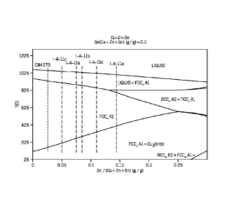
[0107] Figure 24 plots the position of the alloys in table 12 on a
copper/zinc/tin phase diagram.
The alloys proceed from the highest percentage of copper and zinc on the left
to the lowest
copper and zinc on the right. A phase distribution diagram of I-A-11a (Figures
25A and 25B), I-
A-11b (Figures 26A and 26B), I-A-11c (Figures 27A and 27B), I-A-11d (Figures
28A and 28B),
I-A-I le (Figures 29A and 29B), using Scheil cooling is shown. Figures 31,
32A, and 32B
correspond to Alloy I-A-12f. Figures 33, 34A, and 34E correspond to Alloy I-B-
12a. Figures 35,
36A, and 36B correspond to Alloy II-A-12a. The relative amounts of the melt
having FCC,
Liquid, BCCI, BCC2, Cu2S, and Cu3Sn in relation to temperature is shown in
Figures 26A, 26B,
27A, and 27B (magnified in 26B and 27B to show the distribution of the
secondary phases).
(01081 Figures 30A-30B illustrates a similar series of phase distributions as
Figures 25A-29, but
for an existing commercial alloy, C83470. Figure 30A is a phase distribution
diagram of
C83470 alloy using Schell cooling. Figure 30B is a magnified part of the phase
distribution
diagram showing the relative amounts of secondary phases.
101091 The phase distribution diagrams show the phase that can be expected and
the temperature
at which they start wearing. The relative amount of each phase can also be
estimated from
these diagrams. Table 12 is based on these diagrams which shows that for non-
equilibrium
cooling, it is the p (BCC1) phase (which is an intermeta/lic compound of Cu
and Zn) that
-21-
4822-8303-2592
4 .
itlitMED APT 34)
CA 02816320 2013-04-26
PCT/US2011 /058448 IPEA/KR (27-08-2012)
AUG. 27. 2012 3:24PM FOLEY & LARDNER NO. 7886
P. 38/78
ikttny Uocket No 055665-5144PC1
contributes to the strength of the alloys. However, strength increases at the
expense of ductility.
Sloan Green alloys show high strength and ductility. Their high ductility may
be due to the good
melt quality, low gas content and good homogeneity. The finer distribution of
sulfides also
contribute to high strength and high ductility in addition to contributing to
pressure tightness and
machinability.
Table 13: Liquidus Study
Alloy Type Liquidus Temperature Solidus Temperature Freezing
Range
C ( F) C ( F) C
Alloy I-A-11e 1043 (1910) 936(1717) 107(193)
Alloy I-A-11a 1041(1904) 942(1728) 991178)
, Alloy I-A-11b 1036(1897) 947 (1737) 89(160)
Alloy I-A-11d 1029 (1884) 948 (1738) 81 (14.6)
Alloy I-B-11a , 1035 (1895) 939 (1722)
96 (173)
C84400, Leaded Alloy, 1004(1840) 843 (1549) 161 (291)
Biwiditem, C83470 1013 (1855) 951(1744) 62(111)
BiwallteTM, C83470 1027, (1881) 982(1800)
45(81)
(Roported;
C90400 987 (1810) 852(1566) 135(244)
C90300, Leaded ABoy, 1000 (1832) 854 (1570) " 146(262)
Procedure:
[0110] Thermal investigation of the systems was performed using a DSC-2400
Setaram Setsys
Differential Scanning Calorimetry. Tempera= calibration of the DSC was done
using 7 pure
metals: In, Sn, Pb, Zn, Al, Ag, and Au spanning the temperatute range from 156
to 1065 C.
The samples were cut and mechanically polished to remove any possible
contaminated surface
layers. Afterwards, they were cleaned with ethanol and placed in a graphite
crucible with a lid
cover to limit possible evaporation and protect the apparatus. To avoid
oxidation, the analysis
chamber was evacuated to 1172 nabs/ and then flooded with argon. The DSC
measurements were
carried out under flowing argon atmosphere. Three replicas of each sample were
tested. The
weight of the sample was 62-78 mg.
10111] The sample was heated from room temperature to 1080 C. Then it was
cooled to 800 C
and kept at that temperature for 10 minutes, 600 5. This is termed "first
heating and cooling
-22-
4822-6303-2592
1VNED SHEEMOT,34)
CA 02816320 2013-04-26
PCT/US2011 /058448 IPEA/KR (27-08-2012)
CA 02816320 2013-04-26
AUG. 27. 2012 3:25PM FOLEY & LARDNER NO.
7886 P. 39/78
Attny Docket No 055665-5144PCT
cycle." In the second and third cycles the sample was heated to 1080 C and
then cooled to 800
C twice. Finally the sample was cooled down to room temperature. A constant
rate of 5 C /min
was used for all heating and cooling. A baseline experiment, with two empty
graphite crucibles
was run using the same experimental program. The baseline was subtracted for
all NILS. The
analysis for temperatures and enthalpies was carried on these baseline
adjusted thermogrEmrs.
[01121 The results from the second and third cycles were used to determine the
relevant thermal
parameters, namely the Tswit of melting , the To.t of solidification, and Tpuk
of melting and
solidification, as well as, the enthalpy, E, of melting and of solidification.
Usually, T., (heating)
and Tpeak (cooling) were taken as the Ts (solidus) and TL (liquidus).
[0113] The results of the liquidus study (Table 13) indicate that the
introduction of sulphides
appear to reduce the liquidus temperatures and the freezing ranges hi
comparison with the leaded
alloys. In the A-I group of alloys, as the Zn content increases, liquidus
temperature and the
freezing range decrease.
[01141 With respect to freezing ranges, BiwaliteTu(C83470), has a medium
freezing range. The
alloys of Table 13 have a broad freezing range. In contrast, with
BiwaliteTm(C83470), one can
expect a deep pipe in the riser which can extend to the casting to produce
shrinkage porosity.
With broad freezing range alloys, porosity can be distributed well in the
casting. In addition, it
can be minimized / eliminated by using proper risering design and/or by using
metal chills. In a
way, the alloys I-A, I-B, and II-A of Table 13 can be less susceptible to
shrinkage porosity. This
would lead to better strength and elongation values as observed.
Sulfide Particle Size
Table 14 Alloys for Particle Size Study
Biwalitem
Element Alloy I-A-14a Alloy I-A-14b Alloy II-A-14a C90300
C83470
Cu 88.26 90.46 ¨ 87.46 91.82 87.58
, Ag <0.01 <0.01 0.03 <0.01 0.02
Bi 0.01 0.01 0.07 0.01 0.02
Fe 0.16 0.05 0.16 r 0.26 0.09
-23-
4522-6303-2592
AILLE:FED SHEET( ART 24)]
PCT/US2011/058448 IPEA/KR (27-08-2012)
AUG. 27. 2012 3:25PM FOLEY & LAMER NO. 7886
P. 40/78
Attny Uooket No 055665-5144PCT
Mn <0.01 0.01 0.01 <0.01 <0.01
Ni 0.88 , 1.13 0.89 0.69 0.07
P 0.012 0.006 0.015 0.012 0.023
Pb 0.02 0.12 0.01 0.02 0.11
0.11 0.13 0.19 .59 0.012 ,
Sb <0.01 <0.01 <0.01 <0.01 0.01
Sn 3.23 3.63 8.18 4.02 8.22
Zn 7.32 4.45 2.99 2.58 3.84
Table 15 Particle Sizes
Alloy Minimum (pm) Mailman* (pm) Average (pm) -
Alloy I-A-14a , 0.1 9
Alloy I-A-14b 0.1 7 2
AJloy II-A-14a 0.1 14 2
Bilwalitem C83470 0.1 14 3
C90300 0.2 5 2
Alloy I-B-10a 0.1 5 , 1
Alloy III-A 0,1 5 1
Alloy I-A-10a 0.2 18 5
Alloy 1.1-A-10a 0.1 53 6
(01151 A study was done of the sulfide particles sizes of the alloys in Table
14 as well as select
alloys in Table 10. Table 15 lists the minimum, maximum and average particle
sizes for the
alloys. In addition, particle sizes were reviewed for two commercial alloys,
C83470 and
C90300. The alloys of the present invention provide, on average, a smaller
particle size than
C83470 and a small minimum particle size than the commercial alloy C90300.
Figure 46A-46B
illustrate photomicrographs of the commercial C83470 compared with a Group I-B
alloy (I-B-
14a).
10116] The foregoing description of illustrative embodiments has been
presented for purposes of
illustration and of description. It is not intended to be exhaustive or
limiting with respect to the
precise form disclosed, and modifications and variations are possible in light
of the above
teachings or may be acquired from practice of the disclosed embodiments. It is
intended that the
scope of the invention be defined by the claims appended hereto and their
equivalents.
4822-6303-2592
4ENOE
11t!f1 A!!2i
CA 02816320 2013-04-26