Note: Descriptions are shown in the official language in which they were submitted.
CA 02816365 2016-07-22
=
1
=
SUBMERSIBLE PROGRESSIVE CAVITY PUMP DRIVER
FIELD OF THE INVENTION
The present invention relates to a hydraulic submersible driver for a
rotary pump, for example a progressive cavity pump, in which the driver is
offset in
relation to the production tubing; and more particularly, the present
invention relates
to a method of operating the rotary pump using the driver so that the pump can
be
operated in reverse for flushing operations. The present invention further
relates to a
suitable connector for connection between the driver and the production tubing
so that
control lines of the driver can be located alongside and externally of the
production
tubing.
BACKGROUND
Currently, and in the past, progressive cavity pumps have been ran in
two pieces. First, the stator portion is ran in on standard jointed tubing.
Then, the rotor
portion is ran in on either jointed rods, or co-rod and stabbed into the
stator. The rods
are then connected to a rotary head at surface which turns the entire rod
string and
subsequently the rotor, which is inside the stator, and thus creating the
pumping
action. This type of system has a large number of disadvantages. The entire
process
requires multiple pieces of equipment, service rig, rod rig, co-rod rig,
accelerators,
tubing x-ray inspectors, etc. which leads to high service times and large man
power
exposure. Due to the nature of the pumping system it also requires various
down hole
and surface tools, such as stuffing boxes, no turn tools, tubing rotators,
rotary heads,
tag bars, etc.
One of the main disadvantages of this system is the mechanical wear
that occurs on the rod and tubing string due to the rotation of the rods. This
usually
eventually wears holes in the jointed tubing, and weakens the rods. This leads
to
rod/tubing failures, which then require servicing. Additionally, because the
rods are
rotated from surface, when a pump seizes or fails, the rotary head at surface
builds up
and stores torque. This creates the necessity to run additional tools such as
an anti-
'
CA 02816365 2013-04-29
WO 2012/055036 PCT/CA2011/050554
2
rotational tool. This is ran, because when the torque is let off of the rod
string the
string tends to back turn violently (which besides being a safety concern) can
cause
the tubing to back off and come apart, thus falling down hole. This highlights
another
limitation of this system in that you cannot turn the rotor backwards (which
would be
advantageous) because the tubing may back off, or any of the rod connections
may
back off because when rotating backwards, the threads can loosen off.
The rod/tubing combination is also a limitation because the rods are ran
inside the production tubing which then takes up space and cause's additional
restriction of the production area. The rods also increase the overall surface
area,
which increases friction loss. Additionally the friction loss is difficult to
combat
because of the concentric nature of this design. Alternative materials
(plastics,
fiberglass, etc.) that would normally assist in friction reduction cannot be
used due to
the aggressive nature of the rotation of the steel rods.
It is also difficult to space out the rotor properly. Spacing out, is when
the rotor and rods are ran into the well and the rotor is stabbed into the
stator, it is
necessary to land it in an appropriate place so that as the rod string
stretches due to
string weight and other factors, the lobes line up with the cavities. To do
this a tag bar
is normally ran on the bottom of the stator. This allows the rig crew to lower
the rotor
until it tags the tag bar. Then measurements are used to pull up to a certain
spot and
hang the rod string. This action, while fairly reliable, is by no means
certain.
The current method of application of rods and tubing is all steel. This is
a major drawback, as these types of wells tend to have a variety of corrosive
fluids
and gases present. This very often leads to corrosion issues on the production
string
and rods, as well as scale build up in the production string and rods. It
would be very
advantageous to use plastic lined products as the production conduit for
corrosion/scaling protection, as well as friction reduction. Due to the rotary
action of
the rods, lined jointed tubing cannot be used as the rods would beat it up,
and destroy
it with their rotary motion and wear.
The conventional system of rod strings extending through the production
string allows for a multiple unit service called a flush. Often with heavy oil
wells, the
CA 02816365 2013-04-29
WO 2012/055036 PCT/CA2011/050554
3
pump sands off and this requires servicing. To do this, often instead of
pulling the
entire completion, a coiled tubing unit with small coil is brought to
location, where it
then runs in beside the rods and tubing, down to the top of the rotor where
the tubing
string is then circulated clean. The coil unit then pulls out of the well, and
a flush-by
unit is used to pull the entire rod string up which is connected at the bottom
to the
rotor. This action pulls the rotor out of the stator. The flush-by then begins
to inject
water or oil into the production string forcing the through the stator into
the well bore,
forcing the well onto a vacuum. Once a certain amount of fluid has been pushed
into
the formation, the rotor is lowered back into place, the rod string is re-
hung, and
standard pumping operations begin. This operation also requires multiple
service
units, and often, because of the unpredictability of the rods inside of the
production
tubing, the coil unit may not be able to get entirely down, or worse, could
become
stuck, or lodged around the rods. Basically, things start to get pretty
congested with
rods and coiled tubing inside of small diameter, normally 3.5" OD., production
tubing.
When a flush is preformed, the fluid that is pushed/flushed down into the
well bore mixes with any solids in the hole, and helps to suspend the solids
for a time
so that when you put the pump back on normal operations, the mix of fluids and
solids
can be pumped to surface as per normal. In order to perform the aforementioned
flush, currently it is necessary to remove the rotor from the stator so that
one can flush
down through the stator into the well bore with a fluid pump at surface. Once
this is
achieved, the rotor is then lowered back into the stator, and normal pumping
operations can resume.
This moving of the rotor up and down is usually accomplished with the
above mentioned flush-by unit, or a service rig, both of which normally have
the fluid
pump with them. It is time consuming, and typically does not occur until the
rotor has
already torqued up due to solids as the only way to diagnose this prior to
torquing up
is with logic programming. Unfortunately if the programming reads it is
torquing up, all
it can do is shut it down. The system then sits static until equipment can be
mobilized, (which can be days) and while the well sits idle, the solids that
are
suspended in the production column begin to settle back down on top of the
rotor,
CA 02816365 2013-04-29
WO 2012/055036 PCT/CA2011/050554
4
which typically means that when the equipment arrives, the flush-by cannot
pull the
rotor out of the stator to perform the flush. The well then also requires a
coiled tubing
unit to clean out on top of the rotor before the flush can begin. If the coil
unit is
unsuccessful, a complete service may be required with a service rig which
includes
pulling everything out of the hole, including the tubing.
In current configurations, the progressive cavity pump (PCP) is deployed
on standard tubing and rods (or co-rod). As mentioned above, the connections
that
are inherent with this type of system are prone to backing off if the
rods/pump are
turned backwards. Additionally, as the rods torque up, they store energy, so
that once
the system goes down on high torque, the rods have a lot of stored energy. To
release that energy, the rotary heads at surface are turned backwards, or the
hydraulic pressure is allowed to bleed of, which allows the torque in the rods
to
dissipate by back spinning, sometimes very violently. When this occurs, there
is a risk
of the aforementioned back off of the tubing.
If that occurs, the tubing/rods can fall down the hole, causing additional
problems. Currently, to combat this backing off of the tubing, an external no-
turn tool
is commonly ran. It is connected towards the bottom of the tubing string, and
contacts
the casing of the well, and stops the tubing from turning backwards in the
event of the
rods spinning backward. It does not stop the rods from backing off as
mentioned
above, as the rods are inside the tubing, and the no-turn tool operates only
on the
jointed tubing. Because this tool is in contact with the casing, it is
difficult, or
impossible to get past it with anything to clean out the cellar/sump of the
well. This
means that over time, as the sump fills up with solids, the only way to clean
it out, is to
pull everything out of the hole, and perform a comprehensive cleanout. Flushes
only
flush to the intake of the pump, and do not clean the sump/cellar so periodic
cleanouts
are still necessary.
SUMMARY OF THE INVENTION
According to one aspect of the invention there is provided a submersible
pump driver assembly for use with a rotary pump having a stator and a rotor
rotatable
therein and which is in communication with production tubing extending in a
CA 02816365 2013-04-29
WO 2012/055036 PCT/CA2011/050554
longitudinal direction in a well casing, the pump driver comprising:
a drive motor comprising a rotary output rotatable about an output axis
extending generally in the longitudinal direction and an inlet port arranged
to receive a
drive input;
a production housing including:
a production passage extending between a production outlet
arranged for connection in series with the production tubing thereabove and a
production inlet arranged for connection in series with the stator of the
rotary pump
therebelow; and
a motor connection through which the rotary output of the drive
motor is arranged to communicate;
at least one control line arranged to extend alongside the production
tubing and to communicate the drive input from a wellhead of the well casing
to the
inlet port of the drive motor so as to drive rotation of the rotary output
relative to the
housing about the output axis;
the drive motor being supported relative to the motor connection of the
production housing such that the output axis of the drive motor is arranged to
be
offset in a radial direction in relation to at least a portion of the
production passage of
the production housing; and
a drive link arranged to extend through the production inlet of the
housing for connection in series between the rotary output of the drive motor
and the
rotor of the rotary pump so as to transfer rotation of the rotary output of
the drive
motor to rotation of the rotor in the stator of the rotary pump.
The driver and external control lines of the present invention eliminate
many limitations associated with the use of rod stings to drive a pump. The
entire
system is ran concurrently with one coiled tubing unit.
The driver system relieves issues associated with rod and tubing wear,
as it does not have rods, therefore no rod wear. It also does not store torque
like a
conventional system, as there are no rods to twist up and store energy. The
motor is
CA 02816365 2013-04-29
WO 2012/055036 PCT/CA2011/050554
6
solidly connected to the pump which allows the pump to be turned backwards,
which
is advantageous for self flushing, and assuring de-torque.
The driver also alleviates issues with the rods occupying space in the
production tubing, as it has no rods. Accordingly we are able to run
alternative
materials for our production tubing, which combats corrosion and can vastly
extend
the operational life of the entire string, and allows use of friction reduced
products,
which allows reduction of the overall size of the production tube, thus
reducing cost
and allowing for a greater range of activities in the size limited well bores.
The driver also alleviates issues with spacing out the rotor as the rotor is
ran in place inside the stator already at the appropriate setting before
placement
downhole. As there are no rods again, there is no fear of the rotor shifting
it's
placement due to stretch, or other forces. The driver does not require a tag
bar tool.
The driver allows for the same type of flush servicing as the prior art, but
in a much easier and more reliable fashion. First of all, only the coiled
tubing unit
(CTU) is required, not a flush-by as well. The CTU runs inside of the
production tube
very easily as there are no rods, past the motor which is off center to allow
this and
down to the top of the rotor. The production tube is then circulated over and
cleaned
out. In order to flush the well, the motor is run in reverse, turning the pump
backwards
which is possible because we have no rods or tubing to worry about turning
off. Once
the well is flushed, the system is put on normal pumping operations.
With the driver, it is also possible to run composite/plastic production
conduits because there are no damaging rods. Normally, the composite/plastic
products also could not be ran because of tensile strength limitations, but by
also
incorporating steel control lines as hydraulic circuits, the steel hydraulic
conduits also
support the entire weight including the composite product.
As described herein, the hydraulic submersible progressive cavity pump
(I-ISPCP) driver is designed to combat many disadvantages of the prior art. It
combines all of the service equipment (rigs, co-rod, flush-by etc.) into one
unit, which
is a coiled tubing unit, with which a FlatpakTM in general is designed to be
deployed
and serviced with. FlatpakTM relates to a production tubing as described in
PCT
CA 02816365 2013-04-29
WO 2012/055036 PCT/CA2011/050554
7
publication W02009/049420 by Collin Morris. As it is a continuous system that
is
deployed/retracted in one run, it does not have the need for other services.
As it is all
deployed at the same time, there is no need for a rod string, which removes
many of
the aforementioned inherit problems with the rods such as: no tag bar
necessary, the
rotor is ran in place resulting in factory spec fit at all times; torque up is
not an issue,
so no anti-rotation tools necessary; the pump can be rotated backwards, which
is very
advantageous; no-turn tools are unnecessary; rod radigan is unnecessary;
stuffing
boxes are unnecessary; horizontal deployment is no longer a rod wear problem
as
there are no rods; no rods; no jointed tubing; no service rig; no flush-by
units; no co-
rod; and no accelerator units.
The drive motor is preferably connected to the production housing such
that the output axis of the drive motor is arranged to be offset in the radial
direction in
relation to the production outlet of the production passage of the production
housing.
Preferably he drive motor is connected externally of the production
passage of the housing such that the production passage is arranged to
communicate
alongside the drive motor.
In one preferred embodiment, the drive motor is connected to the motor
connection of the production housing such that the output axis of the drive
motor is
substantially coaxial with the stator of the rotary pump.
The drive motor preferably comprises a hydraulic motor and said at least
one control line is preferably arranged to convey the drive input in the form
of
hydraulic fluid between the wellhead and the drive motor.
The control lines preferably include a hydraulic supply line in
communication with the inlet port of the drive motor and a hydraulic return
line in
communication with a return port of the drive motor. The control lines may
also
include a third injector line arranged for communicating fluids from the
wellhead
independently of the hydraulic supply line and the hydraulic return line.
Preferably there is provided a connector arranged for connection
between the production housing and the production tubing and said at least one
control line. Preferably the connector comprises an integral body having a
production
CA 02816365 2013-04-29
WO 2012/055036 PCT/CA2011/050554
8
port arranged for communicating between the production tubing and the
production
passage of the production housing and an auxiliary port associated with said
at least
one control line and arranged for communicating between the control line and
the
drive motor.
When used with existing jointed production tubing, the production port
preferably comprises a threaded connector for threaded connection to jointed
production tubing.
The auxiliary ports are preferably arranged for connection to the
respective control lines independently of the connection to the production
tubing. In
some instances the auxiliary ports comprise a protrusion formed on the
integral body
of the connector which is arranged for compression fit into the respective
hydraulic
control line. Alternatively, the auxiliary ports may be coupled to the
integral body of
the connector by a threaded connection, a welded connection, silver soldering,
or a
dimpled connection for example.
In some instance, the control lines and the production tubing each
comprise continuous tubing members and all of the continuous tubing members
are
commonly encased in a seamless and integrally formed casing surrounding the
continuous tubing members. The continuous tubing members are preferably
connected to the respective tubing members by substantially identical
connecting
means. The connecting means may comprise a compression fit, a threaded
connection, a welded connection, silver soldering, or a dimpled connection for
example.
Preferably the rotary pump comprises a progressive cavity pump in
which the rotor is eccentrically rotatable within the stator and the drive
link comprises
a rigid member connected between the rotary output of the drive motor and the
rotor
of the progressive cavity pump having a length arranged to transfer rotation
of the
rotary output of the drive motor to eccentric rotation of the rotor in the
stator of the
progressive cavity pump using fixed connections between the rigid member of
the
drive link and each of the rotary output and the rotor.
According to a second aspect of the present invention there is provided
CA 02816365 2013-04-29
WO 2012/055036 PCT/CA2011/050554
9
a method of operating a rotary pump having a stator and a rotor rotatable
therein
which is in communication with production tubing extending in a longitudinal
direction
in a well casing, the method comprising:
providing a pump driver assembly comprising:
a drive motor comprising a rotary output and an inlet port
arranged to receive a drive input; and
a production housing including a production passage extending
between a production outlet and a production inlet, and a motor connection;
connecting the production housing of the pump driver assembly in series
between the production tubing in communication with the production outlet and
the
stator of the rotary pump in communication with the production inlet;
connecting the drive motor of the pump driver assembly with the motor
connection of the production housing such that the output axis of the drive
motor is
arranged to be offset in a radial direction in relation to at least a portion
of the
production passage of the production housing;
connecting a drive link through the production passage between the
motor connection and the production inlet of the production housing so as to
be
connected in series between the rotary output of the drive motor and the rotor
of the
rotary pump so as to transfer rotation of the rotary output of the drive motor
to a
rotation of the rotor in the stator of the rotary pump;
providing at least one control line extending externally alongside the
production tubing; and
driving rotation of the rotary output relative to the housing about an
output axis extending in the longitudinal direction by communicating the drive
input
from a wellhead of the well casing to the inlet port of the drive motor
through said at
least one control line.
The method may include flushing the well casing by injecting coiled
tubing through the production tubing, injecting fluid into the production
tubing adjacent
the rotary pump through the coiled tubing, and driving rotation of the rotor
of the rotary
pump in a reverse direction to pump the injected fluid downwardly through the
stator
CA 02816365 2013-04-29
WO 2012/055036 PCT/CA2011/050554
of the rotary pump into the well casing.
When the drive motor comprises a hydraulic motor and said at least one
control line comprises a hydraulic supply line in communication with the inlet
port of
the drive motor and a hydraulic return line in communication with a return
port of the
drive motor, the method preferably includes driving rotation of the rotor of
the rotary
pump in the reverse direction by reversing a flow of hydraulic fluid in the
hydraulic
supply and return lines.
When monitoring a torque value of the rotary pump, the method may
further include providing a controller arranged to automatically operate the
rotary
pump for a prescribed duration in a reverse direction to pump fluid downwardly
through the stator in response to the torque value exceeding a prescribed
torque limit.
The method may also include injecting fluid into a sump area below the
rotary pump by injecting coiled tubing into the well casing alongside the
production
tubing and operating the rotary pump while the fluid is injected into the sump
area.
Preferably the rotor is positioned in the stator of the rotary pump prior to
injecting the production tubing down into the well casing so that the control
lines are
injected alongside the production tubing as the production tubing is injected
into the
well.
According to another aspect of the present invention there is provided a
tubing connector for use with a production assembly in a well casing including
production tubing extending in a longitudinal direction in the well casing; a
rotary
pump having a stator and a rotor rotatable therein; a production housing
including a
production passage extending between a production outlet arranged for
connection in
series with the production tubing thereabove and a production inlet arranged
for
connection in series with the stator of the rotary pump therebelow; and a
hydraulic
pump drive motor connected to a motor connection of the production housing and
which has a rotary output connected through the production inlet of the
production
housing to the rotor of the rotary pump; the tubing connector comprising:
an integral body arranged for connection in series between the
production housing and the production tubing;
CA 02816365 2013-04-29
WO 2012/055036 PCT/CA2011/050554
11
a production port in the integral body arranged for communicating
between the production tubing and the production passage in the housing;
the production port comprising a threaded connector for threaded
connection to the production tubing; and
at least one auxiliary port in the integral body which is separate and
external from the production port and which is arranged for connection between
the
hydraulic pump drive motor and a respective pump drive control line extending
externally alongside the production tubing.
Some embodiments of the invention will now be described in
conjunction with the accompanying drawings in which:
BRIEF DESCRIPTION OF THE DRAWINGS
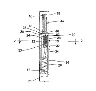
Figure 1 is a schematic elevational view of the hydraulic submersible
driver assembly for a progressive cavity pump in a production assembly in a
well
casing;
Figure 2 is a sectional view along the line 2-2 of Figure 1; and
Figure 3 is a front elevational view of a first embodiment of a connector
between the pump driver and pump control lines which extend externally
alongside
the production tubing.
Figure 4 is a front elevational view of a second embodiment of the
connector between the pump driver and the pump control lines in which the pump
control lines are encased in a common casing with the production tubing.
Figure 5 is an exploded elevational view of a further embodiment of the
hydraulic submersible driver assembly for a progressive cavity pump in a
production
assembly.
In the drawings like characters of reference indicate corresponding parts
in the different figures.
DETAILED DESCRIPTION
Referring to the accompanying figures, there is illustrated a hydraulic
submersible progressive cavity pump driver assembly generally indicated by
reference numeral 10. The driver assembly 10 is intended for use with a rotary
pump
CA 02816365 2013-04-29
WO 2012/055036 PCT/CA2011/050554
12
such as a progressive cavity pump 12 used on a production tubing string in a
production assembly of a hydro-carbon producing well.
Although various embodiments of the driver assembly 10 are described
herein, the common elements of the various embodiments will be described
first.
The progressive cavity pump 12 includes a stator 14 comprising a
tubular housing connected in series with production tubing 16 at the bottom
end of the
tubing string such that the housing extends in the longitudinal direction of
the
surrounding well casing 18. The pump further comprises a rotor 20 supported
within
the stator 14 for relative rotation such that lobes on the rotor interact with
lobes on the
stator to produce the progressive cavity pumping action. Due to the
interaction of the
lobes, the rotor is rotated eccentrically in relation to the stator. A forward
rotation of
the rotor corresponds to upward pumping of fluid from the surrounding well
casing
through the pump intake 21 at the bottom of the stator and subsequently
upwardly
through the production tubing 16 to the well head at the surface.
The driver assembly 10 includes a production housing 22 which is
connected in series between the stator 14 of the progressive cavity pump
therebelow
and the production tubing 16 extending thereabove. The housing includes a
production passage 24 communicating through the housing between a production
outlet at the top end of the housing which is arranged for connection in
series with the
production tubing thereabove and a production inlet at the bottom end of the
housing
which is arranged for connection in series with the stator of the pump
therebelow.
The bottom opening of the production inlet fully spans and aligns with the top
opening
of the stator of the progressive cavity pump. Similarly, the top opening of
the
production outlet is sized to fit and align with the production tubing with
which it
communicates. In the illustrated embodiments the top opening of the production
outlet is offset laterally to one side in relation to the bottom opening of
the production
inlet therebelow.
The production housing 22 also includes a motor connection 23
arranged for connection to a drive motor 26 of the driver assembly 10. The
motor
connection 23 is a branched passage connected to the production passage so as
to
CA 02816365 2013-04-29
WO 2012/055036 PCT/CA2011/050554
13
be located in parallel with the production outlet adjacent the top end of the
production
housing. In this instance, the output of the drive motor connected to the
motor
connection 23 and the production tubing connected to the production outlet of
the
production passage can both communicate commonly through the production inlet
at
the bottom end of the production housing while the drive motor 26 and the
production
fluids directed to the production tubing remain separated and laterally offset
from one
another.
The drive motor 26 comprises a hydraulic motor in the illustrated
embodiment. The motor includes an inlet port 28 for receiving a drive input in
the form
of hydraulic fluid from a suitable supply of fluid. Also located at the top
end adjacent
the inlet port is a return port 30 for returning the hydraulic fluid back to
the supply.
The hydraulic motor includes an impeller therein which is driven to rotate by
the flow
of hydraulic fluid which in turn drives a rotary output of the motor at the
bottom end
thereof. The rotary output is driven to rotate about a respective vertical
output axis
oriented parallel to the longitudinal direction of the production tubing and
well casing.
The drive motor 26 is supported relative to the production housing 22
such that the output axis of the motor is offset in a radial direction from a
central
longitudinal axis of the production outlet of the production housing to which
the
production tubing is connected in series. More particularly, the output axis
is offset
from an upper portion of the production passage 24 extending through the
production
housing along one side of the motor.
The drive motor 26 is mounted within a respective motor chamber
connected to the production housing which is external and offset in relation
to the
production passage so that the motor chamber and the production passage are
separated from one another. The bottom end of the motor chamber is sealed by a
suitable bearing box 32 and stuffing box seals so that the rotary output of
the drive
motor can be connected to the rotor of the progressive cavity pump therebelow
while
isolating the drive motor in the motor chamber from the production fluids
exiting the
progressive cavity pump therebelow and passing through the production housing.
The output of the gearbox 32 is coupled by a suitable drive link 34 to the
CA 02816365 2013-04-29
WO 2012/055036 PCT/CA2011/050554
14
top end of the rotor of the pump. The drive link in the illustrated embodiment
is a rigid
member connected through the production inlet of the lower portion of the
production
passage of the production housing 22 so as to be connected in series between
the
output of the drive motor at the motor connection 23 of the production housing
22 and
the rotor of the pump therebelow. The connection of the drive link to each of
the
rotary output of the motor and the rotor of the pump is a rigid connection
without any
pivotal or universal type connection being required due to the length of the
drive link
which may be in the order of 15 feet for example. The drive link thus has a
sufficient
length to transfer the rotation of the rotary output at the output axis to the
eccentric
rotation of the pump rotor therebelow while accommodating the slight angular
offset
between the drive motor output and the progressive cavity pump rotor to
eliminate the
eccentric motion without pivoting joints.
Below the drive motor, the production passage extending through the
housing of the driver is open to the area of the motor connection 22 of the
production
housing below the gearbox which surrounding the drive link. The drive link
thus
extends through a lower portion of the production passage while an upper
portion of
the production passage passes alongside the motor connection 22 to the drive
motor,
while being offset in a radial direction in relation thereto.
The top end of the driver housing 22 makes use of a suitable connector
36 which is arranged for connection to the production tubing 16 as well as
being
arranged for connecting the inlet and return ports of the motor to respective
control
lines 38. Although various embodiments of the connector 36 and control lines
38 can
be used, the common features of the various embodiments will first be
described
herein.
The connector 36 comprises an integral body having a production port
40 extending therethrough which communicates between the production tubing
thereabove and the production passage of the housing 22 therebelow. The
connector
also comprises an auxiliary port 42 associated with each control line 38 which
is
separate, external and laterally offset from the production port 40 for
independent
communication between a respective port of the drive motor 26 and a respective
CA 02816365 2013-04-29
WO 2012/055036
PCT/CA2011/050554
control line 38.
The control lines 38 are external, separate and offset in a radial direction
from the production tubing so as to extend alongside the production tubing
through
the well casing between the driver 10 and the well head thereabove. The
control line
serves to communicate the drive input from the wellhead to the drive motor. In
the
illustrated embodiment, the drive input comprises hydraulic fluid under
pressure which
is pumped downwardly from the wellhead through a respective control line to
the inlet
port of the drive motor and which is then subsequently returned through the
return
port and through a respective separate control line 38 back to the wellhead.
In alternative embodiments a single control line conducting electrical
conduits thereth rough for driving an electric drive motor can be used.
Turning now more particularly to the embodiment of Figure 3, a
connector 36 is shown for use with conventional jointed production tubing 16
in which
sections of tubing are joined with threaded connections. In this instance the
production port comprises a threaded projection formed integrally on the
integral body
of the connector onto which a lowermost section of the jointed production
tubing is
threadably connected.
The two control lines 38 shown in this instance comprise hydraulic
conduits for respectively supplying and returning hydraulic fluids to the
supply port
and return port of the drive motor. The two control lines comprise suitable
conduits for
containing high pressure hydraulic fluid such as steel conduits which are
encased in a
common casing 44 which surrounds both control lines and forms a continuous
member which is spoolable on a coiled tubing unit at the wellhead.
The two auxiliary ports 42 in the integral body on the connector in the
illustrated embodiment comprise projections 46 which can be compression fit
into the
respective conduits of the two control lines so as to be frictionally retained
therein by a
suitable clamping or dimpling of the conduits about the compression fit
projections 46
for interlocking connection therebetween in a mounted position. The connection
of
the auxiliary ports is thus independent of the connection to the production
tubing. In
further embodiments, the connection of the auxiliary ports may be accomplished
by a
CA 02816365 2016-08-24
16
compression fit, a threaded connection, a welded connection, silver soldering,
a
dimpled connection, or combinations thereof.
The two control lines in the common casing 44 can then be strapped to
the production tubing to extend alongside the production tubing along the full
length of
the production assembly in the well casing; however strapping may not be
necessary
in some instance.
Turning now to the embodiment of Figure 4, the two control lines 42 in
this instance similarly comprise hydraulic supply and return conduits
preferably
formed of steel which are connected to compression fit projections 46 on the
integral
body in the manner described above. The embodiment of Figure 4 differs from
the
previous embodiment in that the production tubing in this instance comprises a
continuous spoolable tubing member of composite material which is encased in
the
common casing 44 together with the two control lines which are also
continuous,
spoolable tubing members. The production tubing and two control lines together
with
the surrounding elastomeric casing are described in further detail in PCT
publication
W02009/049420.
The production port in this instance may also comprise a compression fit
projection 48 similar to the projections 46 so as to be inserted into the
respective
conduit forming the production tubing with the conduit being clamped or
deformed for
interlocking gripping connection therebetween in the mounted position. In
further
embodiments, the connection of the production port may also be accomplished by
a
compression fit, a threaded connection, a welded connection, silver soldering,
a
dimpled connection, or combinations thereof. Typically, the production port
and the
auxiliary ports are connected by identical connections to the respective
continuous
tubing members of the common casing 44.
The integral body of the connector in this instance serves to redirect the
production tubing centrally mounted between the two control lines to the
respective
production passage extending through the production housing of the driver
assembly
while the two control lines are redirected for communication with the offset
drive motor
connected to the offset motor connection of the production housing of the
driver 10.
CA 02816365 2013-04-29
WO 2012/055036 PCT/CA2011/050554
17
Turning now more particularly to the first embodiment of the production
housing 22 of Figures 1 and 2, the motor connection 23 in this instance
comprises an
integral connection between the production housing and the motor chamber
locating
the drive motor 26, and bearing box 32 therein. The production passage of the
production housing is supported to extend alongside the drive motor such that
the
production outlet at the top end of the housing and the input to the drive
motor are
arranged for direct connection to the connector 36 which connects to the
production
tubing and the control lines thereabove. The drive motor is supported in this
instance
by the motor connection of the production housing such that the output axis of
the
motor is offset in a radial direction from the stator of the progressive
cavity pump
therebelow and the production tubing connected to the production outlet of the
production housing thereabove.
Turning now more particularly to the second embodiment of the
production housing 22, as shown in Figure 5, the drive motor in this instance
is
supported externally and separately above the production housing 22. The
production housing in the second embodiment is substantially Y-shaped such
that the
branched passage of the motor connection 23 is substantially coaxial with the
production inlet at the bottom end of the production housing while the
production
outlet at the top end of the production housing is inclined and offset
laterally to one
side of the motor connection and production inlet. The stuffing box of seals
and the
bearing box 32 connect the drive motor 26 to the motor connection 23 such that
the
output axis of the rotary output of the drive motor is coaxial with the
production inlet
and pump stator connected therebelow.
The top end of the drive link is thus connected to the rotary output so
that the top end of the drive link is also coaxial with the pump stator
therebelow. An
additional drive housing 102 is connected coaxially and in series between the
production inlet at the bottom of the production housing and the pump stator
to
accommodate the length of the drive link which may be in the order of 15 feet
in
length in the longitudinal direction ,as described above. Fixed couplings at
the top and
bottom ends of the drive link ensure fixed connection to the output of the
motor and
=
CA 02816365 2013-04-29
WO 2012/055036 PCT/CA2011/050554
18
the top of the pump rotor respectively with the length of the drive link being
sufficient
to transfer the concentric rotation of the motor to eccentric rotation of the
pump rotor
without pivots being required also as described above.
In the second embodiment, the production outlet of the production
housing 22 communicates in series with an auxiliary production tube 100 which
extends alongside the drive motor between the production housing and the
connector
36. A top end of the auxiliary production tube 100 may be offset from the
bottom end
such that the top end can optionally be located coaxially with the motor
output at a
location above the motor when the bottom end is coaxial with the production
outlet of
the production housing 22.
As shown in Figure 5, when the second embodiment of the production
housing 22 is used with the production tubing of Figure 4, the production port
in the
connector may be arranged to connect between the production tubing thereabove
and
the auxiliary production tube 100 therebelow such that the motor is suspended
in line
below the production tubing with an output of the motor and the pump stator
therebelow being substantially coaxial with a central longitudinal axis of the
production
tubing. To provide support between the drive motor 26 and the auxiliary
production
tube 100 a rigid support member may span the length of the auxiliary
production tube
so as to be rigidly fastened to both a housing of the drive motor 26 and the
production
tube 100 along the length thereof between the connector 36 and the production
housing 22 to which the support member can also be fastened.
In use, the progressive cavity pump is first assembled by positioning the
rotor in the stator before placement in the well casing. The drive motor is
connected
to the motor connection of the production housing and the bottom end of the
production housing 22 is connected to the top end of the progressive cavity
pump with
the drive link connected between the output of the drive motor and rotor in
the suitable
manner. The bottom of the production tubing and the bottom ends of the control
lines
are then connected to the top of the production housing and motor using the
connector 36. In both embodiments the control lines are supported externally
and
alongside the production tubing so that the production tubing and the control
lines are
CA 02816365 2013-04-29
WO 2012/055036 PCT/CA2011/050554
19
injected into the well casing together as the production assembly is lowered
into the
well casing to its production position.
When using jointed production tubing, the control lines can be strapped
alongside the production tubing as it is inserted into the well casing.
Alternatively
when the production tubing comprises continuous spoolable tubing, the
production
tubing and the control lines can be spooled together from a single coiled
tubing unit
and injector head.
Once mounted in the desired production configuration, drive input is
provided by supplying hydraulic fluid from the wellhead through the control
lines to
drive rotation of the hydraulic drive motor which in turn rotates the output
thereof for
rotating the rotor relative to the stator. The housing of the drive motor is
anchored
relative to the housing of the driver 10 which is in turn fixed relative to
the stator of the
pump and to the production tubing.
When it is desired to perform a flush, a second coiled tubing unit is
provided and injected through the production tubing as well as through the
production
passage in the housing of the driver 10 until the bottom end of the injected
tubing is
located adjacent the top end of the progressive cavity pump. By switching the
communication of supply and return control lines at the wellhead, hydraulic
fluid can
be directed through the control lines in the reverse direction for operating
the drive
motor in the reverse direction which in turn rotates the rotor relative to the
stator in the
reverse direction. The reverse direction of the progressive cavity pump
corresponds
to the injected fluids being pumped downwardly through the pump and into the
surrounding well casing. Fluid may be continuously injected through the
injected
tubing from the second coiled tubing unit while pumping in the reverse
direction for
flushing the well with the rotor remaining intact within the stator of the
progressive
cavity pump.
in some instances, it may be desirable to configure the production
assembly to perform an automatic flushing in response to determination that
the
progressive cavity pump is operating under excessive torque. This is
accomplished
by providing a controller which continuously monitors a torque value of the
CA 02816365 2013-04-29
WO 2012/055036 PCT/CA2011/050554
progressive cavity pump corresponding to the resistance to the driving
rotation for
operating the pump. The controller is arranged to determine when the torque
value of
the pump exceeds a prescribed torque limit and in response to this
determination
halts the forward operation of the pump, reverses the flow of hydraulic fluid
through
the control lines and then operates the pump in reverse for a prescribed
duration.
Injected fluids may be simultaneously injected in an automated manner by the
controller in response to determination of the torque value exceeding the
prescribed
torque limit. After the prescribed duration or after it has been determined
that the
pump has been sufficiently flushed, normal forward pumping operation of the
pump
resumes.
For flushing the sump area of the well casing below the progressive
cavity pump, injected tubing from a second coiled tubing unit can also be
injected into
the well casing alongside the production tubing instead of through the
projection
tubing until the bottom end of the injected tubing is located in proximity to
the sump
area of the well casing directly below the pump. A continuous injection of
fluid in this
instance while the pump operates in the forward direction causes the injected
fluid to
collect deposits in the sump area which are then pumped upwardly through the
progressive cavity pump and upwardly through the production tubing to the
surface
until the sump area has sufficiently been cleaned out.
As described herein, the driver is specifically designed to be ran into a
well bore on a FlatPakTM or other multi-tubular conveyance system where the
tubulars
are not concentric, but are arranged on the same horizontal plane, and are
deployed
at the same time, and where at least one conduit is an injector, and one
conduit is a
producer, or one may be electrical in order to run the driver electrically,
preferably two
conduits to form a continuous hydraulic circuit, and one production conduit
for
evacuating production fluids from the well bore. The driver is connected to
both the
conveyance medium, and the progressive cavity pump with the rotor in place,
and
then deployed simultaneously. Hydraulics (or current) are then supplied to the
driver,
and the driver in turn runs the progressive cavity pump. Specifically, the
driver turns
CA 02816365 2013-04-29
WO 2012/055036
PCT/CA2011/050554
21
the rotor, which is ran in place inside the stator so that production fluids
then move to
surface up the production conduit.
The "Driver" Motor is in place above the pump assembly, and is
arranged slightly off center to allow for standard servicing when access to
the top of
the Rotor is necessary. Other systems, because of their concentric nature are
"centered" within their respective tubular, and thus are difficult or
impossible to service
without a complete rig intervention, (pulling the entire system, fixing on
surface, and
redeploying, which with a concentric system adds significant time and
equipment).
The HSPCP Driver is a subsurface rotary motor tool, which is driven by
hydraulics, or electricity. It is designed to power all types of Rotary style
pumps
(centrifugal, Progressive Cavity, etc.) but specifically Progressive Cavity
style pumps
of all sizes.
The Driver allows for reverse action of the Progressive Cavity Pump.
This allows the pump to pump backwards into the well bore, thus forcing fluid
(and
solids) back into the well bore and the formation. This is called a "flush".
The driver
allows for the system to "self flush" which is desirable, but with existing
technology, it
is difficult or impossible. The Driver makes it easy and reliable.
This is especially advantageous in Heavy oil wells where "flushing" the
well (as this forward push of fluid is called) is desirable because sand can
build up in
the "sump" or "cellar" over time until it begins to restrict the in-flow of
production fluids
into the well bore from the formation, as well as restrict flow into the pump
itself.
By powering the Progressive Cavity Pump hydraulically down hole with
the driver, the service equipment for flushing normally associated with a rod
string can
be eliminated, and the pump can be made to "self flush" manually, or
automatically,
with programming logic. Because the driver is directly atop of the pump, and
the
system is deployed by FlatPak, there are no (or very few), threads that can be
"backed off'. In a normal completion with rods, tubing etc., each connection
has a
thread and therefore can back off if the torque is reversed, (which is why
they don't do
it). With the Driver, there are few or no connections, thus allowing the pump
to be
turned backwards without the fear of "backing off' a rod or Pipe connection.
When the
CA 02816365 2013-04-29
WO 2012/055036
PCT/CA2011/050554
22
PCP is turned backwards, the fluid from the tubing is pump back into the well
bore,
thus performing the afore mentioned flush without any intervention equipment
at all.
Additionally, By automating the system, the hydraulic system can easily be
made to
automatically switch flow direction and perform a "self flush" whenever the
pump
begins to "torque" up. The system would read the increased hydraulic pressure
at
surface, indicating the rotor was beginning to get "tight", and before it got
bad, the
system would reverse hydraulic flow, thus turning the driver in reverse, which
in turn
would turn the PCP in reverse and "auto flush" the well. Once the torque had
subsided, or a predetermined amount of fluid was flushed, the surface system
would
once again switch flow, and the driver/pump would resume normal pumping
operations. By using this method, significant savings in servicing equipment,
and
down time can be realized.
In addition to self flushing, the HSPCP Driver allows for enough annular
space, that a continuous fluid injection string can be installed beside the
FlatPak.
With the PCP Driver and the FlatPak, issues associated with pulling up
a rod string and backspinning rods are eliminated. As the "back off' issue no
longer
exists, the No-turn tool can be eliminated. This allows for periodic cleanouts
into the
cellar/sump PAST the down hole assembly. The Driver/pump can be left pumping,
at
the same time that coil tubing is ran into the well bore, past the driver,
past the pump,
and into the cellar/sump. Fluids can then be injected through that cleanout
string to
"stir up" the solids in the cellar/sump, and help lift them up to the pump
intake. The
pump can then pump the mixture to surface. This process eliminates down time,
as
the process can be done on the fly, and eliminates all of the additional
service
equipment associated with a complete work over.
In addition to cleanouts, permanent strings can be ran into the cellar and
landed. These strings can then be used to inject a steady stream of fluids
into the
cellar/sump to ensure that solids don't build up.
Normally a HSPCP could be deployed using a FlatPak that incorporates
both of the hydraulic conduits (hydraulic drive circuit) and the production
tube. While
this method is useful, there are many situations where jointed production
tubulars are
CA 02816365 2016-07-22
23
already available on site, and to save on cost it may be desirable to use the
existing
production tubular. When this is the case, it may be advantageous to use a
smaller
Flatpak that consists of only the hydraulic circuit (two tubular), or possibly
two
individual tubes (not in a FlatPak configuration) which powers the PCP Driver.
In this
case, a coiled .tubing unit, spooling unit, (or some method of supplying the
FlatPak/individual tubes) and a Service Rig, Drilling Rig, Flush-by ( or some
method of
deploying the Jointed tubing) would be needed.
The PCP and Driver would be attached to the bottom of the production
string (on the rig), and then the FlatPak (hydraulic conduit) or individual
tubes would
also be attached to the driver by way of a connector, which attaches beside
the
jointed production string to power the PCP Driver, (but outside the production
string
as to not inhibit internal flow). Then as the Jointed production string is
lowered into the
hole one at a time, the FlatPak/individual strings (hydraulic circuit) would
be "slaved",
or "piggy backed" into the well off of the Coiled tubing unit, or spooling
unit. It may
also be desirable to "band" or "strap" the FlatPak/individual strings to the
side of the
Production string at intervals for vertical support. Once on depth, the
Jointed tubing
would be landed, and the FlatPak terminated.
When retrieving this system, the process would simply be reversed. The
jointed tubing would be pulled, and as it was retrieved one at a time,
(bands/straps
would be cut as they surface if they are present) and the FlatPak/individual
strings
would slowly be spooled up onto the coil/spooling unit. Once at surface, the
Driver
and PCP would be removed from the well bore.
Since various modifications can be made in my invention as herein
above described, and many apparently widely different embodiments of same
made,
it is intended that all matter contained in the accompanying specification
shall be
interpreted as illustrative only and not in a limiting sense.