Note: Descriptions are shown in the official language in which they were submitted.
CA 02816511 2013-04-29
WO 2012/170203
PCT/US2012/039077
SYSTEM AND METHOD FOR DATA INVERSION WITH PHASE
EXTRAPOLATION
FIELD OF THE INVENTION
The present invention relates generally to methods and systems for inverting
seismic data to
compute physical properties of the earth's subsurface, and in particular
methods and systems
for performing phase-only full waveform inversion to compute velocity models
from seismic
data.
BACKGROUND OF THE INVENTION
Subsurface exploration, and in particular exploration for hydrocarbon
reservoirs, typically
uses methods such as migration of seismic data to produce interpretable images
of the earth's
subsurface. In areas where the subsurface is complex due to faulting, salt
bodies and the like,
traditional migration methods often fail to produce adequate images.
Additionally, traditional
migration methods require a reasonably accurate velocity model of the
subsurface; such
velocity models may also be determined from the seismic data but may be very
expensive in
both expertise and computational cost.
There are many conventional methods for computing velocity models from seismic
data,
including NMO velocity analysis, migration velocity analysis, tomography, and
full
waveform inversion.
Some methods, such as full waveform inversion, are very
computationally expensive and have only recently become practical as computing
power has
increased. Conventional full waveform inversion is done in the time domain or
in a
transform domain such as the temporal Fourier transform domain or the Laplace
transform
domain. These methods often fail due to the lack of low frequencies, typically
less than 3
Hertz, in seismic data. As one skilled in the art will appreciate, a velocity
model is a low
frequency model so it is difficult to invert for it from the seismic data that
lacks the low
frequency information.
Traditional methods of determining velocity models and using them for
migration to produce
images of the earth's subsurface are expensive and fraught with difficulties,
especially in
complex areas. As the search for hydrocarbons moves to these complex areas, it
is necessary
to find better ways to process the seismic data and improve velocity models.
1
CA 02816511 2013-04-29
WO 2012/170203
PCT/US2012/039077
SUMMARY OF THE INVENTION
According to one implementation of the present invention, a computer-
implemented method
for inverting data from an area of interest to determine physical properties
of the area of
interest is disclosed. The method includes transforming the data into a
Fourier frequency
domain to obtain frequency domain data wherein the frequency domain data
includes an
amplitude portion and a phase portion, performing phase unwrapping of the
phase portion of
the frequency domain data to generate an unwrapped phase portion of unwrapped
data,
extrapolating the unwrapped phase portion to create extrapolated unwrapped
data, and
inverting the extrapolated unwrapped data to determine the physical properties
of the area of
interest. The extrapolation may create phase values at frequencies lower than
conventionally
usable frequencies in the data.
In an embodiment, a system for inverting data from an area of interest to
determine physical
properties of the area of interest is disclosed. The system includes a data
source, an user
interface, and a processor configured to execute computer modules designed to
implement
the method.
In another embodiment, an article of manufacture is disclosed. The article of
manufacture
includes a computer readable medium having a computer readable code embodied
therein,
the computer readable program code adapted to implement the method.
The above summary section is provided to introduce a selection of concepts in
a simplified
form that are further described below in the detailed description section. The
summary is not
intended to identify key features or essential features of the claimed subject
matter, nor is it
intended to be used to limit the scope of the claimed subject matter.
Furthermore, the
claimed subject matter is not limited to implementations that solve any or all
disadvantages
noted in any part of this disclosure.
BRIEF DESCRIPTION OF THE DRAWINGS
These and other features of the present invention will become better
understood with regard
to the following description, pending claims and accompanying drawings where:
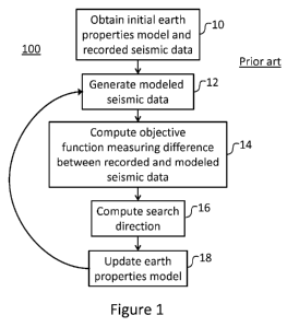
Figure 1 is a flowchart illustrating a method of full waveform inversion;
Figure 2 illustrates gradient bandwidths at various frequencies;
2
CA 02816511 2013-04-29
WO 2012/170203
PCT/US2012/039077
Figure 3 illustrates a conventional full waveform inversion process beginning
from a good
initial earth properties model;
Figure 4 illustrates a conventional full waveform inversion process beginning
from a poor
initial earth properties model;
Figure 5 is a flowchart illustrating a method in accordance with an embodiment
of the
invention;
Figure 6 illustrates a method of phase unwrapping with and without a
preconditioner at a very
low frequency;
Figure 7 illustrates a method of phase unwrapping with and without a
preconditioner at a
moderately low frequency;
Figure 8 illustrates a result of an embodiment of phase-only full waveform
inversion;
Figure 9 illustrates a result of another embodiment of phase-only full
waveform inversion
followed by conventional full waveform inversion;
Figure 10 is a flow chart illustrating another embodiment of the present
invention using phase
extrapolation;
Figure 11 illustrates a result of an embodiment using phase extrapolation; and
Figure 12 schematically illustrates a system for performing a method in
accordance with an
embodiment of the invention.
DETAILED DESCRIPTION OF THE INVENTION
The present invention may be described and implemented in the general context
of a system
and computer methods to be executed by a computer. Such computer-executable
instructions
may include programs, routines, objects, components, data structures, and
computer software
technologies that can be used to perform particular tasks and process abstract
data types.
Software implementations of the present invention may be coded in different
languages for
application in a variety of computing platforms and environments. It will be
appreciated that
the scope and underlying principles of the present invention are not limited
to any particular
computer software technology.
3
CA 02816511 2013-04-29
WO 2012/170203
PCT/US2012/039077
Moreover, those skilled in the art will appreciate that the present invention
may be practiced
using any one or combination of hardware and software configurations,
including but not
limited to a system having single and/or multiple computer processors, hand-
held devices,
programmable consumer electronics, mini-computers, mainframe computers, and
the like.
The invention may also be practiced in distributed computing environments
where tasks are
performed by servers or other processing devices that are linked through a one
or more data
communications network. In a distributed computing environment, program
modules may be
located in both local and remote computer storage media including memory
storage devices.
Also, an article of manufacture for use with a computer processor, such as a
CD, pre-recorded
disk or other equivalent devices, may include a computer program storage
medium and
program means recorded thereon for directing the computer processor to
facilitate the
implementation and practice of the present invention. Such devices and
articles of
manufacture also fall within the spirit and scope of the present invention.
Referring now to the drawings, embodiments of the present invention will be
described. The
invention can be implemented in numerous ways, including for example as a
system
(including a computer processing system), a method (including a computer
implemented
method), an apparatus, a computer readable medium, a computer program product,
a
graphical user interface, a web portal, or a data structure tangibly fixed in
a computer
readable memory. Several embodiments of the present invention are discussed
below. The
appended drawings illustrate only typical embodiments of the present invention
and therefore
are not to be considered limiting of its scope and breadth.
The present invention relates to computing physical properties of the earth's
subsurface and,
by way of example and not limitation, can compute a velocity model using phase-
only full
waveform inversion.
To begin the explanation of the present invention, first consider the basic
full waveform
inversion method 100 illustrated in the flowchart of Figure 1. At step 10, we
obtain an initial
model of earth properties, by way of example and not limitation, velocity.
Full waveform
inversion is a local optimization method and therefore depends strongly on
where the
optimization starts. For conventional full waveform inversion, there is a
strict condition on
the initial model in terms of what is required for the nonlinear evolution to
converge to a true
solution: the initial model must generate data that is within half a wave-
cycle of the observed
data at the lowest usable temporal frequency. It is important to note that
with the
4
CA 02816511 2013-04-29
WO 2012/170203
PCT/US2012/039077
conventional approach there is no easy way to determine if the initial model
meets this
condition, and the optimization can easily fail with a poor initial model.
In step 12, the initial model of earth properties is used by a seismic
modeling engine to
generate modeled seismic data. In general modeling can be performed in either
the time
domain or the frequency domain (temporal Fourier transform) with no penalty,
depending on
various factors like the size/extent of the modeling domain and the amount of
memory
available. Large 3D surveys typically require time-domain modeling because
frequency
domain modeling is extremely memory intensive for large numbers of model
parameters.
One significant advantage of frequency domain modeling is that one directly
has access to
both amplitude and phase, and this allows the use of "phase only" approaches
that can be
geared to be dominated by kinematics instead of amplitudes.
In step 14, we compute an objective function that will measure the misfit
between the
recorded seismic data and the modeled seismic data. The most widely used
objective
function for conventional full waveform inversion is simple least squares: the
sum of the
squares of the differences between the observed data and the modeled data for
all sources,
receivers and recorded time samples. However, this is not meant to be
limiting; other
objective functions can be used, including correlation, the Li norm, and
hybrid or long-tailed
norms. The objective function may be constructed in the time domain or in a
transform
domain such as the frequency domain.
In the time domain, the least squares objective function may take the form:
tv, v v
E = - Las a' L L.tIr
NI obs(t,r, s) ¨ igniod (t, r, s)] 2 Eqn. 1
2
where E is the objective function, s are the sources, r are the receivers, t
is time, vobs is the
recorded data, and igniod is the modeled data. This objective function suffers
from the critical
flaw that seismic data is bandlimited. Differencing of bandlimited signals
introduces the
possibility of "cycle skipping", where the wave shapes of the modeled and
observed data are
similar enough to cause a small difference, but are misaligned in an absolute
sense by (at
least) one wave cycle. This, together with the local nature of full waveform
inversion, leads
to the likely possibility that the nonlinear optimization will fail and
converge to a local
minima rather than the global solution.
One way to change the characteristics of the problem is to change the
objective function. If
we transform to the frequency domain we can consider objective functions at
one or more
5
CA 02816511 2013-04-29
WO 2012/170203
PCT/US2012/039077
frequency components individually (monochromatically). In the time domain, we
cannot
consider a single time sample because of dependence on earlier times. In the
frequency
domain, the response at different frequencies is uncoupled: the solution at
one frequency does
not depend on the solution at any other frequency. We can also, importantly,
treat amplitude
and phase differently. Taking the temporal Fourier transform of Eqn. 1, the
objective
function becomes:
1
MO = ¨Es Erkobs (a), r, s)eicpobs(w,r,$) _
Amod(C) , r, s)ei(pmod(w)12
Eqn. 2
2
where Aobs(co,r,$) is the amplitude of the observed data at receiver r, from
source s, at
temporal frequency co, coobs(co,r,$) is the phase of the observed data,
Aniod(o,r,$) is the
amplitude of the modeled data, and fliod(co,r,$) is the phase of the modeled
data.
In the frequency domain, we can consider the phase portion independently of
the amplitude
portion. For the phase-only case of full waveform inversion, by way of example
and not
limitation, the least squares objective function becomes:
1
E (a)) = ¨2E sErIT obs (a), r , S) ¨ Tmod(a), r , .5)12 = Eqn. 3
The modeled data in Eqns. 1-3 may be generated in the time or the frequency
domain. The
objective functions of Eqns. 1-3 measure the mismatch between the observed and
modeled
data and are decreased at each iteration. The inversion may be done as a phase-
only
inversion in either the time or frequency domain, as long as the mismatch can
be measured
directly or indirectly in terms of the phase of one or more frequency
components.
Once the objective function is computed in step 14 of Figure 1, a search
direction is
computed in step 16. In order to update the earth properties model and reduce
the misfit
between the observed and modeled data, the gradient of the objective function
is used to
generate a search direction for improving the model. The earth properties
model is then
iteratively perturbed along successive search directions until some
satisfaction criteria are
reached.
The calculation of the search direction becomes more clear if we treat the
modeled data as the
action of a nonlinear seismic modeling operator on the earth property model.
Using the
example of velocity (v) as the earth property, the operator being nonlinear
means that a linear
change in velocity does not necessarily result in a linear change in the
modeled data.
6
CA 02816511 2013-04-29
WO 2012/170203
PCT/US2012/039077
Using the symbol N to represent the nonlinear seismic modeling operator that
maps velocity
models into seismic data, and the action of this operator on the current
velocity model as
N(v), we can rewrite Eqn. 1:
E = -2Es Er Et[V,õ r, s) N(v)i2 Eqn. 4
so the derivative with respect to velocity becomes:
a a
E = ¨Es Er Eta Vobs(t, r, s) ¨ N(2)] -N (v)). Eqn. 5
av
Eqn. 5 shows that the derivatives used to update the earth property model
depend very
importantly on the modeling operator, the derivatives of the modeling operator
with respect
to velocity, and the current seismic data residual.
The nonlinear problem of full waveform inversion is solved by successive
linearization. For
the example of inverting for velocity, at iteration k, this is done by
linearizing around the
velocity vk, and seeking an update to the velocity 6v, such that the updated
model is: vk+i = vk
+ 6v. We need the linearization in order to compute the search direction.
Given the general
linear least squares system:
E= ¨ Axii2 Eqn. 6
The gradient or search direction can be written:
¨aE = Al[y ¨ Ax]. Eqn. 7
ax
Where A/ is the adjoint (conjugate transpose) of the linear operator A. For
our nonlinear
problem of full waveform inversion, we have the nonlinear operator N, and we
need the
adjoint of the linearized operator in order to compute a gradient. We use L
for the linearized
operator, and L/ for the adjoint of the linearized operator. The operator L
maps a vector of
velocity perturbations into a vector of wavefield perturbations, and the
adjoint operator L/
maps a vector of wavefield perturbations into a vector of velocity
perturbations (Eqn. 8).
L6vi =
L/602 = 6v2 Eqn. 8
Once the search direction is computed, we need to determine how large a step
to take in that
direction, which is how the earth properties model is updated in step 18 of
Figure 1. At least
7
CA 02816511 2013-04-29
WO 2012/170203 PCT/US2012/039077
two alternatives exist: a nonlinear line search, or solving the linear problem
using, by way of
example and not limitation, a Gauss-Newton methodology.
The majority of published conventional approaches employ steepest descent or
preconditioned steepest descent for nonlinear optimization. Once the search
direction is
estimated, these approaches forget about the current linear problem and use a
nonlinear line
search to estimate the best "step size" to take in the search direction. If we
use .3i, for the
search direction (usually the gradient of the objective function with respect
to the velocity
parameters), and a for the step size, we can express the nonlinear line search
as:
min t-21 Es Er Et [V,õ (t, r, s) ¨ N(v-Fcx 6v)]2}. Eqn. 9
One serious shortcoming of a nonlinear line search is taking such a large step
that the
modeled data becomes cycle skipped with respect to the observed data. This
could result in a
smaller residual and lead to convergence to a local minimum rather than the
true global
solution.
An alternative to using a nonlinear line search is to solve the linear problem
at each
successive linearization of the nonlinear evolution. Solving the linear
problem obviates the
need for a line search as the step size selection is implicit in the machinery
of linear
optimization, as in for example the conjugate gradient method. Solving the
linear problem
requires accurate machinery of the linearization: forward and adjoint
linearized operators that
pass the adjoint test. This often requires significant work, but can result in
significant
improvements in convergence. Using the linearized operators L and L/ described
above, we
can solve the linear system using, by way of example and not limitation,
conjugate gradient
on the normal equations. The linear system we want to solve is:
minilL8v ¨ 8012 Eqn. 10
where Sig is the current residual Sig = Vobs ¨ "0'
After the earth property model has been updated, the process loops back to
step 12 where the
updated model is used to generate modeled seismic data. Step 14 is performed
and, if the
difference between the modeled seismic data and the recorded seismic data is
large, steps 16
and 18 are also performed and looped back to step 12, until the difference at
step 14 is
sufficiently small or the number of loops or iterations reaches a predefined
number.
8
CA 02816511 2013-04-29
WO 2012/170203
PCT/US2012/039077
When attempting a conventional full waveform inversion, method 100 of Figure 1
has serious
limitations. First, full waveform inversion is a local optimization method,
which means it is
sensitive to where the nonlinear evolution starts. If the initial model is far
from the true
model, local approaches fail. This problem impacts all local methods,
including Newton and
quasi-Newton methods. For conventional full waveform inversion, it is
absolutely critical to
obtain a good starting model. In general, there are no obvious ways to
determine
quantitatively if a given starting model will converge to the true global
minimum.
Another serious limitation of conventional full waveform inversion is the
bandwidth
limitation. There is a direct relationship between the temporal bandwidth of
data used to
generate a gradient (search direction) and the spatial bandwidth of the
gradient obtained by
evaluation of Eqn. 5. Low temporal frequencies in the data produce long
spatial wavelengths
in the gradient. Consider Figure 2, which demonstrates this by plotting
gradients in spatial X
and Z coordinates computed at four frequencies. Note that at the lowest
frequency of 0.5 Hz
(panel 20) the calculated gradient is much more spatially smooth. At 1 Hz
(panel 21), 1.5 Hz
(panel 22), and 2 Hz (panel 23), the gradient becomes progressively less
smooth. The
bandwidth of seismic data is limited, and if correct long spatial wavelengths
of velocity do
not exist in the initial model, conventional full waveform cannot recover them
and in general
will fail and converge to a local minimum rather than the true global
solution. This directly
implies we should invert seismic data at the lowest usable frequency, in order
to employ
gradients that modify the long spatial wavelengths of velocity. However, the
lowest usable
frequency is seismic data is often not low enough to recover the longest
spatial wavelengths
and leads to a global minimum - this is a key limiting factor of the prior art
which the present
invention addresses.
Examples of the importance of the initial earth properties model for a
conventional full
waveform inversion can be seen in Figures 3 and 4. In Figure 3, the initial
velocity model
can be seen in panel 30. It is a smoothed version of the true velocity model
which is in panel
38. Panels 31-37 show the result of conventional full waveform inversion at 8
successive
frequencies: 1, 3, 5, 7, 9, 11, and 13 Hz. The final result in panel 37 is
quite accurate when
compared with the true velocity model in panel 38.
In Figure 4, the initial velocity model in panel 40 is constant and is set to
be water velocity.
This is far from the true velocity model in panel 48. Panels 41-47 show the
result of
conventional full waveform inversion at 8 successive frequencies: 1, 3, 5, 7,
9, 11, and 13 Hz.
9
CA 02816511 2013-04-29
WO 2012/170203
PCT/US2012/039077
While the uppermost part of the model is accurately recovered, the deeper
parts have
converged to a local minimum that is very far from the true solution. We can
conclude from
Figures 3 and 4 that conventional full waveform inversion must have a good
initial earth
properties model to converge to the correct solution.
Based on method 100 of Figure 1, the bandwidth of gradients of Figure 2, and
the initial
model requirements of the conventional full waveform inversion demonstrated in
Figures 3
and 4, the inventors have determined that a new method for full waveform
inversion is
needed. The present invention overcomes the bandwidth and initial model
limitations of the
conventional method.
An embodiment of the present invention is described by method 500 in Figure 5.
Many of
the steps of method 500 are similar to the steps of method 100 in Figure 1 but
method 500
does not suffer from the limitations of the conventional full waveform
inversion. To begin, at
step 50, the present invention sets an arbitrary initial earth model such as,
by way of example
and not limitation, setting the entire initial model to be water velocity of
1500 m/s. This
initial model is used to generate modeled seismic data at step 51. The forward
modeling of
the modeled seismic data may be done in the time domain or in the frequency
domain by any
of the many known forward modeling algorithms, such as finite difference
modeling. If the
forward modeling is done in the time domain, it may then be transformed to the
frequency
domain. In step 52, recorded seismic data is obtained and in step 53 it is
transformed into the
frequency domain. When both the modeled seismic data and the recorded seismic
data are in
the frequency domain, a residual phase may be computed at step 54, which is
the difference
between the phase portions of the modeled and recorded seismic data. At step
55, the
residual phase is phase unwrapped. It is also possible to unwrap the phase of
the modeled
seismic data and the recorded seismic data separately. The unwrapped phases
may then be
used to compute an unwrapped residual phase.
Phase unwrapping ensures that all appropriate multiples of 27r have been
included in the
phase portion of the data, meaning that the phase is continuous rather than
jumping by 27r.
There are methods for phase unwrapping but many fail for even moderate
frequencies such as
those greater than 2 Hz. Due to this, the inventors have developed a new
method for phase
unwrapping to prepare frequency domain data for inversion. The new method uses
a
particular type of left preconditioning that de-weights the influence of large
phase jumps.
Either the observed phase and modeled phase may be unwrapped individually or
their
CA 02816511 2013-04-29
WO 2012/170203
PCT/US2012/039077
difference, the residual phase, may be unwrapped. The latter is preferred
since the phase
differences between adjacent data points will be smaller.
The procedure we use for phase unwrapping is inspired by a fundamental theorem
of vector
calculus, also called the Helmholtz Decomposition. The Helmholtz Decomposition
can be
used to decompose a vector field into a curl-free component and a divergence-
free
component. We are interested in the curl-free component only, so we do not
require a precise
Helmholtz decomposition. The curl-free component is the gradient of a scalar
potential, and
is a conservative field. A conservative field is a vector field for which line
integrals between
arbitrary points are path independent. We identify unwrapped residual phase
with the scalar
potential whose gradient is the conservative field of a Helmholtz
decomposition.
We start by taking the gradient of the input wrapped phase, and adjusting by
adding or
subtracting 27r so that the result lies in the range [-R,+R]. This "adjusted
phase" is also known
as the "principal value" of the phase. Here "gradient" means the numerical
derivative along
the directions of source and receiver, respectively. We can write the
projection of the
adjusted gradient of phase onto a conservative field as follows:
V(Pres = 9 Eqn. 11
where ores -S i the unwrapped residual phase and g is the adjusted gradient of
the wrapped
T
phase, as explained above.
To calculate unwrapped phase, we discretize the gradient operator with respect
to source and
receiver coordinates and solve the overdetermined system shown in Eqn. 12 by
least squares.
In one embodiment, we find that a sparse QR factorization is a particularly
effective method
for solving this system of equations.
mini1V(Pres ¨ 9112 Eqn. 12
This approach of projection onto a conservative field for phase unwrapping has
difficulty at
moderate frequencies much greater than 1 Hz. For ns sources and nr receivers,
the system of
equation 12 will have ns*nr rows for the adjusted gradient with respect to
source coordinates,
and ns*nr rows for the adjusted gradient with respect to receiver coordinates.
It is therefore
twice overdetermined.
We found that failures of the system are related to large magnitudes of the
entries of the
adjusted gradient, and by weighting these large magnitude entries down, which
has the effect
11
CA 02816511 2013-04-29
WO 2012/170203
PCT/US2012/039077
of de-emphasizing their importance in the system of equations, we can
significantly improve
robustness. In an embodiment, the application of a diagonal left
preconditioner whose entries
are inversely proportional to the magnitude of the adjusted gradient greatly
improves the
performance of phase unwrapping at higher frequencies. Other types of
preconditioners may
also be used and fall within the scope of the present invention.
The new system is shown in equation 13, where the kth element of the left
preconditioner W
is inversely proportional to the magnitude of the components of the kth
element of the
adjusted gradient raised to the power a.
min iiW[V(Pres 91112
Wk,s = Igk,s1 c<
Wk,r = Igk,r1 Eqn. 13
In one embodiment, this user-defined positive power a may be set to 2.5. Using
this
embodiment, examples of phase unwrapping with and without the preconditioner
can be seen
for data at .5 Hz in Figure 6 and at 1.5 Hz in Figure 7. Both Figure 6 and
Figure 7 show the
wrapped phase in panel A, the unwrapped phase without use of a preconditioner
in panel B,
and the unwrapped phase with a left diagonal preconditioner in panel C. In the
low
frequency case in Figure 6, there is little difference in the results of
unwrapping with and
without the preconditioner. In Figure 7, however, the result without the
preconditioner has
erroneously changed the phase in the areas indicated by D and E, indicating
that as the
frequency gets higher, the preconditioning is necessary to obtain a good
result.
We note that this phase unwrapping approach does not require integration or
the specification
of boundary conditions in order to obtain unwrapped phase from the principal
value of the
gradient of wrapped phase.
In another embodiment, phase unwrapping may be used in a nonlinear line search
where the
search direction for velocity update has been pre-determined. There are at
least two
alternatives. In one alternative, a conventional objective function is used,
but data whose
residual phase magnitude exceeds 7E is excluded. This implies that the line
search is only
sensitive to data that is not cycle skipped. In another alternative, the
objective function for the
nonlinear line search is replaced with the least squares sum of the unwrapped
residual phase.
12
CA 02816511 2013-04-29
WO 2012/170203
PCT/US2012/039077
This means that the line search will correctly handle cycle skipped data. This
results in an
objective function very similar to that shown in equation 3, but with
unwrapped residual
phase (c) 1 as shown in equation 14. We further note that unwrapped residual
phase could be
,Tres,
used as an objective function for stochastic or Bayesian inversion in order to
correctly handle
cycle skipped data.
1 õ
E(co) = ¨2Ls Lr (Pres (a), r, s)2. Eqn. 14
Although the present method of phase unwrapping with a preconditioner has been
explained
in terms of preparing seismic data for inversion, this is not meant to be
limiting. One skilled
in the art will appreciate that unwrapped seismic data may be useful in other
processing flows
such as horizon flattening, homomorphic deconvolution, refraction statics, and
residual
alignment; and that other types of data, such as synthetic aperture radar,
could benefit from
this method of phase unwrapping with a preconditioner.
Referring again to Figure 5, once the unwrapped residual phase is available,
step 55 computes
an objective function measuring the misfit between the phases of the recorded
data and the
modeled seismic data. In an embodiment, this objective function might be Eqn.
3. In this
case, we perform phase-only full waveform inversion. To do so, we compute a
search
direction in step 56, update the earth property model in step 58, and iterate
over steps 51, 54,
55, 56, 57 and 58 until the objective function is sufficiently small or a
predetermine number
of iterations has been reach.
In an embodiment, as we iterate through the phase-only full waveform
inversion, we can
improve our ability to recover long spatial wavelengths, such as those for
velocity, by using a
continuation approach to regularize successive iterations and constrain them
to low
wavenumber updates. The continuation approach is application of homotopy to
smoothing
regularization for nonlinear optimization. Homotopy here means starting with
large
magnitude for smoothing regularization and gradually decreasing the magnitude
of the
smoothing regularization over the course of the nonlinear evolution.
Smoothing regularization can implemented by adding rows to the linear system
to penalize
roughness in the model that is optimized. There are numerous other ways to
implement
roughness penalties. In one embodiment, the continuation approach may use
analytic
derivatives of polynomials representing slowness. A change of basis to smooth
functions, for
example radial basis functions, also works. Other possibilities include but
are not limited to
13
CA 02816511 2013-04-29
WO 2012/170203
PCT/US2012/039077
the spatial Fourier basis with a right preconditioner that scales with
wavenumber, and 1st or
21d numerical derivatives, either centered or not. In yet another embodiment,
roughness
penalties may be applied by application of lst forward numerical differences
to pixelized
models. These examples are not meant to be limiting; one skilled in the art
will appreciate
that there are many more possible regularization operators that may be used in
the context of
the continuation approach which fall within the scope of the present
invention.
Expanding on the idea of smoothing regularization by the use of derivative
penalties using lst
order numerical differences, let us begin with a simple 3x3 pixelized velocity
model. In two-
dimensional space, the 9 velocities (vx,z) would appear as:
V1,1 V2,1 V3,1
V1,2 V2,2 V3,2
V1,3 V2,3 V3,3
Table 1: 3x3 velocity model
[0001] Writing this velocity model as a column vector, we get:
ivv),,)
121,3
122,1
122,2
I v2,3 I
',23,1)
123,2
v3,3
We can apply horizontal derivative penalties (a roughness penalty in the X
direction) by
penalizing the difference of adjacent velocities, e.g. (v1,1-v1,2). Note that
the formal forward
numerical derivative is written ¨a f (x) = f (x-FA)- f (x), but we can clear
the denominator. This
ax A
results in the matrix of horizontal derivative penalties shown:
14
CA 02816511 2013-04-29
WO 2012/170203
PCT/US2012/039077
(
ivv1:1) vt3 21 7 \
v,
0 0 +1 0 0 -1 0 0 0 ) , V3 \ 0/ 0
'2,2 =
0 0 0 +1 0 0 -1 0 0 0
122,3
0 0 0 0 +1 0 0 -1 0 0
,1
0 0 0 0 0 +1 0 0 -1
µ 123,2 1
and a similarly constructed matrix of vertical derivative penalties:
/121,1\
i v1,2
(+1 ¨1 0 0 0 0 0 0 0 ,1,3 0
v
0 +1-10 0 0 0 0 0 (0
V,
0 0 0 +1 -1 0 0 0 0
21 0
=
00 00 00 00 +0 1 . -0 1 . +0 1 01 00 Vv 22 : 23 00
V31
0 0 0 0 0 0 0 +1 -1 , 0
123,2 i
\123,31
Note there are fewer rows than columns because the derivatives only involve
horizontally or
vertically adjacent pixels.
These horizontal and vertical derivative matrices can also be written as:
)-x Dv = 0
AzDzv = 0 Eqn. 15
where v is the column vector of velocities, Dx is the matrix of horizontal
derivatives, D, is the
matrix of vertical derivatives, and kx and kz are Lagrange multipliers.
The continuation approach starts with the Lagrange multipliers kx and kz
large, and therefore
initial solutions in the first "continuation step" are very smooth. Clearly
this can aid in
recovering the long spatial wavelengths of velocity. As the nonlinear
evolution proceeds, we
take additional continuation steps and the magnitudes of kx and kz are
decreased. As the
magnitude of the penalties is decreased, successively shorter spatial
wavelengths are allowed
in the velocity model.
CA 02816511 2013-04-29
WO 2012/170203
PCT/US2012/039077
There are many possible options for setting the initial 2,x and 2,z values. If
chosen sufficiently
large, only very long spatial wavelengths are allowed in the model, and the
nonlinear
evolution effectively becomes independent of the initial model. If chosen too
small, the
problem will not be regularized enough and independence from the starting
model is lost.
One embodiment for the initial values of these parameters is to normalize them
by the
operator norm of the linearized operator at each successive linearization. If,
at the beginning
of the nonlinear problem in the first linearization, we have the linear system
Ax=y, we set 2,x
and 2,z to be scaled by the operator norm HAIL 11A 11 can be obtained, for
example, using the
power method.
The phase-only full waveform inversion performed in the present invention may
also include
more accurately solving the linear problems at each iteration. If, at each
successive
linearization, we solve the Gauss-Newton problem to obtain the model update,
rather than
employ the combination of steepest descent and a line search, we get an
improved result.
For the nonlinear problem of full waveform inversion, we linearize around the
velocity at
iteration k (vk), and seek to obtain an update to the velocity 6v such that
the updated model is:
vo+/) = vo + 6v. This is successive linearization. The application of
derivative penalties to
the linear problem implies that we want the update to the model to be smooth,
as shown here:
2L,D,6v = 0
il,D z6v = 0 Eqn. 16
A more desirable approach is to regularize the nonlinear problem. This implies
we want the
updated model to be smooth:
il,D,(vk + 6v) = 0
2.,D,(vk + 6v) = 0 Eqn. 17
This requires a non-zero right hand side, but the right hand side is easily
obtained by
application of the derivative operators Dx and Dx to the current velocity:
2L,D,6v = ¨ilx.D xv k
il,D z6v = ¨ilzDzvk Eqn.18
Figure 8 shows the result of an embodiment of the present invention, a phase-
only full
waveform inversion using phase unwrapping with a left preconditioner,
continuation
16
CA 02816511 2013-04-29
WO 2012/170203
PCT/US2012/039077
approach, and solving the successive linear problems. Panel 80 is the initial
model, which is
a constant 1500 m/s (water velocity). This is the same initial model that was
shown in Figure
4 panel 40. Panel 88 in Figure 8 shows the true velocity model. Panels 81-87
show
successive nonlinear iterations at 1 Hz, beginning from the initial model.
Panel 81 shows
that, after one iteration, accurate long spatial wavelengths are present in
the inverted model
and they are refined as the iterations progress through panels 82-87. Seven
nonlinear
iterations allow the recovery of the missing long spatial wavelengths of
velocity not possible
using the conventional approach, as seen in Figure 4.
In another embodiment of the present invention, the model generated by the
phase-only full
waveform inversion may be used as an initial model for conventional full
waveform
inversion. This is demonstrated in Figure 9, where the initial model for the
conventional full
waveform inversion in panel 90 is the model generated by 7 iterations of phase-
only full
waveform inversion in Figure 8, panel 87. Performing 5 iterations of
conventional full
waveform inversion (panels 91-95) at 2.5 Hz results in an inverted model
(panel 95) that is
very comparable to the true velocity model in panel 96.
Figure 10 illustrates yet another embodiment of the present invention. In this
embodiment,
the phase-only full waveform inversion flow is shown as method 1000. The steps
are the
same as those of method 500 in Figure 5 with the addition of step 1007, phase
extrapolation,
after the phase unwrapping step 1006. Steps 1001, 1002, 1003, 1004, 1005,
1006, 1008,
1009, and 1010 are performed in the same manner as steps 50, 51, 52, 53, 54,
55, 56, 57, and
58, respectively. Step 1007 is a phase extrapolation step which may be used to
extrapolate
the unwrapped phase to lower frequencies than exist in the recorded seismic
data. This very
low frequency phase information can then be used in steps 1008, 1009, and 1010
to aid the
recovery of the very long spatial wavelengths that make up the velocity model.
The present method of phase extrapolation uses the relationship between linear
phase shift
and traveltime:
(pfi = 27-c fit Eqn. 19
where (Pp is the phase at frequency fi and t is the traveltime. To extrapolate
the phase to
another frequency f2 and assuming that the traveltime does not change, we
solve for t and
substitute it:
17
CA 02816511 2013-04-29
WO 2012/170203
PCT/US2012/039077
t = (Ph Eqn. 20
2 irfi
f2
( f2 = 27-c f2t = (pfi ¨fi Eqn. 21
In this embodiment, the phase is extrapolated to lower frequencies than those
observed and
conventionally usable. Conventionally usable frequencies are typically greater
than 2 Hz.
This is done by linearization of the unwrapped phase as a function of
frequency and may be
applied to the observed phase, the modeled phase, or the residual phase. The
extrapolated
data is then inverted using some objective function defined to measure phase
mismatch. The
method is applicable for any case when the phase is linear in frequency.
Figure 11 illustrates the result of one embodiment of a phase extrapolation
method. Panel
110 is the initial model, in this case constant water velocity of 1500 m/s and
panel 121 is the
true velocity model. Panels 111-115 are phase extrapolation inversion from 2.5
Hz to 0.1,
0.2, 0.3, 0.4, and 0.5 Hz, respectively. Panels 116-120 are conventional
inversion at
frequencies 2.5, 4.5, 6.5, 8.5, and 10.5 Hz continuing from the phase
extrapolation result in
panel 115.
One skilled in the art will appreciate that there are many other possible uses
of phase
extrapolated data. By way of example and not limitation, synthetic aperture
radar (SAR) data
may be obtained, phase unwrapped using a preconditioner, and phase
extrapolated prior to
SAR imaging methods. Additionally, data that has been phase unwrapped using a
preconditioner and phase extrapolated may then be used to evaluate a cost
function. One
example is the use of unwrapped phase to compute an objective function for
stochastic or
Bayesian optimization, with the advantage that the cost function would
correctly handle
cycle-skipped data.
Although the embodiments above have been explained in terms of two dimensional
models,
the methods are easily extended into three dimensions and multi-parameter
earth models.
The methods for phase unwrapping, phase extrapolation, and phase-only full
waveform
inversion disclosed in the present invention may be extended into multiple
dimensions and
remain within the scope of the present invention.
A system 1200 for performing the method is schematically illustrated in Figure
12. The
system includes a data storage device or memory 130. The data storage device
130 contains
recorded data and may contain an initial model. The recorded data may be made
available to
18
CA 02816511 2013-04-29
WO 2012/170203
PCT/US2012/039077
a processor 131, such as a programmable general purpose computer. The
processor 131 is
configured to execute an initial model module 132 to create an initial model
if necessary or to
receive the initial model from the data storage 130. The processor 131 is also
configured to
execute the domain transform module 133 for transforming recorded and
optionally modeled
data into the frequency domain, the data modeling module 134 for forward
modeling data
based on the initial and updated models, the phase preparation module 135 for
phase
unwrapping with a preconditioner and optionally phase extrapolating the
recorded data, the
objective function module 136 for computing the objective function that
compares the
modeled data with the phase unwrapped recorded data, the search direction
module 137 for
determining the search direction, and the model update module 138 for updating
the model.
The processor 131 is also configured to execute modules 134, 135, 136, 137,
and 138
repeatedly until the result from the objective function module 136 meets user
requirements or
a maximum number of iterations is reached. The processor 131 may include
interface
components such as a user interface 139, which may include both a display and
user input
devices, and is used to implement the above-described transforms in accordance
with
embodiments of the invention. The user interface may be used both to display
data and
processed data products and to allow the user to select among options for
implementing
aspects of the method.
While in the foregoing specification this invention has been described in
relation to certain
preferred embodiments thereof, and many details have been set forth for
purpose of
illustration, it will be apparent to those skilled in the art that the
invention is susceptible to
alteration and that certain other details described herein can vary
considerably without
departing from the basic principles of the invention. In addition, it should
be appreciated that
structural features or method steps shown or described in any one embodiment
herein can be
used in other embodiments as well.
19